
Energy Aware Routing in IEEE 802.11s Wireless Mesh Networks
Maria Zogkou
1
, Aggeliki Sgora
2
and Dimitrios D. Vergados
1
1
Department of Informatics, University of Piraeus,80 Karaoli & Dimitriou St., GR 18534, Piraeus, Greece
2
VTT Technical Research Centre of Finland, FI 90571, Oulu, Finland
Keywords:
IEEE 802.11s WMNs, HWMP, Airtime Link Metric, Energy Aware Routing, QoS.
Abstract:
Wireless Mesh Networking is a continuous growing technology that can be used used for several application
scenarios, such as military tactical operations, etc. in next generation wireless networks. The IEEE 802.11s
Standard defines the procedures that wireless nodes follow in order to interconnect and create a Wireless Local
Area Network (WLAN) mesh network. It, also, defines the routing protocol and the metric that are used by
a IEEE 802.11s mesh network to route data. However, although the energy consumption of mesh nodes is a
crucial parameter for the network’s lifetime in specific purpose operations (e.g. military and health) the default
metric proposed by the standard doesn ’t take into account the energy of the nodes. In this paper, a new energy
- aware routing metric for the IEEE 802.11s mesh networks has been implemented. Simulation results showed
that the proposed metric prolongs the lifetime of a WMN in comparison with the the default metric used by
IEEE 802.11s Standard while causing a little higher total delay in the network.
1 INTRODUCTION
Wireless Mesh networking is a promising solution for
next generation wireless networks that envisages sup-
plementing wired infrastructure with a wireless back-
bone for providing Internet connectivity to mobile
nodes (MNs) or users in residential areas and offices,
and could be called the Web-in-the-sky (Nandiraju
et al., 2007). Wireless Mesh Networks (WMNs) at-
tract more and more the attention of the research com-
munity due to their low cost implementation and ro-
bustness. Mesh networking is considered the most ap-
propriate technology for Military/Government wire-
less networks (Shyy, 2006). However, in these net-
works several factors should be taken into acount,
such as mobility, QoS support, power management
etc.
IEEE developed an amendment of the IEEE
802.11 Standard, namely the IEEE 802.11s Standard
(802.11s 2011/D12.0, 2011), for mesh networking
in Wireless Local Area Networks (WLANs). The
aforementioned Standard defines the Hybrid Wireless
Mesh Protocol (HWMP) as the path selection proto-
col used by IEEE 802.11s WMNs. The default metric
of HWMP is the Airtime Link Metric (ALM) which
does not take into account the energy of the nodes in
the network and thus, the routing mechanism is not
energy - efficient.
In this paper, we deal with problems caused by
Figure 1: An IEEE 802.11s Architecture.
n
odes that suffer from energy exhaustion and we pro-
pose an energy aware routing metric that can ad-
dress connectivity problems in IEEE 802.11s net-
works. This energy aware metric is used by HWMP
routing protocol instead of the airtime link metric. In
particular, the proposed metric takes into account the
residual energy of nodes and selects the route that is
made up by nodes with the maximum residual energy
in the mesh network. Thus, nodes with low energy
levels do not participate in the routing procedure and
remain operational for longer periods of time. This
results in the prolonging of the network lifetime.
The rest of the paper is organized as follows: The
basic components of an IEEE 802.11s WMN archi-
215
Zogkou M., Sgora A. and Vergados D..
Energy Aware Routing in IEEE 802.11s Wireless Mesh Networks.
DOI: 10.5220/0004634302150220
In Proceedings of the 10th International Conference on Signal Processing and Multimedia Applications and 10th International Conference on Wireless
Information Networks and Systems (WINSYS-2013), pages 215-220
ISBN: 978-989-8565-74-7
Copyright
c
2013 SCITEPRESS (Science and Technology Publications, Lda.)

tecture are presented in Section 2, while Section 3 de-
scribes briefly the HWMP, defined in IEEE 802.11s
Standard. Section 4 overviews several existing rout-
ing metrics in WMNs, while in Section 5 the proposed
energy - aware routing metric is presented. Simula-
tion results are discussed in Section 6. Finally, Sec-
tion 7 concludes the paper.
2 THE IEEE 802.11s
ARCHITECTURE
The basic component of an IEEE 802.11s architec-
ture is the mesh station (STA), i.e an autonomous sta-
tion that implements the mesh functionalities, such
as formation of the mesh BSS, path selection, and
forwarding. The mesh facilities are available to the
mesh STAs that belong to a Mesh Basic Service Set
(MBSS).
Mesh STAs within the MBSS can communicate
with each other either directly, or through other mesh
STAs. Communication with nodes outside the MBSS
can be achieved through the Distribution System
(DS).
A mesh STA that can also provide access to one
or more DSs, via the wireless medium (WM) for the
MBSS is called mesh gate. Once an MBSS contains
a mesh gate that connects it to the IEEE 802.11 DS,
the MBSS can be integrated with other infrastructure
Basic Service Sets (BSSs) too, given that their Access
Points (APs) connect to the same DS.
When a MBSS accesses the IEEE 802.11 DS
through its mesh gate, the MBSS can be integrated
with a non-IEEE-802.11 LAN. Whereas the por-
tal integrates the IEEE 802.11 architecture with a
non-IEEE-802.11 LAN, the mesh gate integrates the
MBSS with the IEEE 802.11 DS.
Figure 1 depicts an IEEE 802.11s Architecture.
3 THE HYBRID WIRELESS
MESH PROTOCOL (HWMP)
The default routing protocol defined in IEEE 802.11s
Specification is the HWMP, which is operated on the
Data Link Layer and therefore it uses the MAC ad-
dresses for routing. Also, the specification defines the
ALM as the default metric used by the HWMP for
path selection. The ALM reflects the total channel re-
sources consumed by the transmission of a frame over
a particular link and is given by the following equa-
tion.
c
a
=
h
O+
B
t
r
i
1
1− e
f
(1)
where, O and B
t
are constants listed in Table I and the
input parameters r and e
f
are the data rate in Mbps
and the frame error rate for the test frame size B
t
re-
spectively.
Table 1: Airtime Cost Constants.
Parameter Recommended
Value
Description
O Varies de-
pending on
the PHY
Channel access over-
head, which includes
frame headers, train-
ing sequences, access
protocol frames, etc.
B
t
8192 Number of bits in test
frame
HWMP operates in two different routing modes:
the “on - demand” and the “tree-based proactive”
modes.
In the “on - demand” mode, whenevera mesh STA
needs to establish a routing path to a destination mesh
STA, it broadcasts a Path Request (PREQ) message to
all its neighbors having specified the sequence num-
ber, the address of the destination mesh STA, and the
ALM metric initialized to the initial value of the ac-
tive path selection metric. Upon receiving a PREQ,
if the node that received the PREQ is not the destina-
tion mesh STA acts as follows: First, it creates a path
to the source mesh STA if no path exists, or it up-
dates its current path in two cases: 1) if the sequence
number of the PREQ is greater than the last one; 2) if
the sequence number is the same with its current path
but propagates a better metric for the path. Then, it
calculates its routing metric and updates the PREQ
with the cumulative metric. The updated PREQ is
forwarded to all its neighbors. This procedure is re-
peated until the PREQ reaches its destination. When
the destination mesh STA receives the PREQ, it cre-
ates or updates its routing path to the source node and
it sends unicast Path Reply (PREP) message back to
the source mesh STA.
In the “tree-based proactive” mode, there are two
mechanisms, namely, the proactive PREQ and the
proactive RANN (Root ANNouncement). The proac-
tive PREQ mechanism creates paths from the mesh
STAs to the root, using only group-addressed com-
munication. The RANN mechanism creates paths be-
tween the root and each mesh STA using acknowl-
edged communication.
It should be noted that on-demand and proactive
modes can be used concurrently, because the proac-
tive modes are extensions of the on-demand mode.
WINSYS2013-InternationalConferenceonWirelessInformationNetworksandSystems
216

4 WMNS’ ROUTING METRICS
Although the ALM takes into account the transmis-
sion rate, as well as, the transmission error rate,
since it does not define any load mechanism it can
route traffic to congested areas (Islam et al., 2010).
Also, the fact that the ALM is unaware of intra-flow
interference has a significant effect on the network
performance in Multi-Channel Multi-Radio WMNs
(Bin Ngadi et al., 2012). Furthermore, issues such
as energy and security are not considered. However,
although extensive research carried out for the design
of new metrics very few works have focused on the
path selection mechanism for IEEE 802.11s WMNs.
One of the first metrics designed for WMNs is the
Expected Transmission Count (ETX) metric (Camp-
ista et al., 2008) that calculates the expected num-
ber of transmissions required to successfully send
a packet over the link, including retransmissions.
However, ETX does not take into account either the
packet size or the bandwidth of the links. There-
fore, it increases the control overhead, which results
in low network performance. In order to confront the
aboveshortcomings, the Expected Transmission Time
(ETT) (Draves et al., 2004) has been introduced that
considers also and the throughput into its calculation.
Koksal and Balakrishnan (2006) also proposed two
variations of the ETX metric that estimate the losses
by means of the bit error probability: the modified
Expected Number of Transmissions (mETX), and the
Effective Number of Transmissions (ENT).
Mhatre et al. (2007) proposed the Expected
Throughput (ETP) metric, which measures the ex-
pected throughput of the link. Also, Passos et al.
(2006) proposed the Minimum Loss (ML) metric that
calculates the delivery ratio and selects the route with
the lowest end - to - end loss probability by multiply-
ing the delivery ratios of the links across the path. Es-
pecially, for IEEE 802.11s WMNs Islam et al. (2010)
proposed the Expected Forwarding Time (EFT). EFT
calculates the end - to - end delay that a packet ex-
periences on its way to the destination and selects the
path that has the lowest end - to - end delay to route
packets.
Furthermore, for multi-channels WMNs also sev-
eral metrics have been proposed. Draves et al. (2004)
proposed the Weighted Cumulative ETT (WCETT)
metric that tries to find paths with less intra-flow in-
terference and channel diversity. However, WCETT
does not guarantee the selection of the shortest path
and does not take into account inter - flow interfer-
ence. Thus, the selected routing paths may suffer
from congestion. Another metric, that aims to limit
the interference levels on a WMN, is the Metric of In-
terference and Channel-switching (MIC) (Yang et al.,
2005). MIC is based on the ETT metric and takes
into account the inter - flow interference by calculat-
ing the number of nodes that interfere. Subramanian
et al. (2006) proposed the iAWARE metric that com-
bines the interference ratio (IR) with the ETT metric.
More specific, the interference experienced by links
is given by the fraction of ETT, calculated for a link,
to the interference ratio of the same link. The Signal
to Noise Ratio (SNR) and Signal to Interference and
Noise Ratio (SINR) are used for the calculation of the
interference variations.
All the metrics mentioned above do not consider
energy constraints. The Expected Transmission En-
ergy (ETE) (Jin et al., 2011) was introduced for im-
plementation in wireless mesh sensor networks (WM-
SNs). The aforementioned metric takes into account
the energy distribution in the network aiming to ex-
amine the routes that are selected when ETE metric is
in use. In addition, a threshold has been introduced
aiming in avoiding the calculation of the metric by
nodes with residual energy below the threshold. The
calculation of the metric is given below.
c
′
a
=
O
c
α
+O
p
+
B
t
r
+
n
j
∑
i=1
E
init
100E
i
1
1− e
pt
+
∑
n
j
i=1
E
ic
E
init
n
j
(2)
Where, E
i
is the residual energy of node i after the
completion of the transmission, E
i
c
is the energy con-
sumption of node i, n is the number of nodes that con-
sist the network and n
j
is the number of nodes along
the route that has been selected. The O
c
α
and O
p
are
constants used in older versions of the 802.11s Speci-
fication to describe the channel and the protocol over-
head, respectively.
Table 2 gathers the above metrics that have been
proposed for use in WMNs.
5 THE PROPOSED METRIC
The proposed metric takes into account the residual
energy of a node by calculating the total energy con-
sumed by a node wheneverit is in one of the following
states:
• IDLE: During this state the nodeis idle.
• CCA
BUSY: During this state the node is busy.
• TX: During this state the node only transmits
packets.
• RX: During this state the node only receivespack-
ets.
• SWITCHING: During this state the node switches
from one channel to another.
EnergyAwareRoutinginIEEE802.11sWirelessMeshNetworks
217
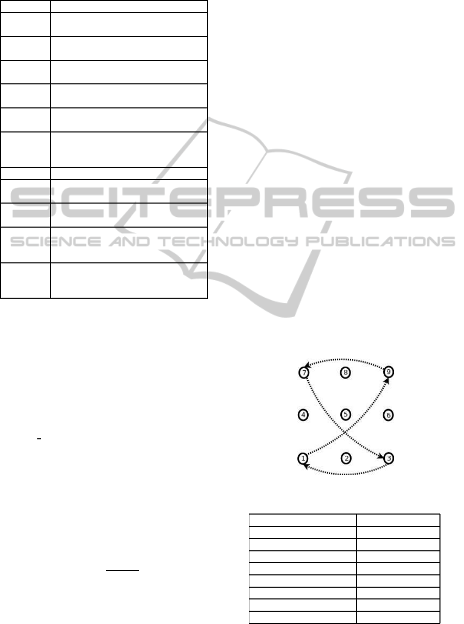
Table 2: Existing Routing Metrics.
Metric Path Selection Criterion
EFT end - to - end delay for all routing
paths
ETX forward and reverse delivery ratios
of the link
ETT forward and reverse delivery ratios
of the link, throughput
ML packet delivery ratio, end-to-end
loss probability
WCETT end - to - end delay and channel di-
versity
MIC forward and reverse delivery ratios
of the link, throughput, inter -flow
interference
ETP expected throughput of the link
mETX losses by means of the bit error
probability
ENT losses by means of the bit error
probability
iAWARE intrerference ratio, forward and re-
verse delivery ratios of the link,
throughput
ETE transmission rate, transmission er-
ror rate, energy consumption rate of
nodes in the network
More specifically, for each node n
i
the residual en-
ergy R(n
i
) is computed as:
R(n
i
) = E
current
(n
i
) − E
con
(n
i
) (3)
where E
current
(n
i
) and E
con
(n
i
) denote the current en-
ergy of the node n
i
and the energy consumed by the
node n
i
, respectively. At the beginning, the current
energy is set to the initial energy of the node.
Since the consumed energy of each node n
i
de-
pends on the state that the node is (i.e. IDLE, TX,
RX, CCA
BUSY, SWITCHING), we use the follow-
ing equation to determine its consumed energy:
E
con
(n
i
) = Current(n
i
) ∗Voltage(n
i
) ∗ Duration (4)
where Current(n
i
) is the current in Ampere and de-
pends on the state in which the node n
i
is, Voltage(n
i
)
voltage is the supply voltage in Volts and Duration is
the interval that passed since the last energy update.
For each node n
i
an energy cost function C(n
i
)is
assigned that is given by:
C(n
i
) =
E
init
(n
i
)
R(n
i
)
(5)
Thus, the total energy cost for a route p from
source node n
S
to destination node n
D
, is given by:
E
p
=
∑
n
i
∈ p, n
i
6= n
D
C(n
i
) (6)
The selected route l will be the one that satisfies
the following property:
E
l
= min{E
p
: p ∈ V} (7)
where V is the set of all the possible routes.
6 SIMULATION RESULTS
The proposed metric (denoted as energy in the fol-
lowing figures) was evaluated using the simulation
software ns-3 (http://www.nsnam.org) and its perfor-
mance was compared only against the ALM (denoted
as airtime in the following figures) since important
implementation details, as well as, simulation param-
eters for the ETE metric are not given. Also the
authors consider that a node consumes energy only
when it transmits or receives data .
We set up our simulation by constructing a grid
topology with N x N mesh STAs. The distance be-
tween two neighboring mesh STAs in the grid was
set to 120 m. In our simulations we generated four
UDP traffic flows among 4 nodes in the network. Fig-
ure 2 shows an illustrative example for the case of a
3 x 3 grid topology. Each simulation run consisted
of 10 iterations, each having the same pair of sender-
destination. Details concerning the simulation param-
eters are given in Table 3.
Figure 2: A 3 x 3 grid topology.
Table 3: Simulation Parameters.
Parameter Value
N 2, 3, 4, 5, 6 and 8
Initial Energy (E
init
) 33 Joules
Interval 0,1 sec
Data rate 150 kbps
Packet size 1024 bytes
Propagation loss model log-distance
Transmission power 18 dbm
Simulation time 25000 sec
WINSYS2013-InternationalConferenceonWirelessInformationNetworksandSystems
218
The residual energy of a node is calculated by the
energy that consumes whenever it is in one of the
states described above. The supply voltage of each
node is set to 3 Volts, while the Duration is set to 1sec.
For each state different current has been set. Table 4
summarizes the current of a node for each state.
Table 4: Energy consumption for each state.
State Current (Ampere)
IDLE 0.00426
CCA BUSY 0.00426
TX 0.0174
RX 0.0194
SWITCHING 0.00426
We used three different quantitative measures
(network lifetime, delay and the Packet Delivery
Fraction (PDF)) to compare the performance of the
three routing metrics. It should be noted that the re-
active mode of the HWMP protocol was used for path
selection, which implies the absence of a root node
in the mesh network used in our simulation scenarios.
Also, as the network lifetime we consider the time
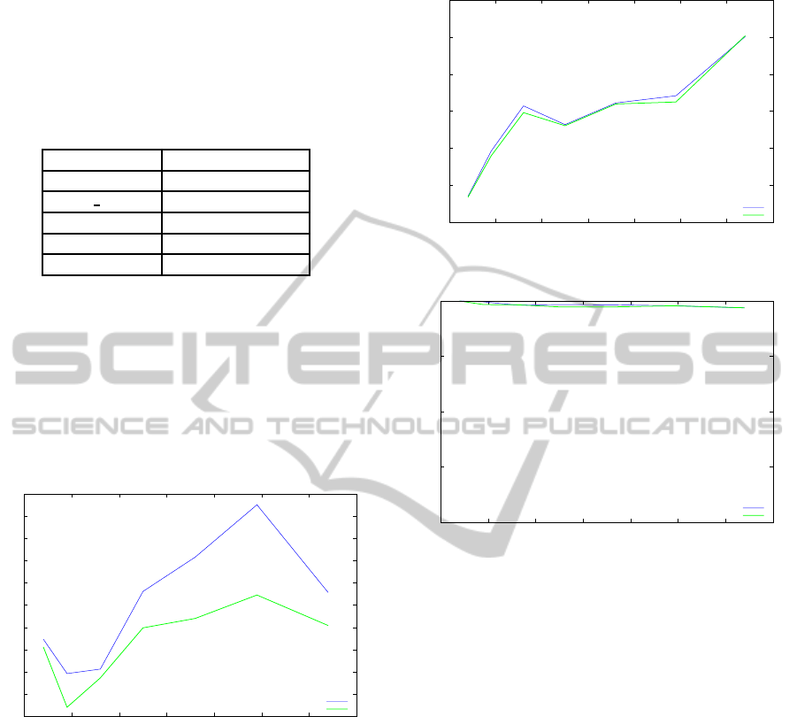
that the first node of the network ran out of energy.
70
80
90
100
110
120
130
140
150
160
170
0 10 20 30 40 50 60 70
Lifetime (min)
# Nodes
Network Lifetime(min)
Energy
Airtime
Figure 3: Lifetime vs # Nodes.
Figure 3 illustrates the network lifetime for each
metric that was applied in the HWMP. As Figure 3
depicts, the proposed metric outperformsthe ALM re-
garding the network lifetime. When the ALM metric
is applied in the HWMP, energy constraints are not
taken into account for the forwarding of data. Thus,
the energy of the nodes along that path is depleted at
shorter time.
In terms of the total delay that the network experi-
ences, as shown in figure 4, the ALM metric achieves
lower delay in comparison with the proposed one.
Since the proposed metric considers the energy con-
straints it should select longer routes than ALM, lead-
ing to a slightly increase in terms of delay.
The last measure that was used for the compari-
0.005
0.01
0.015
0.02
0.025
0.03
0.035
0 10 20 30 40 50 60 70
Delay (sec)
# Nodes
Total Delay(sec)
Energy
Airtime
Figure 4: Total Delay vs # Nodes.
80
85
90
95
100
0 10 20 30 40 50 60 70
pdf (%)
# Nodes
Packet Delivery Fraction(%)
Energy
Airtime
Figure 5: Packet Delivery Fraction vs # Nodes.
son of the three metrics is the Packet Delivery Frac-
tion (PDF), which denotes the percentage of the suc-
cessfully delivered packets. As shown in figure 5, the
PDFs for both merics are quite identical.
7 CONCLUSIONS
In this paper, we have proposed a new routing met-
ric that was incorporated with the HWMP, in place
of the ALM, and applied in a WMN. The proposed
metric calculates an energy cost function by taking
into account the residual energy of nodes in the net-
work and selects the path that minimizes the afore-
mentioned cost function. Simulation results showed
that the proposed metric prolongs the lifetime of a
WMN in comparison with the ALM, while causing
a little higher total delay in the network.
ACKNOWLEDGEMENTS
This work was carried out during the tenure of an
ERCIM ”Alain Bensoussan” Fellowship Programme.
EnergyAwareRoutinginIEEE802.11sWirelessMeshNetworks
219

The research leading to these results has received
funding from the European Union Seventh Frame-
work Programme (FP7 2007-2013) under grant agree-
ment no 246016.
This work is also partly supported by UPRC (Uni-
versity of Piraeus Research Center).
REFERENCES
802.11s 2011/D12.0 (2011). Ieee standard for information
technology – telecommunications and information ex-
change between systems – local and metropolitan
area networks–specific requirements part 11: Wire-
less lan medium access control (mac) and physical
layer (phy) specifications amendment 10: Mesh net-
working. IEEE Std 802.11s-2011 (Amendment to
IEEE Std 802.11-2007 as amended by IEEE 802.11k-
2008, IEEE 802.11r-2008, IEEE 802.11y-2008, IEEE
802.11w-2009, IEEE 802.11n-2009, IEEE 802.11p-
2010, IEEE 802.11z-2010, IEEE 802.11v-2011, and
IEEE 802.11u-2011), pages 1–372.
Bin Ngadi, M., Ali, S., Abdullah, A., and Khokhar, R.
(2012). A taxonomy of cross layer routing metrics for
wireless mesh networks. EURASIP Journal on Wire-
less Communications and Networking, 2012(1):1–16.
Campista, M., Esposito, P., Moraes, I., Costa, L., Duarte,
O., Passos, D., de Albuquerque, C., Saade, D., and
Rubinstein, M. (2008). Routing metrics and protocols
for wireless mesh networks. Network, IEEE, 22(1):6–
12.
Draves, R., Padhye, J., and Zill, B. (2004). Routing in
multi-radio, multi-hop wireless mesh networks. In
MobiCom ’04, 10th annual international conference
on Mobile computing and networking, pages 114–128.
ACM.
Islam, M., Alam, M., Hamid, M., Hong, C., and Lee, S.
(2010). EFT: a High Throughput Routing Metric for
IEEE 802.11s Wireless Mesh Networks. Annals of
Telecommunications, 65(5-6):247–262.
Jin, Y., Miao, H., Ge, Q., and Zhou, C. (2011). Ex-
pected transmission energy route metric for wireless
mesh sensor networks. International Journal of Digi-
tal Multimedia Broadcasting, 2011.
Koksal, C. E. and Balakrishnan, H. (2006). Quality-aware
routing metrics for time-varying wireless mesh net-
works. Selected Areas in Communications, IEEE
Journal on, 24(11):1984–1994.
Mhatre, V., Lundgren, H., and Diot, C. (2007). Mac-aware
routing in wireless mesh networks. In WONS ’07,
Fourth Annual Conference on Wireless on Demand
Network Systems and Services, pages 46–49. IEEE.
Nandiraju, N., Nandiraju, D., Santhanam, L., He, B., Wang,
J., and Agrawal, D. (2007). Wireless Mesh Networks:
Current Challenges and Future Directions of Web-In-
The-Sky. Wireless Communications, IEEE, 14(4):79–
89.
Passos, D., Teixeira, D. V., Muchaluat-Saade, D. C., Mag-
alh˜aes, L. C. S., and Albuquerque, C. V. (2006). Mesh
network performance measurements. In ISMICT ’06,
5th International Information and Telecommunication
Technologies Symposium.
Shyy, D. (2006). Military usage scenario and ieee 802.11s
mesh networking standard. In Military Communica-
tions Conference, 2006. MILCOM 2006., pages 1–7.
IEEE.
Subramanian, A., Buddhikot, M., and Miller, S. (2006). In-
terference aware routing in multi-radio wireless mesh
networks. In WiMesh ’06, 2nd IEEE Workshop on
Wireless Mesh Networks, pages 55–63. IEEE.
Yang, Y., Wang, J., and Kravets, R. (2005). Designing rout-
ing metrics for mesh networks. In WiMesh’05, 1st
IEEE Workshop on Wireless Mesh Networks. IEEE.
WINSYS2013-InternationalConferenceonWirelessInformationNetworksandSystems
220
