
Combining Supervisory Control, Object-oriented Petri-Nets and 3D
Simulation for Hybrid Simulation Systems using a Flexible Meta Data
Approach
Juergen Rossmann, Michael Schluse and Ralf Waspe
Institute for Man-Machine Interaction, RWTH Aachen University, Aachen, Germany
Keywords:
Hybrid Simulation, Meta Data System, Supervisory Control, State Oriented Modeling Language.
Abstract:
The idea of Supervisory Control is to regard a control component (Supervisor) as a discreet event simula-
tion. State Oriented Modeling combines the ideas of supervisory control and object-oriented Petri-nets. With
these concepts as a starting point, our goal was to realize a truly hybrid simulation system, which allows
the simultaneous use of discreet event simulation and continuous 3D-simulation on a unified database. The
key component is an active real-time simulation database, which is an object-oriented, self-reflecting graph
database, with a powerful meta-information system. All nodes are derived from a common base class and
data is stored in properties with standardized getter and setter functions. The object-oriented Petri-nets are
formally described in the State Oriented Modeling Language, which is itself an extension scheme of the sim-
ulation database.
1 INTRODUCTION
State Oriented Modeling (Schluse, 2002) combines
the ideas of supervisory control introduced by (Ra-
madge and Wonham, 1984) and object-oriented Petri-
nets (OPN) (Bastide, 1995). It has already been used
for a large variety of different applications in the field
of simulation (e. g. to simulate robot programs as
described in (Baldini et al., 2005)), but also for the
real-time control of physical systems using simulation
technology as described in (Rossmann et al., 2008).
To realize these applications, Supervisory Control
provides the methods necessary to link the control
algorithms with simulations or physical devices. To
implement the controllers, Petri-nets are known to be
able to map almost all of the most important state
oriented description languages and even modern pro-
gramming paradigms, to model complex scenarios.
Figure 1 illustrates the integration of Supervisory
Control concepts, Petri-Nets and 3D simulation used
so far. Here the simulation system and the supervisory
control are separate entities, working on disjoint sets
of data. Communication between these two sets has
to be established via a mediator.
With this concept as a starting point, our goal was
to realize a truly hybrid simulation system, which
allows the simultaneous use of discreet event sim-
ulation and continuous 3D simulation on a unified
Figure 1: A scene graph based simulation system with an
exterior supervisory control.
database. It is then up to the simulation developer
how to use these paradigms in parallel to realize con-
vincing simulation applications in a wide range of
application areas from ”classical” simulation appli-
cations (driving simulators, virtual production, etc.),
to new application areas like user interface design or
Virtual Testbeds providing simulation-based develop-
ment frameworks for complex systems, a key tech-
nology in the emerging field of eRobotics (Rossmann
and Schluse, 2011).
This paper will detail the progress we have made
in making State Oriented Modeling not only an add-
on to a 3D simulation system, but incorporating the
15
Rossmann J., Schluse M. and Waspe R..
Combining Supervisory Control, Object-oriented Petri-Nets and 3D Simulation for Hybrid Simulation Systems using a Flexible Meta Data Approach.
DOI: 10.5220/0004482400150023
In Proceedings of the 3rd International Conference on Simulation and Modeling Methodologies, Technologies and Applications (SIMULTECH-2013),
pages 15-23
ISBN: 978-989-8565-69-3
Copyright
c
2013 SCITEPRESS (Science and Technology Publications, Lda.)

principles directly into our real time simulation sys-
tem database.
The key component is an active real-time sim-
ulation database, which is an object-oriented, self-
reflecting graph database (as shown in Figure 2).
Figure 2: A simulation system based on an active database
with an exterior supervisory control.
To reach the integration goal outlined above, the
database has to fulfill the following demands:
• The database must support the integration of data
(e. g. 3D simulation data) and algorithms (e. g.
Petri Nets) in one single - now active simulation -
database, supporting interface definition and pro-
viding means for state oriented as well as event
based communication.
• The database must be able to flexibly adopt new
data schemata (e. g. for the representation of var-
ious kinds of OPN) for its internal database, with-
out additional alteration to the core programming.
• For the (real-time) simulation performance it is
important how the data can be accessed and ma-
nipulated by the simulation algorithms (e. g.
to implement even complex controllers using
OPN). Ideally, database management itself should
be time efficient, thus leaving computing power
available to the simulation routines.
• In addition to this, it must be possible to easily
add new simulation algorithms or enhance exist-
ing methods, while guaranteeing stability and per-
formance of the overall system.
• The database itself must be independent from the
type of simulation, to be able to incorporate quasi
continuous as well as discrete event simulation
paradigms into one single integrated simulation
framework as depicted in Figure 3.
The rest of the paper is organized as follows: Af-
ter detailing the architecture of the real-time simula-
tion database in section 2 we discuss an important sys-
tem extension, the plugin providing the basis for 3D
Figure 3: A simulation system based on an active database
with integrated supervisory control.
simulation. In section 3 we then introduce our State
Oriented Modeling Language, its syntax and how it
is integrated into the graph database. To demonstrate
the generality and versatility of our approach we show
a selection of applications in section 4, based on the
database and incorporating State Oriented Modeling.
2 THE REAL-TIME SIMULATION
DATABASE
To fulfill the requirements mentioned in the introduc-
tion, and to eliminate unnecessary dependencies and
provide a sustainable basis for various and diverse
simulation applications, we developed a new archi-
tecture for 3D simulation systems, which is based on
a small (micro-) kernel. This kernel is the Versa-
tile Simulation Database (VSD), a real-time database
containing all the data and algorithms needed for sim-
ulation applications. Fully implemented in C++, it
provides the central building blocks for data man-
agement, meta-information, communication, persis-
tence and user interface. The design of the simula-
tion system as shown in Figure 4 is inspired by the
Object Management Group (OMG) meta model hier-
archy (Kurtev and van den Berg, 2005).
2.1 Meta Information
The uppermost layer (labeled M2 in Figure 4) is the
meta-information system. It is essential for the flex-
ibility, as well as the developer and end user friend-
liness of the database and the simulation system.
The meta-information system is the basis for persis-
tence, user interface, parallel and distributed simula-
SIMULTECH2013-3rdInternationalConferenceonSimulationandModelingMethodologies,Technologiesand
Applications
16

Figure 4: The Meta Model Hierarchy.
tion, scripting and communication. It mainly consists
of the following classes:
• MetaTypeVal. Describes all data types that can
be used as values (e. g. int, double, string, simple
structs, enumerations, flags).
• MetaProperty. Describes a property (see 2.3)
with its getter and setter functions, its data type
and a number of additional flags. These flags de-
scribe the behavior of the property as exposed to
the user (editable, savable, etc.) as well as the
properties ability to be used in parallel and dis-
tributed simulation.
• MetaMethod. Describes a method (member
function) of an instance or a type.
• MetaInstance. Describes an instance includ-
ing its class hierarchy. Each non-abstract meta-
instance is able to create corresponding instances.
Each meta-instance holds a list of the correspond-
ing meta-methods and meta-properties, and fur-
thermore provides a central point for executing
member functions called ”vsdMetaCall”. This
allows the corresponding instance to be used in
generic scripting or parallel and distributed simu-
lation. Messages are sent to instances by calling
predefined methods via the vsdMetaCall function
of the receiving instance.
In addition to ”build-in” classes, it is also possi-
ble to generate meta-instances with the correspond-
ing meta-properties and meta-methods during run-
time (for example for object oriented scripting or new
data models). Such ”run-time meta-instances” are
treated in exactly the same way as the build in meta-
instances. There is no performance overhead in the
data management.
2.2 Instances
The middle layer (labeled M1 in Figure 4) describes
the data model of the simulation. In order to be able
to retain semantic information and integrate data and
algorithms into one single database, the VSD data
model is an object oriented graph database (Gyssens
et al., 1994), whose structure is detailed in this sec-
tion. A simplified class hierarchy of the VSD core is
shown in Figure 5.
Figure 5: The core database class hierarchy.
All nodes in the graph database, the database itself
and even the simulation environment are derived from
a single base class called ”Instance”. This base class
provides mechanisms for inter-instance communica-
tion, as well as access to the meta-information system,
which allows introspection of class hierarchy, proper-
ties and methods (see 2.1).
The simulation model (labeled M0 in Figure 4) is
an instantiation of the data model.
2.3 Properties
Derived form the instance class is the ”SimStateIn-
stance”. Besides providing a reference to its simula-
tion state (see 2.4) it may contain so called ”Proper-
ties” and encapsulates the access to them. Properties
are standardized getter and setter functions that en-
capsulate the data itself. All data in the simulation
system is stored as properties. Properties can encap-
sulate any single value or value containers (lists, vec-
tors, etc.), whose data types are known to the meta-
information system. Properties can also hold refer-
CombiningSupervisoryControl,Object-orientedPetri-Netsand3DSimulationforHybridSimulationSystemsusinga
FlexibleMetaDataApproach
17

ences or lists of references. References come in two
different varieties, composite aggregation (with refer-
ence counting as described in (Levanoni and Petrank,
2006)), and shared aggregation. All parent child rela-
tions within the database are implemented as compos-
ite aggregation references. Shared aggregation refer-
ences do not change the reference counter of the in-
stance, but are informed if the instance gets deleted.
2.4 Database Structure
As shown in Figure 5 all nodes in the graph database,
as well as the database itself are derived from the in-
stance base class.
• Environment and Simulation States. The com-
plete simulation is described by an ”Environ-
ment”, which contains at least one ”Simulation
State” (SimState). Simulation states provide
mechanisms for copying content from one state to
another and are thus the basis for data partition-
ing in distributed or parallel simulation. For this,
a simulation state can keep a list of all transac-
tions, which can then be used to apply all bundled
state changes to another simulation state on the
same or on other computers. For example, when
streaming data from an external database a sepa-
rate thread with its own simulation state does han-
dle the database interface. When the data has been
loaded it will be transfered into the main simula-
tion state.
• Container and Element Index. The database
graph itself is kept by a ”Container” class, a col-
lection of graph nodes. A special container is
the ”Database” class, which acts as the span-
ning tree of the database. Other containers can
be constructed, offering a different ”View” onto
the database, by rearranging all nodes or a subset
thereof in different order. An example for this is
the spatial view, which shows nodes in their spa-
tial arrangements and gets updated when objects
are grabbed or moved by other objects.
Furthermore the database offers convenience ac-
cess to specific instance types via the ”ElementIn-
dex” class, which for every meta-instance pro-
vides a list of all instances of that type. By
this mechanism it is possible to view the graph
database in a traditional table based manner with-
out performance restrictions.
• NamedModelInstances. This derivation from
SimStateInstance provides a name property, as
well as a list of extensions.
• Nodes. Most commonly used is the ”Node” class,
which adds a child reference list property to the
”NamedModelInstances” class.
• Extensions. ”Extensions” are used to add data
and functionality to a variety of nodes. Extensions
can not only be attached to nodes, but also to other
extensions.
2.5 Active Database
As mentioned above the VSD is not only a static
data container but also contains the simulation algo-
rithms itself. The environment, as well as all con-
tainers and element indexes actively inform interested
listeners about new instance creation or deletion, as
well as property modifications. Furthermore each in-
stance sends a signal when one of its properties has
been changed. Thus interested parts of the simula-
tion systems can be informed about state changes in
the simulation, eliminating the need to continuously
poll the database content. With the active messag-
ing system and the availability of element index lists
we have minimized the need for data polling and tree
traversal. By creating derived classes (like ”Actua-
tor”, ”Sensor”, ”Robot”, etc.) from the Node or Ex-
tension base class, the simulation algorithms (actuator
control, sensor simulation, robot controller, etc.) it-
self are integrated into VSD. Simulation algorithms
that need a complete overview over the simulation
state (like rigid body simulations) are integrated on
the database level but still manage their data on the
node and extensions level as illustrated before.
That’s why we call the VSD active. To achieve
a complete decoupling of the different system com-
ponents with well defined interfaces (introspectable
using the meta-information system), methods are pro-
vided for event as well as state based communication.
These methods can be used to let the components ex-
change information as defined by the algorithm devel-
oper or the simulation expert.
2.6 3D Simulation
As already stated above, even the 3D simulation ca-
pabilities are an extension of the core database. An
excerpt of class hierarchy for these classes is shown
in Figure 6.
The data for 3D simulation may be interpreted by
a collision detection system, a kinematic animation
system, the physics simulation, the renderer or other
application specific simulation algorithms. The most
important classes are:
• 3D Node. A node which contains a frame prop-
erty describing its position and orientation relative
to the parent node.
SIMULTECH2013-3rdInternationalConferenceonSimulationandModelingMethodologies,Technologiesand
Applications
18

Figure 6: Add-ons to the core database (white): components
for 3D simulation (blue).
• Hull Node. A 3D node that holds a reference to
geometry. It also has a reference list of map nodes
and an associated material node.
• Geometries. This instance holds all data neces-
sary to describe a geometry. Properties include
vertex, facet and texture coordinate lists. It can be
referenced (shared) from many hulls.
• Maps and Materials: A map is a node with an url
to a texture. Furthermore the function of the tex-
ture is given (for example: color map, normal map
or diffuse map). A material node describes physi-
cal properties of a geometry, like color or electric
conductivity. Maps and material are not only used
for rendering. For example it is possible to attach
a radar reflection intensity map to a hull node,in
order to enable a more realistic radar simulation.
2.7 Simulation System
For real-world applications the database must be ex-
tended by new data schemes and simulation algo-
rithms like 3D simulation (VSD3D, see section 2.6)
or State Oriented Modeling (VSDNet, see section 3).
This concept is illustrated in Figure 7.
Further functionality like rendering, data process-
ing, file loading, hardware interfaces or simulation
scheduling, is handled by plugins, which may also
add database enhancements like kinematics, dynam-
ics (detailed in (Jung, 2011)), process simulation or
GIS (Geo Information Systems, see (Longley et al.,
2005)).
Figure 7: The micro-kernel architecture. All plugins are
able to freely communicate with the core and with each
other.
3 STATE ORIENTED MODELING
LANGUAGE
In this section we introduce the features of the ”State
Oriented Modeling language” (SOML++) and show
how object oriented Petri-nets are integrated into our
simulation system. As mentioned before, the goal was
to make State Oriented Modeling and Petri-nets an
integral part of the simulation system.
3.1 Supervisory Control
This basic concept to integrate Petri-nets with 3D sim-
ulation systems is based on the Supervisory Control
approach. The idea of Supervisory Control describes
a technique to regard a control component (Super-
visor) as a discrete-event simulation (DES), with its
own state space and transitions caused by events that
reflect changes at observed outputs of the controlled
system (Plant). Figure 8 shows the basic structure of
Supervisory Control: selected, re-fed state transitions
σ of the plant generate events, which trigger further
state transitions in the supervisor. Based on those
state transitions, the supervisor can react, in order to
adjust the plant with control commands γ.
Figure 8: The basic structure of Supervisory Control, where
one DES (Supervisor) commands another DES (Plant).
With respect to the focus of this paper, the inte-
gration of Petri-Nets and 3D Simulation, Petri Nets
are used to implement the control component (Super-
CombiningSupervisoryControl,Object-orientedPetri-Netsand3DSimulationforHybridSimulationSystemsusinga
FlexibleMetaDataApproach
19
visor) as a DES supervising and controlling the 3D
simulation (Plant).
3.2 Language Features
SOML++ is a language that describes objects that can
contain Petri-nets (see (Bastide, 1995)). In an object-
oriented fashion these objects can be derived from
other objects and can encapsulate data.
In the global name-space all the language con-
structs described below are allowed.
• Object-classes. An object-class must be instanti-
ated as an object in order to be used. It is possible
to subclass any object-class, regardless whether
it has been defined in the SOML++ code or is a
build-in class like VSD3D::Node.
• Objects. An object can be created from scratch
or it can be derived from any object-class. Objects
can be constructed with arguments, which will get
passed to the constructor function.
An object or object-class may contain any number of
further objects or object-classes. Additional language
elements and the building blocks of Petri-nets for use
within objects or object-classes are:
• Properties. A value of all data types, that are
known to the meta-information system of the sim-
ulation. Properties can also hold references to
SOML++ objects.
• Functions. A block of code to be executed.
Like in C++, a function has any number of argu-
ments and a defined return type. Functions can
be called from other functions or transitions any-
where within the SOML++ script.
• Places. A place as defined for a traditional Petri-
net. Places and transitions are special objects,
thus it is possible to define properties or functions
within them.
• Transitions. Transitions may contain conditions
and actions. If the conditions are met a marker
may pass the transition and the actions are exe-
cuted. Both, conditions and actions, are defined
by user defined code which may in turn call other
functions. During code execution, the ”mark”
context is known, representing the mark object
currently testing or traversing the transition.
• Arrows. Link places to transitions and transitions
to places.
• Start-place. Declares the object containing this
statement to be a token, which moves through the
Petri-net as defined by places, arrows and transi-
tions (in the example: each DEMO instance be-
comes a token accessible by the mark statement
in transitions).
This short summary outlines only a few language
elements. In addition to this, the Petri-net imple-
mentation of State Oriented Modeling provides arrow
conditions, different arrow types (normal, inhibitor,
communication), Petri-net substitution and invocation
hierarchy with arguments and return values, to name
only the most important features.
3.3 Interpreting and Executing
SOML++ Code
For the representation of the SOML++ code
within the simulation database, a new data schema
”VSDNet” as described in Figure 9 has been devel-
oped, providing classes for all SOML++ language el-
ements.
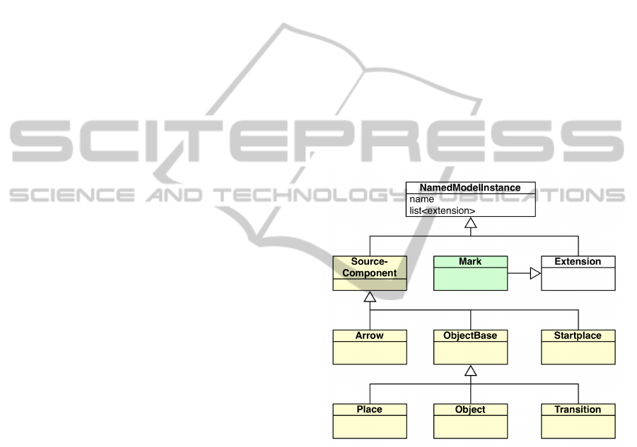
Figure 9: Add-ons to the core database (white): components
for state oriented modeling (yellow and green).
When a piece of SOML++ code is loaded
by the simulation system, equivalent VSDNet
”SourceComponent”-instances are created for
classes, objects, arrows, etc. After that, the source
representation in the simulation database is traversed
and meta-instances (see Section 2.1) are generated
for each object-class and each object. Properties are
mirrored as meta-properties and functions as meta-
methods. Afterwards new instances (see Section 2.2)
are created from this meta-data and added to the
database. Contained places and transitions are sub
nodes of the object nodes, arrows are modeled as sub
nodes of the originating place and transition nodes.
Since every SOML++ object has now become a
SIMULTECH2013-3rdInternationalConferenceonSimulationandModelingMethodologies,Technologiesand
Applications
20

Figure 10: A Virtual Testbed. (Spaceclimber Model - Copyright DFKI Bremen).
”normal” database node, net functions can use all
the functionality provided by the database or the
meta-information system, respectively. Net functions
can interact with the rest of the database by creating
new instances (using not only those defined in the
SOML++ code, but all classes known to the simu-
lation system ), obtain references to other database
nodes and call functions of these nodes.
Of course other database nodes can interact in the
same way with the net objects, for example signals are
sent when a net object is created or a property within
this object has changed. There is no additional inter-
face layer between the core database and the Petri-
nets - the Petri-nets are an integral part of the simula-
tion database.
Our simulation system also provides a compre-
hensive set of SOML++ debugging tools. All tokens
can be traced and it is possible to set breakpoints
within functions. Upon reaching a breakpoint a call
stack and a list of local variables is available.
3.4 Realizing Supervisory Control
At this point, all components necessary for realiz-
ing Supervisory Control with State Oriented Model-
ing technique in 3D simulation systems are available.
Using the same concepts, Petri-nets can observe any
simulation state. State changes cause transitions to
”fire” (representing events σ) which produce control
commands γ.
4 APPLICATIONS
The hybrid simulation approach presented in this pa-
per greatly simplifies the realization of new 3D sim-
ulation applications. Nearly all the applications real-
ized so far benefit this approach. They use quasi con-
tinuous simulation technology to simulate kinemat-
ics, physics, actuators, sensors, various processes, etc.
and State Oriented Modeling for supervisor and con-
troller implementation, interfaces, user interaction,
and supervisory control of the overall simulation. In
this section we will focus on two application areas
illustrating the application range of the concept pre-
sented above.
4.1 Virtual Testbeds
Using the concepts illustrated above we are now able
to simulate complex systems with all relevant sys-
tem components and their interdependencies. The re-
sult is a comprehensive development and testing en-
vironment based on simulation technology, a Virtual
Testbed (see Figure 10).
The Virtual Testbed concept is a key technology
CombiningSupervisoryControl,Object-orientedPetri-Netsand3DSimulationforHybridSimulationSystemsusinga
FlexibleMetaDataApproach
21

in the emerging field of eRobotics, because Virtual
Testbeds can act as a central focal point in multi-
disciplinary development projects. For this reason,
the first application areas of Virtual Testbeds are in
the field of robotics, i. e. for the development of ex-
ploration robots, production plants or other complex
systems.
4.2 Simulation based Control
The use of supervisory control and state oriented
modeling is not confined to the virtual world. The
very same concept can also be applied to control
real hardware with the same software. We are us-
ing simulation technology to directly control physical
systems, which we call ”Simulation-Based Control”
(Rossmann et al., 2012). This way, the same simula-
tion and algorithms which were prototyped in a Vir-
tual Testbed, control the actual hardware afterwards.
An example is the control system of the multi-robot
workcell depicted in Figure 11 consisting of two re-
dundant 8-axis robots (linear axis plus a 7-axis robot).
Figure 11: Simulation Based Control of a robot work cell.
For robot control the database of our simulation
system is extended with new types of node extensions,
able to model and control kinematic chains and kine-
matic trees. The extension supports rotary and pris-
matic joints, as well as universal joints and joints di-
rectly defined via their Denavit-Hartenberg parame-
ters.
The control concept of the multi robot system is
based on the Intelligent Robot Control System (IRCS)
structure, developed and introduced in the 1990s by
(Freund and Rossmann, 1995). The IRCS addresses
the main aspects of multi robot control by breaking
up given tasks into smaller, manageable pieces in a
”divide and conquer” fashion, delegating control over
several layers of abstraction and responsibility. Fig-
Figure 12: The Intelligent Robot Control System.
ure 12 shows a simplified structure for the robot con-
troller.
Here, the 3D simulation control (named ”Multi
Robot Control”) acts as a coordinator of the ven-
dor specific robot control units by implementing
the simulation-based control concept. To commu-
nicate with the physical devices, the Ethernet based
Fast-Research-Interface (FRI) is used for the KUKA
Light-Weight-Robots (Bischoff et al., 2010), while a
Profibus-Interface is used for the linear axes. The
user interaction via a ”User Interface” and the real-
time robot coordination ”Multi Robot Control” is per-
formed on different computers, both running the same
simulation system, though with different configura-
tions on different operating systems (Windows and
QNX). Both simulations use the same model, which
is kept in sync between the computers by distribution
methods provided by the core database.
The ”Meta Control” layer (action generation and
distributed planning using algorithms from the field
of artificial intelligence), as well as the ”Multi Robot
Control” layer are Supervisory Controls implemented
in SOML++.
5 CONCLUSIONS AND FUTURE
WORK
In this paper we presented a new structure for an ob-
ject oriented graph database for versatile 3D simula-
tion systems. Due to their meta-information manage-
ment, such systems can adapt to new data schemes
even at run-time of the simulation, without the need
for further programming. This approach allows us
to integrate Petri-net objects as modeled in the State
Oriented Modeling language. These Petri-net objects
become an integral part of the simulation database
and have full access to the 3D simulation data and
algorithms, which enables supervisory control of
quasi continuous simulation applications using dis-
SIMULTECH2013-3rdInternationalConferenceonSimulationandModelingMethodologies,Technologiesand
Applications
22

crete event simulations. The result is a hybrid simula-
tion system which has proven its applicability in large
variety of applications, ”classical” simulation appli-
cations like driving or production simulators, but also
new fields of applications like GUI modeling or Vir-
tual Testbeds.
Although performance of the interpreted
SOML++ code segments never was a problem
so far, we plan to introduce a compiler, which will
transfer the generated meta-instances into native C++
code. In addition to this we plan the integration of
further Petri-net approaches like hybrid and contin-
uous petri nets (Alla and David, 1998) to widen the
methodical base of the overall concept.
REFERENCES
Alla, H. and David, R. (1998). Continuous and hybrid petri
nets. Journal of Circuits, Systems and Computers,
08:159–188.
Baldini, F., Bucci, G., and Vicario, E. (2005). A tool
set for modeling and simulation of robotic workcells.
In Techniques, Methodologies and Tools for Perfor-
mance Evaluation of Complex Systems, 2005. (FIRB-
Perf 2005). 2005 Workshop on.
Bastide, R. (1995). Approaches in unifying petri nets and
the object-oriented approach. In In Proceedings of the
Application and Theory of Petri Nets.
Bischoff, R., Kurth, J., Schreiber, G., Koeppe, R., Albu-
Sch
¨
affer, A., Beyer, A., Eiberger, O., Haddadin, S.,
Stemmer, A., Grunwald, G., and Others (2010). The
kuka-dlr lightweight robot arm - a new reference plat-
form for robotics research and manufacturing. In In-
ternational Symposium on Robotics (ISR2010).
Freund, E. and Rossmann, J. (1995). Systems approach to
robotics and automation. In Robotics and Automation,
1995. Proceedings., 1995 IEEE International Confer-
ence on.
Gyssens, M., Paredaens, J., van den Bussche, J., and van
Gucht, D. (1994). A graph-oriented object database
model. Knowledge and Data Engineering, IEEE
Transactions on, 6:572 –586.
Jung, T. (2011). Methoden der Mehrkrperdynamiksimu-
lation als Grundlage realittsnaher Virtueller Welten.
PhD thesis, Institue For Man-Machine Interaction,
RWTH Aachen University, Germany.
Kurtev, I. and van den Berg, K. (2005). Mistral: A language
for model transformations in the mof meta-modeling
architecture. In European MDA Workshops: Foun-
dations and Applications, MDAFA 2003 and MDAFA
2004, Twente, The Netherlands, June 26-27, 2003 and
Link
¨
oping, Sweden, June 10-11, 2004. Revised Se-
lected Papers.
Levanoni, Y. and Petrank, E. (2006). An on-the-fly
reference-counting garbage collector for java. ACM
Trans. Program. Lang. Syst., 28:1–69.
Longley, P. A., Goodchild, M. F., Maguire, D. J., and Rhind,
D. W. (2005). Geographical Information Systems and
Science. Wiley.
Ramadge, P. and Wonham, W. (1984). Supervisory control
of a class of discrete event processes. In Analysis and
Optimization of Systems. Springer Berlin / Heidelberg.
Rossmann, J. and Schluse, M. (2011). Virtual robotic
testbeds: A foundation for e-robotics in space, in in-
dustry - and in the woods. In Developments in E-
systems Engineering (DeSE), 2011.
Rossmann, J., Schluse, M., Schlette, C., and Waspe, R.
(2012). Control by 3d simulation - a new erobotics
approach to control design in automation. In Intelli-
gent Robotics and Applications. Springer Berlin Hei-
delberg.
Rossmann, J., Schluse, M., and Waspe, R. (2008). 3d dis-
crete event systems: An efficient way to model and su-
pervise dynamic behavior in virtual environments. In
ASME 2008 International Design Engineering Tech-
nical Conferences and Computers and Information in
Engineering Conference (IDETC/CIE2008), volume
2008, pages 1503–1511. ASME.
Schluse, M. (2002). Zustandsorientierte Modellierung in
Virtueller Realitt und Kollisionsvermeidung. PhD
thesis, Institue Of Robotics Research, University Of
Dortmund, Germany.
CombiningSupervisoryControl,Object-orientedPetri-Netsand3DSimulationforHybridSimulationSystemsusinga
FlexibleMetaDataApproach
23
