
Architecture Level Prediction of Software Quality Attributes
Imen Derbel
1
, Lamia Labed Jilani
1
and Ali Mili
2
1
Institut Superieur de Gestion, Bardo, Tunisia
2
New Jersey Institute of Technology, 07102-1982 Newark, NJ, U.S.A.
Keywords:
Software Architecture, Architecture Description Language, Acme, Quality Attributes, Response Time,
Throughput.
Abstract:
The concept of software architecture emerged in the eighties as an abstraction of all the design decisions
pertaining to broad system structure, component coordination, system deployment, and system operation. As
such, software architecture deals less with functional attributes than with operational attributes of a software
system. So much so that a sound discipline of software architecture consists in identifying and prioritizing
important non functional attributes that we want to optimize in the software system, and using them as a
guide in making architectural decisions. We know of no architectural description language that allows us
to represent and reason about non functional quality attributes such as response time, throughput, failure
probability, security, availability, etc. In this paper, we present a modified version of ACME, and present a
compiler of this language that allows us to analyze and reason about non functional attributes of software
systems.
1 INTRODUCTION
The concept of software architecture has emerged
in the eighties as an abstraction of the design de-
cisions that precede functional design, and pertain
to such aspects as broad system structure, system
topology in terms of components and connectors, co-
ordination between system components, system de-
ployment, and system operation (Garlan and Shaw,
1996)(L. Bass, 2003). This concept has gained fur-
ther traction through the nineties and the first decade
of the millennium, by virtue of its role in many
modern software engineering paradigms, such as do-
main engineering, product line engineering, compo-
nent based software engineering, and COTS based
software development (Frakes and Kang, 2007)(Gun-
ther, 1998)(Luckham et al., 2000). Whereas func-
tional design and programming determine the func-
tional attributes ofa software product, the architecture
of a software product determines its non-functional
attributes, i.e. properties such as: response time,
throughput, failure probability, buffer capacity, avail-
ability, security, safety, etc; we refer to these as qual-
ity attributes of the software product. A number
of architecture description languages (ADL’s) have
emerged in the past two decades, including ACME
(CMU) (Garlan et al., 1997), Wright (CMU) (Allen,
1997), Rapide (Stanford University) (Luckham et al.,
2000), SADL (SRI) (Moriconi et al., 1995), Ae-
sop (CMU) (Garlan et al., 1994), MetaH (Honey-
well) (Vestal, 1996), C2 (UC Irvine) (Medvidovic
et al., 1996), PADL (Urbino) (Aldini and Bernardo,
2005)(Aldini et al., 2010), Unicon (CMU) (Shaw
et al., 1995). Even though many of these languages
embody state of the art ideas about software architec-
tures, and despite the importance of non functional
attributes in the characterization of software archi-
tectures, to the best of our knowledge none of these
ADL languages offers automated support for analyz-
ing quality attributes of software architectures. In this
paper we propose to fill this gap by proposing an ADL
which is a modified version of ACME (we refer to this
languageas ACME+), and building a compiler for this
language, with the following characteristics:
• ACME+ is based on ACME’s architecture ontol-
ogy, in that it represents architectures in terms of
components, connectors, ports and roles.
• It uses ACME’s
property
construct to represent
the quality attributes of components and connec-
tors; but while ACME considers the data entered
under
property
as a mere comment, which it
does not analyze, we give it a precise syntax and
use it in our analysis.
15
Derbel I., Labed Jilani L. and Mili A..
Architecture Level Prediction of Software Quality Attributes.
DOI: 10.5220/0004416800150024
In Proceedings of the 8th International Conference on Evaluation of Novel Approaches to Software Engineering (ENASE-2013), pages 15-24
ISBN: 978-989-8565-62-4
Copyright
c
2013 SCITEPRESS (Science and Technology Publications, Lda.)

• Whereas ACME lists the ports of a component
and the roles of a connector, and does not specify
any relation between the ports of a component or
the roles of a connector, we introduce special pur-
pose constructs that specify these relations, and
use them in our analysis.
• Whereas programming language compilers gen-
erate executable code that represents the func-
tional attributes of a software product; our com-
piler reads the architecture of a system written
in ACME+ language and generates equations that
characterize the non-functional attributes of the
product. These equations are written as Mathe-
matica (Wolfram Research) equations. We then
use Mathematica to analyze and solve these equa-
tions.
Among the questions that we envision to address/ an-
swer, we cite the following:
• Given a set of values for the quality attributes of
components and connectors, what are the values
of the quality attributes of the overall system?
• How do the system-wide attribute values depend
on component-level and connector-level values?
• How sensitive are system-wide attribute values to
variations in component-leveland connector-level
values?
• Which component-level or connector-level at-
tribute values are causing a bottleneck in system
wide attribute values?
In section 2, we briefly present and motivate the main
syntactic features that we have added to ACME; in
section 3, we discuss the semantics of these con-
structs, in terms of Mathematica equations that we
associate to them. In section 4, we discuss the gen-
eration of a compiler that reads product architectures
written in ACME+ and translate them in terms of
equations which will allow the analysis of the archi-
tecture through a user interface. In section 5, we dis-
cuss related work. The paper concludes in section 6
by a discussion of our prospects for future research.
2 ACME+: SYNTAX
In order to enable us to represent and reason about
non functional properties of software architectures,
we need an architectural description language that of-
fers the following features:
1. Support the ability to represent components, con-
nectors, ports and roles.
2. Support the ability to represent quantitative non
functional attributes of components and connec-
tors.
3. Provide constructs that enable us to represent op-
erational information that impacts the non func-
tional attributes. At a minimum, we must be able
to identify, among ports of a component (and roles
of a connector) which ports are used for input and
which ports are used for output. Furthermore, if
we have more than one input port or more than
one output port, we need to represent the relation
between the ports: are they mutually synchronous
or asynchronous? Do they carry duplicate infor-
mation? or disjoint/ complementary information?
or overlapping information?
4. Provide means for a component (or a connector)
to represent more than one relation from input
ports (roles) to output ports (roles). The reason
we need this provision is that often the same com-
ponent (or connector) may be involved in more
than one operation, where each operation involves
a different configuration of ports (roles), and have
different values for its non functional attributes.
Among all the architecture description languages that
we have considered, we have found none that meets
these fourrequirements. Most languages devotemuch
attention to representing the topology of the system;
some languages, such as Wright (Allen, 1997) and
PADL (Aldini et al., 2010) complement the topologi-
cal information with operational information, but the
latter is expressed in CSP (Hoare, 2004) which is too
detailed for our purposes, and at the same time fails
to always provide the information we need. To cater
to the four requirements we have presented above, we
adopt ACME’s basic syntax and ontology, and add to
it the concept of
functional dependency.
2.1 ACME+: ACME Extension with
Functional Dependency
We adopt ACME’s ontology of components, connec-
tors, ports and roles, and its main approach for rep-
resenting software architectures. This approach rep-
resents components by describing a number of their
properties, including a list of their relevant ports; and
it represents connectors by describing their proper-
ties, including a list of their relevant roles (Garlan and
Schmerl, 2006). Furthermore, ACME enables the ar-
chitect to build arbitrary topologies by means of at-
tachment statements, which connect ports to role and
roles to ports. The ACME code below shows a simple
ACME description of a client-server architecture:
ENASE2013-8thInternationalConferenceonEvaluationofNovelSoftwareApproachestoSoftwareEngineering
16

System simpleCS = {
Component client = {Port call_rpc; };
Component server = { Port rpc_request; };
Connector rpc = { Role client_side;
Role server_side; };
Attachments = {
client.call_rpc to rpc.client_side;
server.rpc_request to rpc.server_side; }}
In order to enable us to represent and reasonabout non
functional properties of software architectures, we en-
rich ACME ADL with a new construct which must
support the following capabilities:
• Specify the operational information of a software
architecture that impacts the non functional at-
tributes.
• Identify the input ports and output ports of a com-
ponent, as well as the origin roles and destination
roles of a connector.
• Represent relations between ports of the same
type (input, output) and between roles of the same
type (origin, destination).
• Represent non functional properties of compo-
nents and connectors from a predefined catalog,
using predefined units of measurement (e.g. mil-
liseconds for response time, transactions per sec-
ond for throughput, probability for failure proba-
bility, hours for MTTF (Mean Time To Fail), per-
centage for availability).
The BNF syntax of the proposed construct is defined
as follows:
FuncDependency ::= FunDep ":" "{" Rdeclaration
"}" ";" ;
Rdeclaration ::= Rdecl Rdeclaration |;
Rdecl ::= Identifier "(" Inputs ";"
Outputs ";" Properties ")";
Inputs ::= Input "(" InputSpecification ")"|;
Outputs ::= Output "(" OutputSpecification ")"|;
InputSpecification ::= InSelection "("
InSynchronisation "(" ListId ")" Spec ")"
| InSynchronisation "(" Identifier ")" ;
InSelection ::= AnyOf | AllOf | MostOf ;
InSynchronisation ::= Synchronous|Asynchronous;
OutSelection ::= Duplicate|Exclusive|Overlapping;
OutSynchronisation ::= Simultaneous|Asavailable ;
ListId ::= Identifier "," ListId | Identifier;
Spec ::= "," InputSpecification Spec | ;
OutputSpecification ::= OutSelection "("
OutSynchronisation
"(" ListId ")" ")"|;
Properties ::=Properties "(" PropSpecification ")"
| ;
PropSpecification ::= PropSpecification PropSpec|;
PropSpec ::= procTime "=" PTvalue ";"
| thruPut "=" TPvalue ";"
| failProb"=" FPvalue ";"
PTvalue ::= Literal sec | Literal msec;
TPvalue ::= Literal trans/sec
| Literal trans/min;
FPvalue ::= Literal ;
In the construct
FuncDependency
, FunDep is a
reserved word which serves as a header indicat-
ing that the following descriptions pertain to func-
tional dependency relations of the component in
question. This construct consists of one or more
functional relations (
Rdeclaration
). Each relation
(
Rdecl
) is identified by a Relation Name and cor-
responds to a possible role played by the compo-
nent. It connects Input Ports (
Inputs
) and Output
Ports (
Outputs
) and is characterized by non func-
tional properties (
Properties
) such as processing
time, throughput, and failure probability. The term
Input is a reserved word which indicates the list of
input ports and their operational information through
InSelection
and
InSynchronisation
constructs.
The term
InSelection
indicates whether all of the
input ports are needed (AllOf), or any one of them
is sufficient (AnyOf), or most of them are needed
(MostOf), as would be the case in a modular re-
dundancy voting scheme for example. The term
InSynchronisation
indicates whether the ports
have to make data available Synchronously or Asyn-
chronously. Similarly the term Output is a reserved
word which indicates the list of output ports and
their operational information through
OutSelection
and
OutSynchronisation
constructs. The term
OutSelection
indicates whether the outputs posted
on the different output ports are duplicate, exclusive
or overlapping. The term OutSynchronisation indi-
cates whether the data posted on output ports is posted
simultaneously on all output ports (Simultaneous),
or is posted as available (Asavailable). The term
Properties is a reserved word which indicates the
non functional properties of the component. So far,
we have restricted the property names to procTime,
thruPut and failProb. For each property, we spec-
ify its value respectively through the terms
PTvalue
,
TPvalue
and
FPvalue
. The above rules form the ba-
sis of the proposed extensions. The rules can, how-
ever, be extended to include multiple requirements
and information where necessary. In order to illus-
trate the proposed extensions in practice, we present
an example in the next section.
2.2 A Sample Example of an
Architecture Description with
ACME+
To illustrate how the proposed construct works, we
consider the architecture of the Aegis Weapons Sys-
tem (Allen, 1997).
ArchitectureLevelPredictionofSoftwareQualityAttributes
17
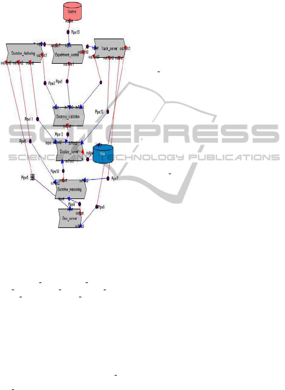
Figure 1: Aegis system architecture represented in ACME
Studio.
Figure 1 depicts the basic architecture of Aegis
represented in ACME Studio (Schmerl and Gar-
lan., 2004). The system consists of seven com-
ponents: Geo
Server, Doctrine Reasoning, Doc-
trine
Authoring, Track Server, Doctrine Validation,
Display Server and Experiment Control. To this con-
figuration, we add, for the sake of illustration, two
dummy components Sink and Source and their as-
sociated connectors. Using our proposed constructs
of functional dependency, we give below examples
of ACME+ description. For the sake of brevity, we
content ourselves with giving ACME+ descriptions of
only two components of Aegis system. The overall ar-
chitecture description of the Aegis Weapon System in
ACME+ is available online at:
http://web.njit.edu/∼mili/AegisArch.txt.
The first description is relative to Display
Server
component and the second one describes Doc-
trine
Authoring component.
Component Display_Server {
Port inPort0; Port inPort1;
Port inPort2;Port inPort3;
FunDep = {R(
Input(AllOf(Synchronous(inPort0; inPort1;
inPort2; inPort3)));
Output(outPort);
Properties(procTime=1;thruPut=0.4;failProb=0.3)
)}};
The first example provides that the component Dis-
play Server operates in only one task (
R
) that requires
all of data provided by the input ports synchronously
in order to display results on its output port. This task
is characterized by quality attributes defined in terms
of processing time, throughputand failure probability.
Component Doctrine_Authoring {
Port inPort; Port outPort0;
Port outPort1; Port outPort2; Port outPort3;
FunDep= {R(
Input(inPort);
Output(Duplicate(Simultaneous(outPort1; outPort0;
outPort2; outPort3)));
Properties(procTime= 0.7;thruPut=0.2;failProb=0.2)
)}};
The second example provides that the component
Doctrine Authoring operates in only one task (
R
) that
requires the data produced by the input port in order to
display results by its output ports. These output ports
send duplicate information simultaneously. This task
is characterized by quality attributes defined in terms
of processing time, throughputand failure probability.
To test the adequacy of this languages, we have used it
to represent a number of sample architectures, includ-
ing the Video Animation Repainting System (Bonta,
2008),and the Rule Based System (Garlan and Shaw,
1996). In all cases we find that the information re-
quired by the Acme+ description is readily available
as part of the architectural description.
3 ACME+: Semantics
3.1 A Logical Framework
In order to use the information recorded in the pro-
posed constructs for the purpose of analyzing soft-
ware architectures, we take the following modeling
decisions:
• Each port in a component is labeled for inPort or
for outPort.
• Each role in a connector is labeled as a fromRole
or a toRole.
• Each architecture has a single component without
input port, called the Source, and a single compo-
nent without output ports, called the Sink.
ENASE2013-8thInternationalConferenceonEvaluationofNovelSoftwareApproachestoSoftwareEngineering
18

In this discussion, we are interested in three sam-
ple non-functional attributes, namely: (1) Response
time, measured in milliseconds. We assume that each
component has a property of type real called proc-
Time that represents the component’sprocessing time
and each connector has a property of type real called
transTime that represents the connector’s transmis-
sion time. (2) Throughput, measured in transactions
per second. We assume that each component and
each connector has a property of type integer called
thruPut. (3) Failure probability, measured as a prob-
ability. We assume that each component and each
connector has a property of type real called failProb.
We define the system wide attributes as:
• For each port and each role, we assign a set of
attributes that are related to the quality attributes
we are interested in. Hence each port has a re-
sponse time attribute called RT, a throughput at-
tribute called TP, a failure probability attribute
called FP (for failure probability). We distin-
guish between component and connector proper-
ties, which are specified in the ACME+ source
code, and the (similar sounding but distinct) port
and role attributes, which are assigned to ports
and roles by our attribute grammar, and are com-
puted by our compiler.
• For the output port of the source component, we
assign trivial values for these attributes, such as
zero for the response time, zero for failure proba-
bility, and infinity for throughput. We write:
Source.outPort.RT = 0. (1)
Source.outPort.TP = ∞. (2)
Source.outPort.FP = 0. (3)
• For each functional dependency relation we as-
sociate an equation between the attributes of the
ports and roles that are involved in the relation.
The equation depends of course on the nature of
the functional dependency; for example, if two
ports are linked by an AllOf construct, the re-
sponse time associated with the output ports of
the relation is the maximum of the response times
associated to the output ports to which we add
the processing time of the components, and the
throughput associated to the output ports is the
minimum of the throughput associated with the
input ports, and the throughput capacity of the
component. This process is discussed in greater
detail in the following section.
• The values of the non functional properties for
the overall architecture are then the values of
the relevant attributes for the input port of the
sink component; hence the response time of the
whole system architecture is Sink.inPort.RT; the
throughput of the whole system architecture is
Sink.inPort.TP; and the failure probability of the
whole system architecture is Sink.inPort.FP. The
values of these attributes are computed induc-
tively from the properties attached to the com-
ponents and connectors (procTime, transTime,
thruPut, failProb). We write:
System.ResponseTime = Sink.inPort.RT. (4)
System.Throughput = Sink.inPort.TP. (5)
System.FailureProbability= Sink.inPort.FP.
(6)
3.2 Inductive Rules
3.2.1 Rules between Components and
Connectors
Whenever a port of a component is attached to the
role of a connector, their attributes are equated. For
example, if the output port of componentC is attached
to the origin role of connector N, we write:
C.outPort.RT = N. fromRole.RT. (7)
C.outPort.TP = N. fromRole.TP. (8)
C.outPort.FP = N. fromRole.FP. (9)
3.2.2 Single Input/ Single Output
The inductive rules are straightforward for compo-
nents that have a single input port and a single out-
put port, and for connectors that have a single origin
role and a single destination role; we illustrate these
rules on a connector. Given a connector N, we write
an equation that links the attributes of the origin role
(fromRole), the attributes of the destination role (to-
Role), and the properties of the connector. We write:
N.toRole.RT = N. fromRole.RT + N.transTime.
(10)
N.toRole.TP = Min(N. fromRole.TP;N.thruPut).
(11)
N.toRole.FP = 1− (1 − N. fromRole.FP)
(1− N. failProb).
(12)
3.2.3 Multiple Inputs and Outputs
When a component has more than one input port or
more than one output port, then the inductive rules
within the component depend on the exact relation be-
tween the multiple ports of the same type (input, out-
put). We review the main configurations for a com-
ponent, and argue that similar rules apply for con-
nectors. For each component, these equations link
ArchitectureLevelPredictionofSoftwareQualityAttributes
19

the values of the attributes at the input ports and
output ports with the values of internal properties
(procTime, thruPut and failProb). These equations
depend on the nature of the functional dependency
relations. We let C designate a component, whose
input ports are called inPort
1
;...;inPort
n
and output
ports are called outPort
1
;...;outPort
k
. We suppose
that these input and output ports are related with a
functional dependency relation R expressed as fol-
lows:
R(
Input(InSelection(InSynchronisation
(inPort1; ..; inPortn)));
Output(OutSelection(OutSynchronisation
(outPort1; ..; outPortk)));
Properties(procTime=0.7;thruPut=0.2;failProb=0.2)
)
We review in turn the three attributes of interest.
3.2.4 Response Time
For each output port outputP
i
expressed in the rela-
tion R, we write:
C.outPort
i
.RT = function(C.inPort1.RT;
...;C.inPort
n
.RT) +C.R. procTime.
(13)
where function depends on the construct
InSelection
, expressing the nature of the rela-
tion between input ports. If
InSelection
is AllOf,
then function is the maximum, we write:
C.outPort
i
.RT = Max(C.inPort
1
.RT;...;C.inPort
n
.RT)
+C.R. procTime.
(14)
If InSelection is AnyOf, then function is the mini-
mum, we write:
C.outPort
i
.RT = Min(C.inPort
1
.RT;...;C.inPort
n
.RT)
+C.R. procTime.
(15)
If InSelection is MostOf, then function is the median,
we write:
C.outPort
i
.RT = Med(C.inPort
1
.RT;...;C.inPort
n
.RT)
+C.R. procTime.
(16)
3.2.5 Throughput
For each output port outPort
i
of the component C ex-
pressed in the relation R, we write an equation relat-
ing the component’s throughput and inPort
i
.TP. This
rule depends on whether all of inputs are needed, or
any one of them. Consequently if
InSelection
is
AllOf, and since the slowest channel will impose its
throughput, keeping all others waiting, we write:
C.outPort
i
.TP = Min(C.R.thruPut;
(C.inPort
1
.TP+ ... +C.inPort
n
.TP)).
(17)
Alternatively, if
InSelection
is AnyOf, since the
fastest channel will impose its throughput, we write:
C.outPort
i
.TP = Max(Min[C.R.thruPut;C.inPort
1
.TP];
...;Min[C.R.thruPut;C.inPort
n
.TP]).
(18)
3.2.6 Failure Probability
For each output port outPort
i
of the component C ex-
pressed in the relation R, we write an equation relating
component’s failure probability and input ports fail-
ure probability. This rule depends on whether all of
inputs are needed, or any one of them. We first con-
sider that inPort
i
provide complementary information
(
InSelection
is AllOf). A computation initiated at
C.outPort
i
will succeed if the component C succeeds,
and all the computations initiated at the input ports
of C succeed. Assuming statistical independence, the
probability of these simultaneous events is the prod-
uct of probabilities. Whence we write:
C.outPort
i
.FP = 1−
(1− C.inPort
1
.FP× ... × C.inPort
n
.FP)
(1− C.R.FailProb).
(19)
Second we consider that inPort
i
provide interchange-
able information (
InSelection
is AnyOf). A com-
putation initiated at C.outputP
i
will succeed if com-
ponent C succeeds, and one of the computations ini-
tiated at input ports C.inPort
i
succeeds. Whence we
write:
C.outPort
i
.FP = 1− (1− C.inPort
1
.FP) × ...
×(1− C.inPort
n
.FP)(1− C.R.FailProb).
(20)
3.3 Illustration with an Example
We show below equations we write for some of the
components of AEGIS architecture, along with the
Mathematica equations that our compiler generates
from the code proposed earlier. For the sake of
brevity, we present equations written for only two
components, and leave it to the reader to see how the
rules for other components can be derived by anal-
ogy. We are interested to Display
Server and Doc-
trine
Authoring components whose ACME+ descrip-
tions were presented in the last section.
ENASE2013-8thInternationalConferenceonEvaluationofNovelSoftwareApproachestoSoftwareEngineering
20

3.3.1 Within Component Display Server
The compiler generates the following Mathematica
equations for Display
Server:
DisplayServer.outPort.RT = Max(
DisplayServer.inPort0.RT;
DisplayServer.inPort1.RT;
DisplayServer.inPort2.RT;
DisplayServer.inPort.RT)+
DisplayServer.R1. procTime
(21)
DisplayServer.outPort.TP = Min(
DisplayServer.R.thruPut;
3
∑
i=0
(C.inPort
i
.TP))
(22)
DisplayServer.outPort.FP = 1−
(1− DisplayServer.R. failProb)×
(1−
3
∏
i=0
DisplayServer.inPort
i
.FP)
(23)
3.3.2 Between Display
Server and connectors:
The compiler generates the following Mathematica
equations between Display
Server input ports and
connectors roles:
DisplayServer.inPort0.RT = Pipe13.toRole.RT
(24)
DisplayServer.inPort1.RT = Pipe10.toRole.RT
(25)
DisplayServer.inPort2.RT = Pipe12.toRole.RT
(26)
DisplayServer.inPort3.RT = Pipe11.toRole.RT
(27)
DisplayServer.outPort.RT = Pipe14. fromRole.RT
(28)
3.3.3 Within component Doctrine
Authoring
The compiler generates the following Mathematica
equations for Doctrine
Authoring :
DoctrineAuthoring.outPort
i
.RT =
(DoctrineAuthoring.R1. procTime+
DoctrineAuthoring.inPort.RT);i = 0..3
(29)
DoctrineAuthoring.outPort
i
.TP =
Min(DoctrineAuthoring.R.thruPut;
C.inPort.TP);i = 0..3
(30)
DoctrineAuthoring.outPort
i
.FP =
1− (1− DoctrineAuthoring.R. failProb)×
(1− DoctrineAuthoring.inPort.FP);i = 0..3
(31)
3.3.4 Between Doctrine
Authoring and
connectors:
The compiler generates the following Mathematica
equations between Doctrine
Authoring input ports
and connectors roles:
DoctrineAuthoring.inPort.RT = Pipe0.toRole.RT
(32)
DoctrineAuthoring.outPort0.RT = Pipe5. f romRole.RT
(33)
DoctrineAuthoring.outPort1.RT = Pipe3. f romRole.RT
(34)
DoctrineAuthoring.outPort2.RT = Pipe6. fromRole.RT
(35)
DoctrineAuthoring.outPort3.RT = Pipe11. fromRole.RT
(36)
4 AN AUTOMATED TOOL FOR
ARCHITECTURE ANALYSIS
We have developed an automated tool that analyzes
architectures according to the pattern discussed in this
paper. This tool uses a compiler to map the architec-
ture written in ACME+ onto Mathematica equations,
then it invokes Mathematica to analyze and solve the
resulting system of equations.
• We have defined an attribute grammar on top of
ACME’s syntax, which assigns attributes such as
response time, throughput, failure probability to
all the ports and all the roles of the architecture.
• We define semantic rules in the form of equa-
tions that involve these attributes and compo-
nent/connector properties, and attach them to var-
ious BNF reductions of the syntax of ACME+.
• We have used compiler generation technology to
generate a compiler for ACME+ language.
The tool takes as an input a file containing a givensys-
tem architecture description written in our enriched
ACME+ syntax. The compiler then translates this
file into mathematical equations that characterize the
system’s non-functional attributes. Then, the tool in-
vokes Mathematica to compute actual values of the
system’s attributes or to highlight functional depen-
dencies between the attributes of the system and the
attributes of the system’s components and connectors.
The equations are solved symbolically or numerically,
depending on the goal of our analysis:
ArchitectureLevelPredictionofSoftwareQualityAttributes
21

• Symbolically, by keeping component properties
and connector properties unspecified, and having
Mathematica produce an expression of the overall
system attributes as a function of the component
and connector properties.
• Numerically, by assigning actual values to com-
ponent properties and connector properties and
having Mathematica produce numericalvalues for
the overall system.
In its current version, the compiler generates equa-
tions pertaining to response time, throughput and fail-
ure probability; each of these attributes corresponds
to a tab in the GUI. Once we select a tab, we can per-
form the following operations:
• Compute the system level attribute as a function
of component level properties. The GUI does so
by merely solving the system of equations for the
unknown Sink.inPort.AT, for attribute AT (where
AT is the attribute identified by the selected tab).
When a tab is selected, the GUI posts this value
automatically.
• The GUI allows the user to update the value of
a property of a component or connector, and will
re-compute and post the updated value of the se-
lected system level attribute.
• Once a tab is selected, the GUI also generates,
and posts in a special purpose window, the sym-
bolic expression of the corresponding attribute as
a function of relevant properties of components
and connectors.
• To enable a user to assess the sensitivity of the
system level attribute with respect to component
or connector level properties, the GUI shows a
curve that plots the system level attribute on the
Y axis and the component level property on the X
axis.
• Finally, for some attributes (Bonta, 2008), the
GUI can also identify the component or connec-
tor that is the bottleneck of system performance
for the selected attribute. Once the bottleneck of
the architecture is identified, the user can change
the value of its relevant property and check for the
new (possibly distinct) bottleneck.
After analyzing the ACME+ description of Aegis sys-
tem, the tool displays component and connector prop-
erties. It then invokes Mathematica in order to obtain
symbolic and numeric values of system’s properties
and makes the results visible to the user. Let’s take the
example of response time property, system response
time is expressed symbolically by the following ex-
pression:
System.reponseTime = Sink.input.RT =
DisplayServer.R1. procTime+
Experimentcontrol.R. procTime+
Max[DoctrineAuthoring.R1. procTime+
Pipe0.transTime+ Pipe11.transTime,
Trackserver.R1. procTime+ Pipe13.transTime+
Pipe2.transTime, Doctrinevalidation.R1. procTime+
Pipe12.transTime+ Max[Pipe1.transTime,
DoctrineAuthoring.R1. procTime+ Pipe0.transTime+
Pipe3.transTime, Pipe2.transTime+
Pipe4.transTime+ Trackserver.R1. procTime], A]
(37)
Where:
A = Doctrinereasoning.R1. procTime+
Pipe10.transTime+
Max[DoctrineAuthoring.R1. procTime+
Pipe0.TT + Pipe6.transTime, Pipe2.transTime+
Pipe7.transTime+ Trackserver.R1. procTime,
Geoserver.R1. procTime+ Pipe9.transTime+
Max[DoctrineAuthoring.R1. procTime+
Pipe0.transTime+ Pipe5.transTime,
Pipe2.transTime+ Pipe8.transTime+
Trackserver.R1. procTime]]
(38)
By substituting component properties and connector
properties by their values, we find that system re-
sponse time (System.reponseTime) is equal to 7.23
ms. Based on the numeric results, the user may make
modifications on component’s or connector’s proper-
ties and rerun the tool in order to obtain new sys-
tem properties after changes. He repeats the pro-
cess until an acceptable result is found. The per-
formance analysis tool can be rerun as component’s
or connector’s properties are modified, providing the
user with incrementally improving feedback. Sym-
bolic analysis is also useful in sensitivity analysis.
For example, if we want to increase the through-
put of the overall system, we have to know which
component or connector is a throughput bottleneck,in
other words, which component or connector needs
to have its throughput increased in order to maxi-
mize the overall impact. A demonstration of our
tool can be downloaded from the following address:
http://web.njit.edu/∼mili/granada.exe.
5 RELATED WORK
Several methods have been proposed for evaluat-
ing software architectures quality attributes. These
ENASE2013-8thInternationalConferenceonEvaluationofNovelSoftwareApproachestoSoftwareEngineering
22

methods can be divided into four main categories
[16](Buschmann et al., 2007), i.e., experience based,
simulation based, mathematical modeling based
and scenario-based. Experience-based evaluations
(ABAS (Klein et al., 1999)) rely on the previous ex-
perience and domain knowledge of developers or con-
sultants. Simulation-based evaluations (EBAE (Lind-
vall et al., 2003), SAM (Wang et al., 1999)) are based
on a high level implementation of some or all of the
components in the software architecture. The simu-
lation can then be used to evaluate quality attribute
of the architecture. Mathematical modeling (LQN
(Franks et al., 1995)(Gunther,1998)(S.Balsamo et al.,
2003), SPE (Maurya and Hora, 2010)) uses math-
ematical proofs and methods for evaluating mainly
operational quality attributes such as performance
and reliability of the components in the architecture.
Scenario-based architecture evaluation (SAAM (Kaz-
man et al., 1994), ALMA (Buschmann et al., 2007),
ATAM (Lindvall et al., 2003)) tries to evaluate a par-
ticular quality attribute by creating a scenario profile
that forces a very concrete description of the qual-
ity requirement. Most evaluation methods address
only one quality attribute, and very few can evaluate
several quality attributes simultaneously in the same
framework or method (Klein et al., 1999). For exam-
ple, SPE and LQN are primarily targeted for perfor-
mance evaluation, ALMA and EBAE focus on main-
tainability, whereas SAAM is interested in evaluating
modifiability (Dobrica and Niemela, 2002). The pro-
posed compiler can be used to evaluatevarious quality
attributes concurrently, e.g., performance, reliability,
maintainability, and is thus not targeted at a specific
set of quality attributes. Also, unlike many SA anal-
ysis methods which evaluate attributes based on spe-
cific architectural style (ABAS), the proposed com-
piler is able to evaluate essentially any system that
can be represented by ACME, provided its functional
dependencies are specified adequately.
6 CONCLUSIONS
In this paper, we discuss the need to develop auto-
mated tools to analyze software architectures writ-
ten in a formal ADL. Also, we propose ACME+ as
an extension of ACME ADL, and discuss the de-
velopment and operation of a compiler that com-
piles architectures written in this language to gen-
erate equations that characterize non functional at-
tributes of software architectures. A demo of the
tool that we developed, which includes the com-
piler and the user interface, is available online
at:http://web.njit.edu/∼mili/granada.exe. Our work
can be characterized by the following attributes,
which set it apart from other work on architectural
analysis.
• It is based on a relatively simple and generic ar-
chitectural ontology,
• It is based on the architectural-level concept of
functional dependency,
• It supports symbolic analysis of architectural at-
tributes, by means of symbolic equations gener-
ated by Mathematica (in addition to numeric anal-
ysis, which computes actual system attributes as a
function of component and connector attributes).
• It is supported by an automated tool.
By virtue of these attributes, our approach comple-
ments existing approaches to architectural analysis.
This work is clearly in its infancy; it is no more
than a proof of concept to the effect that it is possi-
ble to reason automatically about non functional at-
tributes of software architectures, given sufficient ar-
chitectural information and component/ connector at-
tributes. Among the extensions we envision for this
work, we cite:
• Extend our work to cases where the same compo-
nent may have more than one functional depen-
dency relation.
• Extend our work to other non functional at-
tributes; in the longer term, extent it to user de-
fined attributes, that then need to be axiomatized
by the user to support automated reasoning.
• Make the inductive rules more flexible/ more gen-
erally applicable, by replacing the current induc-
tive equations with inequalities, and replacing the
current equation resolution by function optimiza-
tion.
• Concurrently, we are also considering a radically
different approach to architectural analysis, which
consists in computing non functional attributes by
means of general graph algorithms, such as short-
est path, or maximum flow, or minimum spanning
tree, etc.
REFERENCES
Aldini, A. and Bernardo, M. (2005). On the usability of
process algebra: An architectural view. Theoretical
Computer Science, 335, no 2-3:281–329.
Aldini, A., Bernardo, M., and Corradini, F. (2010). A pro-
cess Algebraic Approach to Software Architecture De-
sign. Springer Verlag.
Allen, R. J. (1997). A formal approach to software archi-
tecture. Ph.D. Thesis, Carnegie Mellon University.
ArchitectureLevelPredictionofSoftwareQualityAttributes
23

Bonta, E. (Mars 2008). Automatic code generation: From
process algebraic architectural descriptions to multi-
threaded java programs. Ph.D. in Computer Science
University of Bologna, Padua.
Buschmann, F., Henney, K., and Schmidt, D. C. (2007).
Pattern-Oriented Software Architecture: On Patterns
and Pattern Languages. John Wiley Sons.
Dobrica, L. and Niemela, E. (2002). A survey on software
architecture analysis methods. IEEE Transactions on
software engineering, 28, no. 7.
Frakes, W. and Kang, K. (2007). Software reuse research:
Status and future. IEEE Transactions on software en-
gineering, 31 (7).
Franks, G., Hubbard, A., Majumdar, S., Petriu, D., J.Rolia,
and Woodside, C. (November 1995). A toolset for per-
formance engineering and software design of client-
server systems. IEEE Transactions on software engi-
neering, 24(1-2):117–136.
Garlan, D., Allen, R., and Ockerbloom, J. (December
1994). Exploiting style in architectural design envi-
ronments. In Proceedings of SIGSOFT94: Founda-
tions of Software Engineering, pages 175–188.
Garlan, D., Monroe, R. T., and Wile, D. (November 1997).
Acme: An architecture description interchange lan-
guage. CASCON’97. Toronto, Ontario, page 169183.
Garlan, D. and Schmerl, B. (2006). Architecture-driven
modelling and analysis. SCS ’06 Proceedings of the
eleventh Australian workshop on Safety critical sys-
tems and software, 69.
Garlan, D. and Shaw, M. (1996). An introduction to soft-
ware architecture: Perspectives on an emerging disci-
pline. Prentice Hall.
Gunther, N. (1998). The Practical Performance Analyst.
McGraw-Hill.
Hoare, C. (June 2004). Communicating Sequential Pro-
cesses.2004.
Kazman, R., Bass, L., Abowd, G., and Webb, M. (1994).
Saam: A method for analyzing the properties of soft-
ware architectures. Proc. 16th International Confer-
ence of Software Engineering, pages 81–90.
Klein, M. H., Kazman, R., Bass, L., Carriere, J., Barbacci,
M., and Lipson, H. (1999). Attribute-based architec-
ture styles. Proc. TC2 First Working IFIP Conference
on Software Architecture (WICSA1), pages 225 – 244.
L. Bass, P. Clements, R. K. (2003). Software Architecture
in Practice. Addison-Wesley.
Lindvall, M., Tvedt, R. T., and Costa, P. (2003). An empir-
ically based process for software architecture evalua-
tion. Empirical Software Engineering, 8(1):83–108.
Luckham, D. C., Kenney, J. J., Augustin, L. M., Vera, J.,
Bryan, D., and Mann, W. (2000). Specification and
analysis of system architecture using rapide. IEEE
Trans. Software Eng.
Maurya, L. S. and Hora, H. (Novembre 2010). Comparison
of software architecture evaluation methods for soft-
ware quality attributes. Journal of Global Research in
Computer Science, 1, no.4.
Medvidovic, N., Oreizy, P., Robbins, J. E., and Taylor, R. N.
(October 1996). Using object-orlenfcd typing to sup-
port architectural design in the c2 style. In Proceed-
ings of ACM SlGSOFT96. Fourth Symposium on the
Foundations of Software Engineering (FSE4), pages
24–32.
Moriconi, M., Qian, X., and Riemenschneider, R. A. (April
1995). Correct architecture refinement. IEEE Trans-
actions on Sofrware Engineering, pages 356–372.
S.Balsamo, Bernardo, M., and Simeoni, M. (2003). Per-
formance evaluation at the software architecture level.
SFM 2003: Third International School on Formal
Methods for the Design of Computer, Communica-
tion and Software Systems: Software Architectures,
22-27:207–258.
Schmerl, B. and Garlan., D. (May 2004). Acmestudio: Sup-
porting style centered architecture development. In
Proceedings, 26th International Conference on Soft-
ware Engineering, Edinburgh, Scotland.
Shaw, M., DeLine, R., Klein, D. V., Ross, T. L., Young,
D. M., and Zclesnik, G. (April 1995). Abstractions
for software architecture and tools to support them.
IEEE Transactions on Software Engineering, pages
314–335.
Vestal, S. (April 1996). MetaH Programmer’s Manual, Ver-
sion 1.09. Technical Report, Honeywell Technology
Center.
Wang, J., He, X., and Deng, Y. (May 1999). Introducing
software architecture specification and analysis in sam
through an example. Information and Software Tech-
nology, pages 451– 467.
ENASE2013-8thInternationalConferenceonEvaluationofNovelSoftwareApproachestoSoftwareEngineering
24
