
Fast and Efficient Vertex Data Representations for the Web
Yvonne Jung
1
, Max Limper
2
, Pasquale Herzig
1
, Karsten Schwenk
1,2
and Johannes Behr
1
1
Fraunhofer IGD, Darmstadt, Germany
2
TU Darmstadt, Darmstadt, Germany
Keywords:
Web3D, Mesh Representation, Declarative 3D, WebGL, Web Integration, Picking.
Abstract:
Supporting decision processes via fast and accurate visualization of 3D data is an important aspect in many
scientific fields, ranging from mathematics and engineering trough medical data analysis. Due to their high
flexibility and platform-independence, 3D Web technologies have become more and more important for such
visualization purposes. Within this paper, we concentrate on the accurate rendering of 3D surface models
inside Web browsers and show efficient techniques that enable fast and precise visualization and interaction
using state-of-the-art Web technologies. We introduce a smart vertex data storage format, which fits very well
with the requirements of modern mobile graphics hardware. Furthermore, we discuss methods to partition
models of high complexity. Finally, we present an hardware-accelerated picking algorithm that enables a high
precision inspection of 3D objects and their vertex attributes.
1 INTRODUCTION
Web-based setups to support decision making pro-
cesses are getting rather attractive, since distributed
data-centered applications are now one of the com-
mon implementation concepts for large-scale visual-
ization solutions. This trend towards fast, lightweight
and ubiquitous rendering technology is also supported
by emerging web client APIs and standards for high-
performance graphics. As a result, a convergence
of web-based application platforms, using e.g. W3C
WebApps and HTML5 technologies, can be identi-
fied. But the wide variety of application platforms
comes along with very different soft- and hardware
requirements, ranging from smart phones through
desktop systems and cloud-based architectures.
Within this position paper, we discuss some im-
portant aspects that we think are worth to be consid-
ered when realizing a web-based 3D visualization for
multiple target platforms. Our work provides the fol-
lowing contributions: first of all, we present a com-
pact and simple vertex data format that does not in-
volve any CPU-based client-side decoding. The en-
coding method fits especially well with the alignment
requirements of mobile graphics chips. Second, we
demonstrate which problems can occur when visual-
izing large meshes in a web-based context, and how
such problems can be solved.
Third, we show how a standard single-pass pick-
ing buffer approach, using an 8 bit RGBA buffer, can
be efficiently modified to provide position data, sur-
face normals or other vertex attributes with 16 bits of
precision while likewise being able to distinguish up
to 64K objects. That is especially of interest, since
during the inspection of the visualized data, the pos-
sibility to interact with the dataset in an intuitive way
is of high importance, too. This includes picking parts
of the model or probing single data values at a loca-
tion in 3d space via mouse events.
2 RELATED WORK
3D Visualization in general and for decision support
in particular places several specific demands on the
rendering pipeline. In contrast to 3D applications like
games, achieving realism and sophisticated visual ef-
fects are not the major goals. Instead, getting fast,
meaningful and precise insight to the data is of high
importance (B
¨
urger and Hauser, 2007). Ideally, the
data is not only provided to a small expert group but to
various decision makers with different backgrounds.
Today’s Web technologies such as HTML5, WebGL,
JavaScript, and CSS3 offer a wide range of scripting
and styling functionalities and are therefore attractive
for developing such applications. Moreover, a high-
quality visualization of 3D content inside common
web browsers became possible through the advent
601
Jung Y., Limper M., Herzig P., Schwenk K. and Behr J..
Fast and Efficient Vertex Data Representations for the Web.
DOI: 10.5220/0004347006010606
In Proceedings of the International Conference on Computer Graphics Theory and Applications and International Conference on Information
Visualization Theory and Applications (IVAPP-2013), pages 601-606
ISBN: 978-989-8565-46-4
Copyright
c
2013 SCITEPRESS (Science and Technology Publications, Lda.)
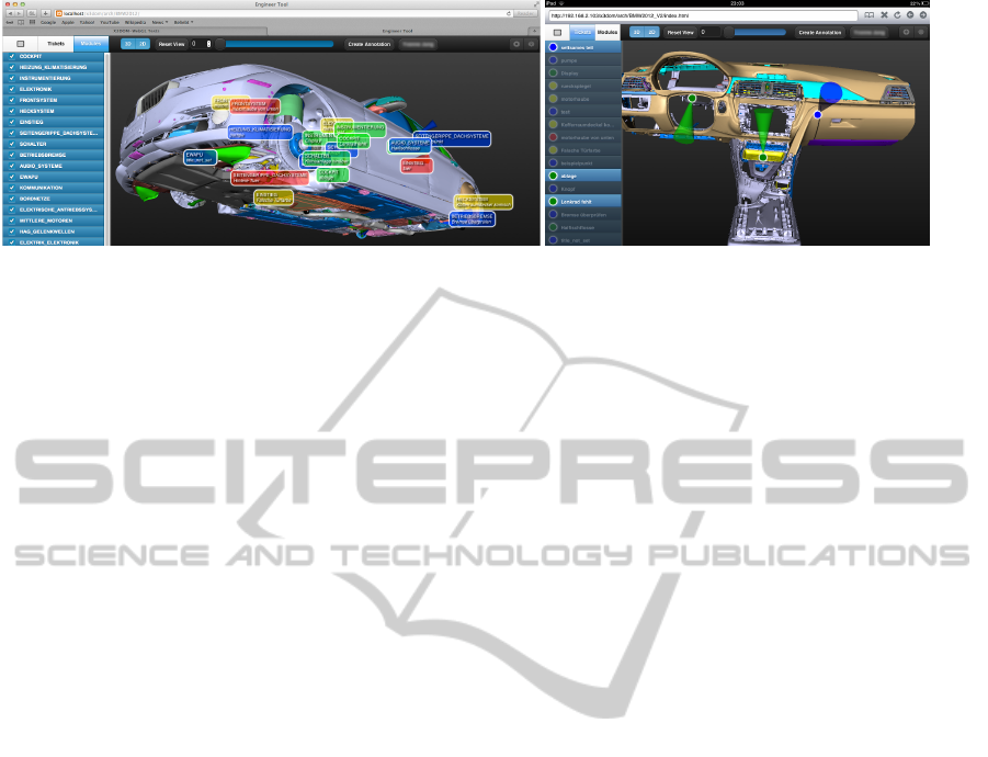
Figure 1: A 91M triangles CAD model of a car consisting of several base modules with 2D and 3D annotation markers,
rendered in a common Web Browser at real-time frame rates. Left: Using a desktop PC. Right: Using an iPad 2.
of APIs for hardware-accelerated rendering. WebGL
(Marrin, 2012), based on OpenGL ES 2.0, is already
supported by most of the major Browsers.
Additionally, the great advantage of a web-based
3D visualization is the ability to run it on a wide range
of different platforms without the need for native so-
lutions or plugins, why existing Web standards and
browser technologies should be preferred (Behr et al.,
2010). For being able to really use and smoothly com-
bine Web technologies, declarative 3D approaches
such as XML3D (Sons et al., 2010) or X3DOM (Behr
et al., 2010) are therefore embedding 3D content di-
rectly into HTML documents. This is currently done
using a so-called “polyfill layer”: the aim of such
approaches is to mimic native web browser support
for declarative 3D contents, as there is no declarative
3D Web standard yet. However, such a standard is
being actively developed (W3C Community Group,
2012). Nevertheless, one important aspect when us-
ing declarative 3D approaches for large and medium-
scale model visualization is that unstructured vertex
data should be separated from the structured scene
information by storing vertex data in external binary
containers outside the DOM (Behr et al., 2012).
Picking of 3D data has been extensively studied,
with the “Virtual Pointer” (Poupyrev et al., 1998) be-
ing one of the most popular metaphors for 3D inter-
action. Extensive research has been performed to im-
prove this basic technique, e.g. towards better us-
ability and performance through the use of an ob-
ject buffer in screen space implemented with stan-
dard OpenGL (Elmqvist and Fekete, 2008). Pick-
ing attributes of vertex data within a browser-based
setup using WebGL has been discussed in (Behr et al.,
2010; Blume et al., 2011). The latter uses a method
that spreads a 32 bit object ID over the 4 RGBA com-
ponents to overcome several limitations of WebGL
like missing buffer accessors. However, this comes
at the cost of not storing any object position informa-
tion inside the picking buffer. Independent from such
picking buffers, a 16-bit signed number format that
generalizes existing 8-bit formats using RGBA8 tex-
tures was presented in (Strzodka, 2002).
3 AN EFFICIENT VERTEX DATA
REPRESENTATION
Using declarative 3D approaches for the rendering of
large models, it is crucial to externalize vertex data
from the HTML document by using binary containers
(Behr et al., 2012). Attribute data can be concurrently
fetched by the Browser via Ajax calls or image down-
loads and is ideally “as is” transferred directly to GPU
memory for rendering. Such a straightforward ap-
proach significantly reduces the memory and process-
ing overhead, which is of high importance on mobile
devices with limited CPU power. Within this section,
we demonstrate how a compact vertex data represen-
tation for efficient visualization of large models inside
a web-based environment can be implemented.
3.1 Large Data Partitioning and Paging
Since WebGL only supports 16-bit indices, indexed
rendering only allows addressing a maximum of 64K
vertices per draw call (or, to be precise, 2
16
= 65, 536
vertices). Larger meshes thus have to be cut into sev-
eral patches, each containing 64K vertices or less.
We have currently implemented two methods for pre-
processing such meshes: a simple KD tree as well
as a vertex-cache-based approach. Both methods first
merge all meshes with the same material (i.e., color
and texture) into one big, flattened mesh.
The KD tree method (Wald and Havran, 2006)
splits the mesh recursively into two parts by sorting
each triangle either left or right of an axis-aligned
splitting plane. The splitting plane is chosen in such a
way that both parts contain nearly the same amount of
triangles. If one mesh part has fewer triangles than a
given threshold, the function stops. The result is that,
using the right threshold, every generated patch of the
mesh has less than 64K vertices. The other method
IVAPP2013-InternationalConferenceonInformationVisualizationTheoryandApplications
602
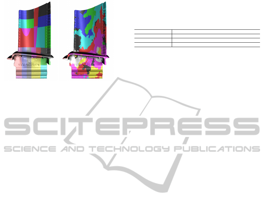
Figure 2: Partitioning of a 883K vertices turbine blade
model for rendering with WebGL. Left: Kd-tree-based ap-
proach, 32 patches. Right: Vertex cache optimization ap-
proach, using the minimum of 14 patches.
is based on a vertex cache optimization algorithm
(Forsyth, 2006). Simply put, the method combines
local clusters of triangles who share a lot of vertices
into one mesh. The function adds triangles one by
one and the vertices of the added triangle into a vertex
cache. Other triangles with vertices in the cache are
likely to be added next. During this process, a mesh
patch is considered to be complete if the amount of
shared vertices has reached the threshold of 64K. The
result is the minimum amount of patches with 16 bit
indices, generated from one far larger mesh. Figure 2
shows a comparison of results for both methods.
However, depending on the size of the model and
the memory capacity of the target device, another
problem has to be solved: the complete vertex data
might be too large to fit into GPU memory at all. We
thus use a fixed limit for the number of patches that
are drawn simultaneously. This limit is chosen with
respect to the target platform. In addition, each patch
is assigned a time stamp that stores the last time the
patch was rendered. If the time stamp indicates that
a patch has not been rendered for a duration greater
than a fixed threshold, the patch is evicted from mem-
ory. This corresponds to a very basic Least Recently
Used (LRU) strategy, as it is used for common large
model visualization approaches – compare e.g. (Brud-
erlin et al., 2007; Cignoni et al., 2004).
3.2 Compact Vertex Data Encoding
Visualizing large meshes as for instance required in
the scientific visualization or CAD domain, where
typical 3D models can have 50 - 100 million trian-
gles and even much more, the proposed techniques
have to be improved to minimize the numbers of bytes
per primitive (triangle or point) even further, with the
primary aim to significantly reduce the correspond-
ing GPU memory footprints. Like many other authors
Table 1: Average frame rates on MacBook Pro notebook
with ATI card and iPad for the 1,084,724 triangles Buddha
with vertex positions and normals. Both rightmost columns
compare the built-in sine computation with a Taylor series
approximation (right) for converting the spherical normals.
Byte encoding ~p +~n 3 · 2 + 3 · 1 4 · 2 + 4 · 1 3 · 2 + 2 · 1 3 · 2 + 2 · 1
dim(~n) & decoding 3d, w/o 3d, w/o 2d, sine 2d, approx.
AMD Radeon 6770M 1 fps 60 fps 59 fps 59 fps
iPad 2/ PowerVR 6 fps 26 fps 14 fps 21 fps
of common compact mesh formats, we found integer
coordinates with much less than 32 bit precision suf-
ficient; for a recent work see (Maglo et al., 2012).
While related work considered precisions of 12 bits
or even 10 bits sufficient to encode vertex positions
without a loss of visual quality, we are always using
16 bits. The reason is that the GPU will accept data in
32-, 16- or 8-bit precision, so we would have to pad 12
bit data to 16 bit anyway. We want to avoid such a step
on the client to save the CPU overhead. Therefore,
vertex positions are always encoded more precisely
with 16 bits, while for vertex colors and normals even
8 bit are sufficient. This not only drastically reduces
the file sizes of the externalized vertex attributes, but
it also does not require any decoding process on the
CPU, which is crucial on mobile devices.
The vertex positions, given as 16 bit integer val-
ues, are always encoded and decoded with respect to
the bounding box of the corresponding patch of the
model, though it is worth noting that per-patch bound-
ing volumes can introduce cracks at patch boundaries
due to precision errors. After that, the decoding on the
client side can be efficiently performed inside a ver-
tex shader: each integer coordinate is converted into
a normalized float value in [−1,1] by dividing by half
of the maximum short int value. The result is then
multiplied by the size of the corresponding bounding
box and translated to the bounding box’ center.
To further decrease the amount of loaded data, we
encode the vertex normal into the fourth component
w of the 16 bit vertex position, which would other-
wise remain unused due to the requirement that on
many GPUs, such as ATI or PowerVR, the vertex data
even in interleaved representation needs to be 32-bit-
aligned (Apple, 2011). Table 1 shows a comparison
for non-aligned (first column) vs. aligned buffer data
(other columns). Therefore, using xyz coordinates at
16 bit precision usually would require the use of an
extra padding component w for alignment.
Thus, to obtain a meaningful value of w for a
given vertex, we first convert the 3D normal vector
(n
x
,n
y
,n
z
) into 2D spherical coordinates (θ,φ), which
we then map to the 8 bit unsigned char range [0,255].
Several authors of compact mesh compression for-
mats (cf. e.g. (Hoppe, 1998)) have already proposed
this method as it has no visible impact in common
rendering setups, as long as normals are simply used
FastandEfficientVertexDataRepresentationsfortheWeb
603
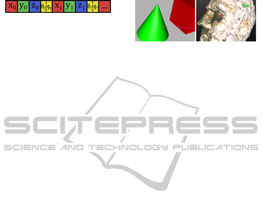
Figure 3: Compact vertex data storage in blocks of 16 bits.
to encode surface directions. Both of the 8 bit spher-
ical coordinates are then converted into one 16 bit
value w = 256 · θ + φ arithmetically to avoid endian-
ness issues. Note that the multiplication corresponds
to an 8 bit binary left-shift, which moves the θ com-
ponent to the upper byte of w, while the φ component
remains in the lower byte respectively (Figure 3).
For presentation, the converted vertex buffers are
loaded to the GPU using the standard WebGL API
and then decoded in a special vertex shader. First, the
encoded low and high byte of pos.w need to be re-
trieved. Using programming languages like C/C++,
this could be easily done using bit shifting and a bi-
nary AND. However, in our case the solution is a
bit tricky since bit operations are not possible in the
WebGL profile of GLSL. Moreover, w will be given
in floating-point precision inside the shader. Thus, the
following vertex shader code is used for decoding:
vec2 nor = vec2(pos.w / 256.0);
nor.x = floor(nor.x) / 255.0;
nor.y = fract(nor.y) * (256.0 / 255.0);
vec2 thetaPhi = PI*vec2(nor.x, nor.y*2.0-1.0);
First, w gets shifted eight bits to the right through
dividing by 256. This leads to the higher byte of w
being represented as the integer part, while the lower
byte is represented as the fractional part. Those two
components are then obtained by using the GLSL’s
built-in functions that isolate the integer part (floor)
and fractional part (fract) respectively. After this,
both values are mapped from their integer representa-
tion to the normalized floating point range [0,1] and
finally to the original range of θ and φ.
To convert the spherical values back to a vector
(n
x
,n
y
,n
z
), we make use of the well-known fact that
cos(x) = sin(x +π/2). Exploiting the SIMD GPU ar-
chitecture, we can calculate the sine and cosine of θ
and φ in only one single shader instruction as shown
next. The required values for converting (θ,φ) back
to (n
x
,n
y
,n
z
) are now contained in the resulting vec4.
vec4 v = vec4(thetaPhi, thetaPhi + PI_HALF);
vec4 sinCosThetaPhi = sin(v);
Although this is very fast on desktop GPUs, on
mobile graphics chips like the PowerVR used in Ap-
ple’s iPad even a single sine operation is still rather
expensive. Therefore, we further optimized this code
for mobile environments by replacing the sine opera-
tion with a cheaper Taylor series approximation (see
Table 1, right). Nevertheless, this method needs at
least five terms to avoid unpleasant shading artifacts
due to a poor function approximation.
Figure 4: Picked surface normal estimation. Left: A simple
demonstration. Right: Example from the cultural heritage
domain, with an unoriented annotation marker (green) and
an oriented, cylindrical one (red), auto-oriented through our
normal estimation method. Note how the oriented marker
helps to specify the exact location on the surface.
4 FAST AND PRECISE PICKING
Gaining insight from visualized 3D data requires sev-
eral interaction possibilities including interacting di-
rectly with the data via UI events, where picking tech-
niques can be used for a detailed inspection. In the
following, we show how to realize precise picking ef-
ficiently inside a web-based rendering system.
4.1 Picking Buffers
Picking objects is often implemented via ray intersect
by traversing the scene-graph, checking the bound-
ing boxes and testing candidate triangles, which un-
fortunately is not fast enough with JavaScript in a
Web Browser. Thus, a render-buffer-based approach
instead of standard intersection tests should be pre-
ferred. However, the old school OpenGL selection
and feedback functionality (McReynolds and Blythe,
2005) is not available in WebGL. Therefore, e.g. in
(Behr et al., 2010) the picking buffer is implemented
by first rendering the scene into an RGBA texture at-
tached to a framebuffer object (FBO): the normalized
world coordinates are encoded in the RGB channels,
and the alpha channel contains the object ID referenc-
ing the rendered object. Occlusions are automatically
handled by the depth buffer. By retrieving the val-
ues located under the mouse pointer via the WebGL
function readPixels(), the ID of the picked object
is obtained with 8 bits of precision.
4.2 Distance-based Picking
Due to the mentioned 8-bit RGBA representation, the
main problem of the picking buffer method is miss-
ing precision for the picked positions and the fact
that only 255 objects could be identified within one
picking pass. For higher precision or more identifi-
able objects several picking buffers and render passes
would be necessary, which would lead to a signifi-
cant drop of the frame-rate during rendering. While
IVAPP2013-InternationalConferenceonInformationVisualizationTheoryandApplications
604

there exists a WebGL extension for floating-point-
precision textures, this feature is not yet available
for mobile systems like the iPad or the new Nexus
7 tablet, which supports WebGL with Opera and Fire-
fox mobile. Even worse, floats can only be used on
the GPU (e.g., depth maps for shadow calculations),
since the only allowed format and type combination
for readPixels() in WebGL is still RGBA and UN-
SIGNED BYTE (Marrin, 2012, Section 5.14.12).
Hence, we propose a new approach that supports
64K different objects (to be exact: 2
16
− 1, as 0 rep-
resents the absence of objects). Furthermore, within
the same pass, we obtain a high-precision 16-bit pick
position, as well as the normal at the picked position
(both in world space) for all mouse or touch events.
Despite the improved precision, we still employ a
single-pass render-buffer-based approach with a stan-
dard 8-bit RGBA buffer due to WebGL’s FBO limita-
tions.
Instead of rendering the normalized world posi-
tion directly into an FBO-texture’s 8-bit RGB chan-
nels and the internal object ID into the 8-bit alpha
channel, we just render the distance from the picked
point to the camera position into the RG channels.
This distance value is computed and encoded as a 16-
bit value inside the special fragment shader used by
the picking pass. Having the distance d between the
camera and the picked position provides enough in-
formation to calculate the full 3D position. This is
simply achieved by computing the viewing ray from
the eye through the picked 2D pixel position (x,y).
The corresponding object’s ID is rendered accord-
ingly into the texture’s BA channels, also using 16
bits. After having rendered the picking pass, the 16-
bit ID and picking distance are decoded on the CPU
in JavaScript, analogously to how the normal values
are decoded from a single 16-bit value (Section 3.2).
However, flattening the original graph as outlined in
Section 3.1 poses another problem, since the original
graph structure is lost. To alleviate this issue, a nu-
meric identifier denoting the original geometry is en-
coded in an additional vertex attribute during prepro-
cessing along with a name-id map exported as JSON
file. In the picking pass we then simply use the per-
vertex ID instead of the object ID, while the original
object name, including the mapping between flattened
and original meshes, is derived from the JSON object.
4.3 Picked Normal Estimation
Instead of just reading back one single 8-bit RGBA
value at the picked pixel position (x,y), we read back
a small 2 × 2 window, which enables us to directly
compute the object’s normal. We do so by taking
the cross product of the decoded world space posi-
tion above the pick point (x,y − t) and to the right
(x + t,y) of it. Since for performance optimizations
we render the picking buffer with only half of the ren-
der buffer size, the neighbor pixels are accessed using
an accordingly scaled pixel offset t. Having the nor-
mal data at the picked position at hand is especially
essential for more advanced forms of interaction. For
example, annotation markers that can be added by the
user, as shown in Figure 1, can be oriented and posi-
tioned correctly this way. Figure 4 shows two other
examples using our normal estimation method.
Table 2: Memory consumption for several test models, en-
coded as X3D binary and with our compact binary format.
In all cases, the vertex data contains positions and normals.
Model #Triangles X3DB Our format
Buddha 1,084,724 24.97 MB 7.21 MB
Blade 1,765,388 40.90 MB 11.46 MB
Car 95,924,885 1,621.99 MB 498.94 MB
5 DISCUSSION AND RESULTS
We have provided hints that are useful for the effi-
cient and meaningful visualization of even complex
3D models inside common Web browsers, running on
different platforms. First, we have shown that large
models with more than 2
16
vertices need to be split
into several patches for rendering with WebGL. To
construct those patches, we have compared two meth-
ods: A kd-tree-based approach as well as an approach
based on vertex cache optimization.
The kd tree method has the advantage that each
patch has a tight bounding box, which is almost not
overlapping at all with the bounding boxes of other
patches. This is especially useful for view frus-
tum culling. Although the method is easy to imple-
ment, the drawback is that the amount of vertices per
patch and draw call is far from optimal. In contrast,
the vertex-cache-based approach always constructs
patches with nearly the optimal amount of 64K ver-
tices. Along with the improved GPU vertex cache co-
herency, the smaller number of draw calls ensures an
optimal rendering performance. The only drawback
here is that the bounding boxes of the patches can be-
come larger than for the kd-tree-based approach (see
Figure 2, right). However, this depends on the mesh
and the number of shared vertices.
Our implementation is able to render the 91M tri-
angles model shown in Figure 1 in a standard web
browser. Table 2 shows a comparison of file sizes for
several models, stored in the X3D binary format x3db
(Web3D Consortium, 2011) and with our compact bi-
nary encoding. As can be seen, we need less than 30%
of disk space compared to x3db. Moreover, the model
FastandEfficientVertexDataRepresentationsfortheWeb
605

can be loaded much faster, and even in parallel, as we
can exploit the browser’s capability to download sev-
eral patches of the mesh at a time. In contrast to other
web-based formats like X3D, the data can directly be
transferred “as is” to the GPU, without any further
CPU-based processing inside the client’s JavaScript
layer. While our vertex data format is more compact
than previous ones, the client’s GPU memory must
still be able to hold all data that is currently rendered.
Otherwise, constant paging of data packages totally
breaks performance. Luckily, for typical large mod-
els like this car, it mostly makes no sense to display
all its components simultaneously: e.g. one will ei-
ther display the car’s body or the interior of the motor
compartment, but never both at the same time.
The identification of one out of up to 64K ob-
jects during picking is made possible through our im-
proved single-pass picking buffer algorithm, provid-
ing 16 bits of precision for picked vertex attributes.
All proposed model processing, rendering, and inter-
action methods have been integrated into the open-
source framework X3DOM (Behr et al., 2010; Behr
et al., 2012) and the publicly available Mixed Reality
framework instantReality (FhG, 2012).
6 CONCLUSIONS
Within this paper, we have discussed some important
aspects of our approach towards fast and precise vi-
sualization of – and interaction with – 3D model data
inside a Web Browser. Our methods are straightfor-
ward to implement, easy to use, and enable visual-
izations of various kinds of input data, ranging from
scientific visualization to highly complex CAD mod-
els.
For the future, we would like to investigate the
possibility of using a progressive loading mechanism
that does not introduce too much CPU processing
overhead on the client side. This could lead to a sig-
nificantly improved user experience. Visualizing ex-
tremely large models with many millions of polygons
also requires more sophisticated techniques for out-
of-core rendering. The integration of such methods
into browser-based visualizations, especially on mo-
bile devices, is thus another interesting challenge.
REFERENCES
Apple (2011). OpenGL ES Programming Guide for iOS.
Ch. Best Practices for Working with Vertex Data,
pages 65–77.
Behr, J., Jung, Y., Franke, T., and Sturm, T. (2012). Using
images and explicit binary container for efficient and
incremental delivery of declarative 3d scenes on the
web. In Web3D 2012, pages 17–25, New York, USA.
ACM Press.
Behr, J., Jung, Y., Keil, J., Drevensek, T., Eschler, P.,
Z
¨
ollner, M., and Fellner, D. (2010). A scalable ar-
chitecture for the HTML5/ X3D integration model
X3DOM. In Web3D 2010, pages 185–193, New York,
U.S.A. ACM.
Blume, A., Chun, W., Kogan, D., Kokkevis, V., Weber,
N., Petterson, R. W., and Zeiger, R. (2011). Google
body: 3d human anatomy in the browser. In ACM
SIGGRAPH 2011 Talks, page 19, New York, USA.
Bruderlin, B., Heyer, M., and Pfutzner, S. (2007). Inter-
views3d: A platform for interactive handling of mas-
sive data sets. Computer Graphics and Applications,
IEEE, 27(6):48 –59.
B
¨
urger, R. and Hauser, H. (2007). Visualization of multi-
variate scientific data. In Eurographics 2007 State of
the Art Reports, pages 117–134.
Cignoni, P., Ganovelli, F., Gobbetti, E., Marton, F., Pon-
chio, F., and Scopigno, R. (2004). Adaptive tetra-
puzzles: efficient out-of-core construction and visual-
ization of gigantic multiresolution polygonal models.
In ACM SIGGRAPH 2004 Papers, SIGGRAPH ’04,
pages 796–803, New York, NY, USA. ACM.
Elmqvist, N. and Fekete, J.-D. (2008). Semantic pointing
for object picking in complex 3d environments. In
Proc. Graphics Interface 2008, pages 243–250.
FhG (2012). Instant Reality. www.instantreality.org.
Forsyth, T. (2006). Linear-speed vertex cache optimisation.
http://home.comcast.net/
˜
tom forsyth/papers/fast vert
cache opt.html/.
Hoppe, H. (1998). Efficient implementation of progressive
meshes. Computers & Graphics, 22:27–36.
Maglo, A., Courbet, C., Alliez, P., and Hudelot, C.
(2012). Progressive compression of manifold polygon
meshes. Computers & Graphics, 36(5):349–359.
Marrin, C. (2012). WebGL specification.
https://www.khronos.org/registry/webgl/specs/latest/.
McReynolds, T. and Blythe, D. (2005). Advanced Graphics
Programming Using OpenGL. Morgan Kaufmann.
Poupyrev, I., Weghorst, S., Billinghurst, M., and Ichikawa,
T. (1998). Egocentric object manipulation in vir-
tual environments: Empirical evaluation of interaction
techniques.
Sons, K., Klein, F., Rubinstein, D., Byelozyorov, S., and
Slusallek, P. (2010). Xml3d: interactive 3d graphics
for the web. In Web3D 2010, pages 175–184, New
York, NY, USA. ACM.
Strzodka, R. (2002). Virtual 16 bit precise operations on
rgba8 textures. In VMV 2002, pages 171–178. Aka.
W3C Community Group (2012). Declara-
tive 3D for the Web Architecture. http://
www.w3.org/community/declarative3d/.
Wald, I. and Havran, V. (2006). On building fast kd-trees for
ray tracing, and on doing that in o(n log n). In Proc.
IEEE Symp. Interactive Ray Tracing, pages 61–70.
Web3D Consortium (2011). Extensible 3d (X3D).
http://www.web3d.org/x3d/specifications/.
IVAPP2013-InternationalConferenceonInformationVisualizationTheoryandApplications
606
