
Embedded System Architecture for Mobile Augmented Reality
Sailor Assistance Case Study
Jean-Philippe Diguet
1
, Neil Bergmann
2
and Jean-Christophe Morg
`
ere
1
1
Lab-STICC, CNRS, Universit
´
e de Bretagne Sud / UEB, Lorient, France
2
School of Info. Tech. and Elec. Eng., The University of Queensland, Brisbane, Australia
Keywords:
Embedded System Design, Augmented Reality, Hardware/Software Codesign, Reconfigurable Computing.
Abstract:
With upcoming see-through displays new kinds of applications of Augmented Reality are emerging. How-
ever this also raises questions about the design of associated embedded systems that must be lightweight and
handle object positioning, heterogeneous sensors, wireless communications as well as graphic computation.
This paper studies the specific case of a promising Mobile AR processor, which is different from usual graph-
ics applications. A complete architecture is described, designed and prototyped on FPGA. It includes hard-
ware/software partitioning based on the analysis of application requirements. The specification of an original
and flexible coprocessor is detailed. Choices as well as optimizations of algorithms are also described. Imple-
mentation results and performance evaluation show the relevancy of the proposed approach and demonstrate
a new kind of architecture focused on object processing and optimized for the AR domain.
1 INTRODUCTION
Recent breakthroughs in the domain of wearable dis-
plays indicate that Augmented Reality (AR) systems
will bring new applications in the near future. How-
ever, this also implies an emerging challenge regard-
ing the design of low-cost, low-power systems to be
embedded in see-through glasses. Indeed, most of the
research work in related conferences (e.g. ISMAR) ,
doesnt focus on embedded system design but on spe-
cific AR issues such as reality overlay or virtual ob-
ject handling. The objectives of this work are firstly
an in-depth study of application requirements for spe-
cific positioning and drawing of 3D objects on a see-
though screen, according to the user vision of field.
Secondly this is the design of suitable hardware ar-
chitecture solutions based on upcoming FPGA
1
tech-
nologies. More precisely we address a problem that
can be defined with the two following questions:
1) How to position and draw a list of relatively sim-
ple 3D objects composed of a set of polygons, which
are defined by vertices with 3D coordinates on a see-
through head mounted displays (HMD)?
2) How to efficiently integrate this solution on an
FPGA-based reconfigurable architecture, while con-
sidering flexibility for various application and com-
plexity contexts?
1
Field Programmable Gate Arrays
The paper is organized as follows. In Section 2,
we present our motivations for this research field and
the target applications we consider. Section 3 gives an
overview of the relevant technologies for AR, includ-
ing architectures. Section 4 describes the main steps
of our original approach. Our solution is based on the
adaptation of previous positioning solutions to the ap-
plication context, on algorithmic transformations and
on a new architectural solution for object drawing. In
Section 5, we present our hardware/software architec-
ture. Our solution is flexible and optimized according
to AR applications and algorithm choices. In Section
6, implementation results and performances estima-
tions are given and discussed. Finally we conclude
and draw some overall insights.
2 CASE OF SAILOR ASSISTANCE
2.1 Application Context
AR by itself is not a new topic but many challenges
remain unsolved, especially in mobile and outdoor
contexts where field markers arent applicable and
video-assisted model-based tracking is usually inef-
ficient in real-life luminosity conditions. The pro-
posed application set is based on the following ob-
servations. First, designers already have at their dis-
16
Diguet J., Bergmann N. and Morgère J..
Embedded System Architecture for Mobile Augmented Reality - Sailor Assistance Case Study.
DOI: 10.5220/0004311700160025
In Proceedings of the 3rd International Conference on Pervasive Embedded Computing and Communication Systems (PECCS-2013), pages 16-25
ISBN: 978-989-8565-43-3
Copyright
c
2013 SCITEPRESS (Science and Technology Publications, Lda.)

a) Coast view – sunny weather
Buoy 700 m Semaphore
800 m
Chapel
950 m
Lighthouse
900 m
Heel
Trim
Heading
3m/s
b) Same Coast – foggy weather
c) Augmented reality with Seamarks and Indications
GPS
S
o
S
u
S
b
Boat Data
Available Data
AIS system
Seamarks
Streams
Figure 1: Sailor Assistance AR case study.
posal an ever-increasing amount of recorded and clas-
sified data of geolocalisation. Second, considering
see-though glasses, these data can be added to a users
field of vision to provide mobile outdoor AR applica-
tions. Third, 3D objects can be computed to fit with
the landscape seen by the user if the user attitude can
be obtained with appropriate sensors. Fourth, except
for specific applications like architectural designs, the
constraint of overlay accuracy is reduced for distant
objects and no camera is required for the pose esti-
mation. In this context many applications can be de-
signed to improve security and orientation decisions,
in different hands-free and low footprint devices. We
consider the particular but complicated case study of
sailor assistance from which can be derived various
requirements for a generic system. On a boat, un-
derstanding of the position is vital when approaching
sensitive environments such as coasts, open sea reefs
or harbour navigation channels. These situations are
true for small sailing or motorboats but also on large
vessels, where the navigation crew is limited with re-
spect to boat sizes. In these kinds of long ships, it is
also recommended to combine visual checking, based
on real environment observations, and instrument pi-
loting. Current methods consist of going back and
forth between map analysis and visual observations.
Matching map indications with a real environment
can be tricky and error-prone, and it also represents
a loss of time that can be precious in case of emer-
gency. Finally, matching can be simply impossible
when the visibility is very bad (see Fig.1). This is a
relevant case study since a ship is a very unstable sys-
tem. All the continuing motions have various param-
eters depending on boat speed, user moves and ocean
oscillations. Swell periods can vary between 0.05Hz
and 0.1Hz. But this is also a domain where a lot of
data are available. The first category is composed of
static seamarks objects, the second one is dynamic but
can be estimated, for instance the ocean streams. The
third one is related to the positions, heading and ID
of boats or any maritime objects in the surroundings
provided by the AIS system. All these data can be
added to the user fields of vision according to po-
sition and attitude estimations. Then we have boat-
positioning data, which include GPS measurements,
speed, trim, heel, and heading. All these data can be
obtained through a wireless network that doesnt re-
quire high bandwidth capacities. But while these data
are useful they are not sufficient since it is necessary
to know the user attitude defined with head angular
positions. These data have to be provided by embed-
ded sensors that must be integral with the glasses. Re-
dundancy between boat and user data can also be use-
fully combined to improve accuracy. For instance the
on-glasses accelerometers can be combined with the
ship GPS to estimate local moves on a long vessel.
2.2 Related Optimizations & Challenges
Specific optimizations can be applied with respect to
general-purpose 3D graphics. We can point out three
of them. i) Object distance means relaxed accuracy
constraint: orientation information in outdoor appli-
cations is useful for distant objects. So one can relax
the constraint of accuracy since the size of the ob-
ject is decreasing with distance. It also means that a
camera isnt required and neither are complex object
tracking methods, which can be inefficient outdoors
because of their sensitivity of luminosity changes. ii)
No background and a limited number of objects: the
background is the real world that can be seen with
see through glasses, moreover ergonomics and obvi-
ous usefulness, impose that a limited number of ob-
jects can be drawn at the same time. iii) Static or slow
objects: most useful orientation objects are static or
move slowly if they are far away. All the previous fea-
tures provide a rationale for a simplified implementa-
tion of 3D graphics that may be usefully exploited to
optimize the design of the embedded system.
3 STATE OF THE ART
3.1 MEMS Sensors
The first breakthrough occurred in the domain of
sensors for position, speed, acceleration and attitude
(yaw, pitch, roll) measurements. For a long time,
the size, and cost of such devices have limited their
use to navigation instruments in aircrafts and satel-
lites. However MEMS
2
technologies are now provid-
2
Micro Electro-Mechanical Systems
EmbeddedSystemArchitectureforMobileAugmentedReality-SailorAssistanceCaseStudy
17

ing integrated and low cost Inertial Measurement Unit
(IMU) solutions (Li et al., 2008; Nasiri, 2010) that
make possible the design of mobile consumer sys-
tems. The most widespread solution is based on the
association of two kinds of MEMS devices: a 3-axis
accelerometer sensor and a 3-axis magnetometer sen-
sor. The combination of these sensors can provide the
estimation of a body translations and attitude, which
means 3 axes inclinations and so compass capabili-
ties. More recently gyroscopes, that return angular
velocities, have also been proposed in integrated ver-
sions. Invensense
3
has unveiled in 2010 an IMU in-
cluding a 3-axis integrated gyroscope (angular speed)
combined with a 3-axis accelerometer. In September
2011 ST presented the iNemo
4
engine that includes 3-
axis linear accelerometers, 3-axis angular speed mea-
sures, a magnetometer (heading) and a barometer (al-
titude). Like the Invensense solution, the whole de-
vice uses a 32 bit processor to run motion estimation
algorithms. However it will be shown in Section 6
that a gyroscope is really not needed in our context,
moreover we will see that a softcore synthesized on a
FPGA can run motion estimation.
3.2 HMD Displays
The second kind of technology that opens new hori-
zons to AR applications comes from the domain of
HMD. New see-through glasses (see Fig.2), will soon
be available. Some prototypes already exist and
should soon be commercially available. Companies
like Vuzix, Optinvent, Laster or Lumus have devel-
oped prototypes or already commercialize some prod-
ucts with important limitations. Google is also an-
nouncing glasses, which in reality seem to be a Head
Mounted Display. HMDs are still very new, but this
type of device paves the way to make future AR real-
ity applications available at a reasonable cost. More-
over in 2011, the first prototype of a single-pixel lens
has been demonstrated (Lingley et al., 2011). This
now raises the question of integration of the embed-
ded system since current approaches are based on
wired connections with smart phones or laptops that
provide data to this new display.
3.3 Embedded System Architectures
Miniaturization and power consumption are impor-
tant issues for mobile AR systems, which mainly re-
quire computation resources for object positioning
and for drawing, and also control capacities for data
3
www.invensense.com/
4
www.st.com/internet/evalboard/product/ 250367.jsp
acquisition from sensors with standard communica-
tion protocols. Different solutions may be considered
for the implementation of such applications. The first
solutions rely on advanced embedded multiprocessor
architectures based on a CPU enhanced with a GPU.
They are typically based on cortex ARM cores or In-
tel Atoms with specialized Graphics and Video co-
processors. The advantage of such architectures is
the availability of software development frameworks.
While high-resolution video games, video and image
processing for object identification and online reality
overlay would justify such impressive processing re-
sources, for the types of AR applications we are tar-
geting there is no need for cameras and complex pose
computation including image processing, and so such
CPU-GPU solutions would be overkill. Another pos-
sible solution is provided by reconfigurable architec-
tures that enable specifically optimized and low fre-
quency designs. These rely on Hardware / Software
design methodologies and recent high-performance
FPGAs. These FPGAs are often power-hungry how-
ever the roadmap of FPGAs is clearly focused on this
power issue with the aim to address the embedded
system market. The hybrid ARM/FPGA Zynq ar-
chitecture, released by Xilinx in 2012, clearly opens
new perspectives. On-chip memory capacity is also
a key issue where significant progresses have been
made. For example, the Artix Xilinx low power, low
cost family embeds up to 12Mbits of block RAMs.
Regarding GPUs on FPGAs, Xylon has added a 3D
graphics module to the Logibrick library. The ar-
chitecture relies on a 3 stage pipeline: i) Geome-
try/Rasterization based on Micro-Blaze Xilinx soft-
core enhanced with a coprocessor able to compute
coarse grain mathematical instructions; ii) Renderer:
pixel color, texture, occlusion implemented as an ac-
celerator connected to the PLB bus and iii) full ren-
dered 3-D scene anti-aliasing also implemented as
master hardware module. This solution is a simpli-
fied version of the usual graphics pipeline and is de-
signed for general purpose Open-GL-ES applications.
It shows that low frequency dedicated architectures
can be designed for this purpose. In (Kingyens and
Steffan, 2011) the authors present a GPU-inspired and
multi-threaded softcore architecture, which is pro-
grammable with the NVIDIA Cg language. The aim
is to simplify the use of FPGA-based acceleration
boards for High Performance Computing. Our ap-
proach is different, strongly dedicated to embedded
systems and AR applications with a high focus on
data locality optimization for minimizing data trans-
fers. From a general point of view, 3D graphics is a
very complex and greedy application field but if we
consider the most promising AR applications, we ob-
PECCS2013-InternationalConferenceonPervasiveandEmbeddedComputingandCommunicationSystems
18
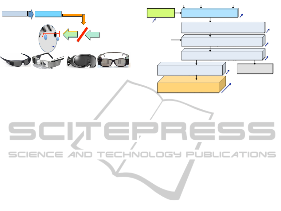
Optical See-Through HMD
Pico Projector
Computer
Virtual 3D objects
Real World
Optical Combiner /
Element
Lumus
Optinvent
Laster
Vuzix
Figure 2: Upcoming see-through glasses.
serve that optimizations and simplifications are possi-
ble and can lead to very efficient solutions. Moreover,
one can consider available soft cores that can run a
standard Linux OS to simplify sensor interfaces. Such
soft-cores have limited performance but can be en-
hanced with dedicated reconfigurable accelerators to
implement energy-efficient flexible architectures on
a single chip. As demonstrated in (Benkrid, 2010),
FPGA can overcome CPU and GPU with orders of
magnitude in terms of energy efficiency by allowing
fully dedicated architectures. Finally dynamic hard-
ware reconfiguration also provides opportunities to
adapt the architecture to the application context and
requirements. Our solution follows this approach.
3.4 Conclusions
AR research trends analysis shows that the five main
research topics over the last ten years are Tracking
techniques, Interaction techniques, AR applications,
Calibration and registration and Display techniques.
This state of the art is backed up by the first analysis
and optimization opportunities given in Section 2.2.
Significant progresses and research have been done
on how to apply AR in terms of techniques and al-
gorithms that are increasingly mature. AR has also
pushed emerging display and sensor technologies but
the question of integration has not been a major fo-
cus. People are more focused on the previously de-
tailed issues and consider implementation and archi-
tecture as a secondary problem. By considering algo-
rithms ready for our application domain our study is
focussed on application / architecture matching.
4 APPLICATION ALGORITHM
CHOICES & OPTIMIZATIONS
4.1 Solution Steps
In the following Sections we present the design
GPS
Accelerometer Magnetometer
In memory Local
object description
(Network => Update)
!!"#$%&'()*+,-+$-./)0($.'1)2$*-('3-+$4-*$$
'55$-./)0($6)*30)1$
!!"7$8,9:3+9$'+2$*)+2)*,+9$4-*$'55$-./)0($
6,1,.5)$;-5<9-+1$
!!"=$>,)?;-*($'+2$@)*1;)036)$4-*$$
'55$-./)0($6,1,.5)$;-5<9-+1$
!!"A$B'1()*,C'3-+$'+2$;,D)5$0-5-&*,+9$$
'55$-./)0($6,1,.5)$;-5<9-+1$
!!"E$F./)0($0';3-+$
2,1;5'<$
G"H'5,.*'3-+$
# Iterations
0) 1Hz a) 50Hz
b) 50Hz*#Vertices*#Object
c) 50Hz*3*#VisiblePolygons1
d) 50Hz*3*#VisiblePolygons2
e) 50Hz*#VisiblePolygons2 *
#AvgPixel_per_Polygon
e
a
a
b
c
d
0
!"@-1,3-+$'+2$IJ(&2)$)13K'3-+$
!!"L$M@N$"O$PHPQ$"O$PRS$
H--*2,+'()$1<1()K$(*'+14-*K'3-+1$
Figure 3: Global application flow.
choices to specify and implement the complete appli-
cation flow described in Fig.3. We address the three
following points: i) Object positioning according to
sensors and application context, ii) Object drawing,
iii) some optimisations that have been introduced ac-
cording to the application context.
4.2 User Attitude Modelling
In this domain the objective was to develop a robust
and gyro-free solution based on magnetometer, GPS
and accelerometer. There were two difficulties. The
first one was the state of the art that was mainly re-
lated to aircraft, automotive systems or AR applica-
tions with computer-based implementation including
gyroscopes and without great concerns about size and
power consumption issues (Zhu et al., 2007; Waegli
et al., 2007; Li et al., 2008). The second point is
related to the filtering and estimation problem, ac-
tually determining position, speed and attitude from
a set of noisy sensors is a non-linear problem that
can’t be solved with traditional Kalman filters. We’ve
studied various kinds of alternative solutions for non-
linear filters, which were based on EKF (extended
Kalman filter) (Kim et al., 2009), UKF (unscented
Kalman filter) (Shin and El-Sheimy, 2004) or UPF
(unscented particle filter) (Koo et al., 2009). Ac-
cording to the current project environment and con-
straints, it turned out that applying Wahbas method
could solve the question of the gyroscope. This tech-
nique has been applied in aeronautics and avionics do-
main in (Gebre-Egziabher et al., 2000) and considers
gravity and magnetic field as the two required non-
collinear vectors. It is based on the quaternion mod-
eling, which also offers interesting properties such as
the computation complexity for rotations, the stability
in presence of coding and rounding errors and the in-
herent robustness regarding the gimbal lock problem.
EmbeddedSystemArchitectureforMobileAugmentedReality-SailorAssistanceCaseStudy
19
The solution finally developed is based on a low com-
plexity 6-states EKF algorithm for speed and position
estimations. This EKF is loosely coupled with a low
frequency GPS and gets the body attitude data, as a
quaternion vector, from a 6-states KF algorithm that
implements Wahba’s method. The proposed EKF-
6 algorithm was previously applied in (Bijker and
Steyn, 2008) with gyroscope data that are removed in
the proposed version. Moreover the acceleration data
are combined with data from GPS after filtering. The
complete solution also relies on a robust method for
the auto calibration of the magnetometer (Guo et al.,
2008). It leads to a complex 14 states EKF algorithm,
however it is used only once at start time or with a
very low frequency if the environment is changing.
Note that the solution can easily be augmented with
new data. It means that if gyroscope data are avail-
able with reasonable cost and footprint, they can be
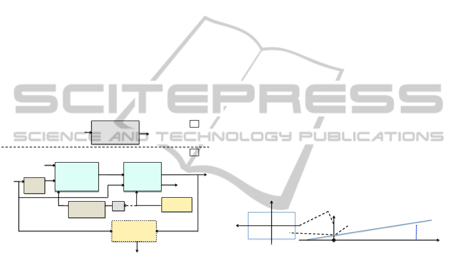
added to the model. The complete solution for posi-
tion and attitude estimation is described in Fig.4.
!"#$%&"'()*
(+*%(,-*.-./01**
234567*
!"#$%&'((
)*+,(
!-
*+.+,(
!"#$%&#'%$(")
*(+),-./0."12)
,-./0."12)
3456)
/01(
/0)(
8(,-*9:/;,0*<6=*
2.'1"'()**
345>*
?(.$'()*@A00,*
<B=**
2.'1"/0**
2345>*
122%3%4'5%&%4(
1-*+,(
(!-
*+.+,(
67"&%4$8'$(
9
-(
:(
;
(
0<(
=
>(
:(
='?8@'$(
A
(
:(
BC%%D(
E=B((
F?%4GA%H823%(I+J(
='?8@'$(%?@5"&%(
122K(/$&%#4"@'$(
=LA (
DGD&(
"M(
M8$%"4(122(
N'44%2@'$(IOJ(
!"#$%&'5%&%4(
)*+,(
=
-(
:(
Figure 4: Position and attitude estimation.
4.3 Virtual Object: Geometry Stage
The objective is to select only objects of interest in
the context of the user. The definition of interest is a
real question that can be discussed but which is out
of the scope of this paper. In this work we consider
third configurable filters but various rules could be in-
troduced. The first one is obvious; this is the position
in the user field of view. The second is the minimum
size of object after 2D projection. The third one is the
choice of accessible objects stored in the object mem-
ory. This selection is implemented in software and
can be configured according to confidentiality issues
or contextual search criterions. Hereafter, we summa-
rize the steps of the geometry stage.
4.3.1 From GPS to ENU Coordinates
Given the GPS coordinates, there are two successive
transformations to apply: the first one from GPS to
ECEF (Earth-Centered, Earth-Fixed) and then from
ECEF to ENU (East North Up).
4.3.2 Object Rotation based on User Attitude
The user attitude, namely the three angles that define
user head orientation, is modeled with the quaternion
formalism (q = q
0
+ q
1
.i + q
2
. j + q
3
.k). Then a rota-
tion (from V to V ) is applied to every point of every
visible object according to the following operation:
V = q.V.q
−1
where q
−1
= q
0
−q
1
.i−q
2
. j −q
3
.k (1)
4.3.3 In-viewing Frustum Test, 3D→2D
The objective of the 2D projection step is firstly the
selection of visible points and objects within the user
field of vision and secondly the computation of 2D
coordinates after a perspective projection. An object
is considered as visible if it is in the field of vision,
which is defined with horizontal and vertical angles
and if it has a size bigger than a minimum sphere,
which is defined by a ray R. The viewport operation
is based on these bounding values and requires, for
every point of all relevant objects, 4 multiplications
and 4 tests. Then the projection can be computed with
3 divisions per object and then 4 products for every
point of all visible objects.
x’
z’
R
Zmax
R
Xmax
x
o
o
z’
y’
A(3D)
A’: perspective
projection of A
View Plan
x’
A’(2D)
User coordinates [x’,y’,z’]
2D projection
Figure 5: From user 3D coordinates to 2D view plan.
4.4 Virtual Object Drawing
4.4.1 Visibility Tests
Before drawing any object, three tests are applied.
The first one has been described in the previous Sec-
tion. The second test addresses the sign of polygon
normal vectors. Considering opaque surfaces, if the
Y value Ny of the polygon normal vector in the user
coordinates system is negative, then the polygon isnt
visible. Based on vertices coordinates, this value is
computed for each polygon and requires 3 multiplica-
tions and 4 additions. The third test is the well-known
Z-buffer test (Y-buffer with our conventions), the aim
is to avoid drawing polygons, which are hidden by
some closer ones. It is based on an array A[i,j] that
stores the smaller Y value of the closer polygon point
located at the address (i,j), where i and j correspond
to the ith line and jth column of the display. The ras-
terization step computes the pixel coordinates of each
PECCS2013-InternationalConferenceonPervasiveandEmbeddedComputingandCommunicationSystems
20
point after the 2D projection (step (4) in Fig.3). This
test can be implemented with a dedicated module that
computes address and performs comparison and up-
date, details are given in Section 6.
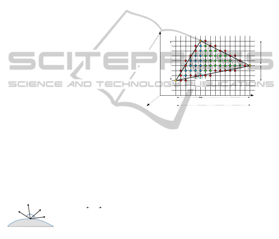
4.4.2 Light Modelling and Optimization
Models used are based on the barycentre method from
OpenGL-ES. The light model for each Vertex of the
triangle polygon is given in Fig. 6. Once the three
vertex lights are computed (L
1
, L
2
, L
3
), the barycentre
method can be applied to fill the triangle A,B,C and
compute each vertex light as follows:
L
c
(x,z) = A(x,z)L
1
c
+ B(x,z)L
2
c
+C(x,z)L
3
c
(2)
where: c = R,G, B, A(x,z) = F
23
(x,z)/F
23
(x
1
,z
1
);
B(x,z) = F
31
(x,z)/F
31
(x
2
,z
2
), C(x, z) =
F
12
(x,z)/F
12
(x
3
,z
3
) and F
i j
(x,z) = (z
i
− z
j
)x +
(x
j
− x
i
)z + x
i
.z
j
− x
j
z
i
The implementation of
this method has been optimized as follows: F
i j
can be computed only once for each triangle
and K
px
(c) and K
pz
(c) can be defined as unique
color increments on X and Z axis respectively:
K
px
(c) = L
1
(c)((z
2
− z
3
)/F
23
(x
1
,z
1
)) + L
2
(c)((z
3
−
z
1
)/F
31
(x
2
,z
2
)) + L
3
(c)((z
1
− z
2
)/F
12
(x
3
,z
3
))
K
pz
(c) = L
1
(c)((x
3
− x
2
)/F
23
(x
1
,z
1
)) + L
2
(c)((x
1
−
x
3
)/F
31
(x
2
,z
2
)) + L
3
(c)((x
2
− x
1
)/F
12
(x
3
,z
3
)) where
1/F
i j
is computed only once per polygon to remove
divisions. Finally we obtain a simple algorithm based
on fixed increments on both X and Z axis:
L
c
(x + 1, z) = L
c
(x,z) + K
px
(c) (3)
L
c
(x,z + 1) = L
c
(x,z) + K
pz
(c) (4)
This reorganization of computation has a strong im-
pact on complexity since 3 DIV, 21 MULT and 12
ADD are required per visible polygon and then only
3 additions per point
!"
!"
#"
Viewer
R
N
L
Data organisation :
Objects Polygons 3 Vertex [x
d
, y, z
d
]
T
Inputs :
Point intensity: 3 colors
Diffuse coeff.: Kd
Ambient light coeff. Ka
Speculor parameters ks,n
Light source vector L
Viewer vector (known) V
Ambient light intensity Ia
Source light intensity Id
!
I
R
G
B
"
#
$
%
&
'
. = Ka
R
G
B
"
#
$
%
&
'
.Ia
R
G
B
"
#
$
%
&
'
+ Id
R
G
B
"
#
$
%
&
'
. Kd.
!
N
x
y
z
"
#
$
%
&
'
.
!
L
x
y
z
"
#
$
%
&
'
(
)
*
+
,
- + Ks
!
V
x
y
z
"
#
$
%
&
'
.
!
R
x
y
z
"
#
$
%
&
'
(
)
*
+
,
-
n
"
#
$
$
%
&
'
'
Figure 6: Light modelling.
4.4.3 Scan-line and Incremental Pixel Shading
The process of rasterization consists of mapping the
real pixel addresses on the discrete display grid. The
idea of the method is based on the use of the well-
known Bresenham algorithm for line drawing that
eliminates divisions. In our particular case, we con-
sider triangles so the algorithm first sorts out the three
triangle vertices (yellow point in Fig.7) on the X-
axis, and then simultaneously draw two of the three
segments (Pt1-Pt2 and Pt1-Pt3) and fill the triangle
with K
px
and K
pz
color increments (dotted lines: pixel
colouring order). Once a triangle point is reached, the
two remaining segment are considered and the same
method is applied (Pt3-Pt2 and Pt3-Pt1). The main
algorithm is the control of the pixel-shading method
that also calls three key procedures. InitDrawPoly-
gon() computes the 3 triangle vertex colors, InitCo-
effPolygon() computes K
px
(c) and K
pz
(c) color incre-
ments and IncDraw() writes the pixel value in the
RGB format.
!
"
#$%
#$&
#$'
(
)!& )!'
)(&
)('
#$*
)(%
)%
)&
)'
)!%
Figure 7: Incremental Pixel Shading principle.
5 EMBEDDED SYSTEM
ARCHITECTURE
Considering the mobile AR with distant and simple
objects, the project objectives and the optimization
opportunities, the first step was the analytical estima-
tion of performances. The second one was a projec-
tion on various architecture models on Xilinx FPGA
that led to partitioning between software (softcore or
hardcore CPU) and optimized and dedicated hard-
ware implementations. The next step was the speci-
fication of the heterogeneous architecture and VHDL
coding at RTL-level. We will see in Section 6 that
some hardware implementations were necessary. In
this Section we detail the final heterogeneous archi-
tecture model.
5.1 Multiple OP H-MPSoC
The system architecture is fully specified and tested
at a cycle level, the VHDL implementation is com-
pleted and synthesized, moreover HW / Linux inter-
faces have been specified. The architecture, obtained
after specialization and hardware/software partition-
ing, is described in Fig. 10. The result is compact
EmbeddedSystemArchitectureforMobileAugmentedReality-SailorAssistanceCaseStudy
21

and flexible. The architecture is mainly built around a
softcore MicroBlaze (MB) running Linux (Petalinux)
to simplify the access to standard peripherals (I2C,
UART, Ethernet) used for network access and com-
munications with sensors. According to the specific
AR context, the choice has been done to consider po-
sitioning and graphics at the object level. So, the pro-
cessor is enhanced with some new graphic processors
called OP that handle object positioning and drawing.
Each OP is in charge of one or more objects. Video
buffers are stored in DDR and memory access is im-
plemented with the MPMC Xilinx fast memory con-
troller. Each OP can access the video buffer through
a dedicated VFBC port; each port is connected to a
32bits FIFO. The Xilinx MPMC component allows
for 8 ports, which means that up to 4 OPs can be im-
plemented. The Y-buffer may not be necessary; it ac-
tually depends on the number of simultaneously vis-
ible objects. However if we consider 9km visibility
along the Y-axis, which is a very good assumption ac-
cording to (Franklin, 2006) (5km max), then a 4Mbits
memory is required. Regarding the Artix low cost low
power device (12Mbits on-chip) this solution could be
implemented on a single reconfigurable chip.
5.2 OP Architecture
The OP component is the main architectural contri-
bution of the proposed design, it is described in Fig.9.
Given new user attitude from the processor where po-
sitioning algorithms are implemented, each OP up-
dates the position and the drawing of the objects it is
in charge of. The CPU stores object initial coordi-
nates and features (polygons geometry, colors and so
on) in the OP local memory. The CPU can decide the
load of each OP and the choices of objects to be drawn
according to user priorities and field of vision. The
OP is a strongly optimized N bits architecture where
N can be decided at design time according to accu-
racy constraints (e.g. N=16 bits, 11 integer and 5 ra-
tional). The design has been focused on data locality
and bandwidth optimization, and the whole compu-
tation is controlled with a 223 states FSM, which is
organised in 5 main steps:
1) Attitude and position data acquisition and coordi-
nate system transformations (37 states)
2) Object scaling and 2D projection (27)
3) Visibility tests and vertex color computation (40)
4) Polygon shape tests and color increment computa-
tion (66)
5) Polygon Drawing (53).
Each OP implements two application-specific
ALUs, the first one has 3 inputs and 13 specific but
simple instructions (e.g. fast implementation of divi-
! ""#$!%&'()!*+*,-./!
0 !1(2+,!345+-6!
0 !7.68+*!9!),!&&:!;+8'<=>:?!
')2!';;@(A'B,)6!!
!"#$%&'()*+
0 !),!&&:!
0 !$C$D!E'AF+!
782!G+-(;F+-'@6H!:I#JH!=$EH!J(*+-!K!
%6+)6,-69!LG7H!IAA+@+-,*+8+-H!<(MF8H!KN/!
!,!-++
%*4@B0;,-8!!
*+*,!A,)8-,@@+-/!
O;B,)'@!4)(86!
.+/01*$++
2+!*3%$4+
%+M!1LI!PQ*9R&S/!
5/6*#7++
,$%#8+9+
N!N!N!!
:,;+
#+A,)TM!'-+'!
UJV!WXX&!
E,)8-,@@@+-!
"(6;@'.!A,)8-,@@+-!
YGLI!EF(;!
VFBC
J+C8!"(6;@'.!
SDMA
5/6*#7++
,$%#8+<+
=%#('+!*3+
0!I#!"'8'!!
0!OSZ+A86!
"L3!"+2(A'8+2!M-';F(A6!S46!
G<3!M+)+-'@!;4-;,6+!!S46!
Figure 8: Heterogeneous multi-OP MPSoC architecture.
sion algorithm or increment operations), the second
one has 2 inputs and 7 instructions (e.g. decrement
with zero test) . The architecture also includes two
multipliers, 13 general-purpose registers and a regis-
ter file with 16 places. An important point regard-
ing data bandwidth is the multiple memory accesses.
Thus, the local memory can be accessed, though a 32
bit bus, simultaneously with the processing unit reg-
isters and the register file. Additionally the Y buffer
bus and the RGB bus (24 bits pixel values) are also in-
dependently available. The size of the memory is also
flexible (e.g. 5 objects with 20 points and 10 poly-
gons each and N=16bits requires 39Kbits). The bus
controller provides 32, 2x16 or 4x8bits accesses. Fi-
nally a new component called the Incremental Pixel
Shader (IPS) is introduced to apply the final step of
the proposed method, which is based on horizontal
and vertical colour increments jointly with the double
Bresenham method. It is mainly composed of regis-
ters with X,Y and Z increments, an ALU and a con-
troller. Given Kpx and Kpz, IPS can increment poly-
gon pixel values, this component directly computes
RGB values for each pixel with 6 increment or move
instructions. The complete OP specification repre-
sents 16.000 lines of original VHDL code.
The architecture is such that multiple OPs can run
in parallel since each of them works with a given col-
lection of objects. The CPU and OPs are quite inde-
pendent, since they rely on shared memory commu-
nications, so that the CPU can feed OP local memo-
ries with new position data. So the architecture can
be dynamically and partially reconfigured according
to the number of objects and real-time constraints.
If new FPGA devices can implement real low-power
modes when the power consumption is negligible for
unconfigured areas, then energy efficiency can still be
improved. As described in Fig.8, each OP can be
PECCS2013-InternationalConferenceonPervasiveandEmbeddedComputingandCommunicationSystems
22

placed in a dynamically reconfigurable area. Tech-
nically speaking, this solution is viable, the critical
parts lie in the implementation of the two bus inter-
faces (VFBC, Y-buffer) that must be isolated from the
reconfigurable area. However, dynamic reconfigura-
tion is still difficult to implement and strongly depen-
dent on CAD vendor (Xilinx) tools support.
!"#$%&'!()*&%++*)!
,-./!
!"#$%&'()*+,-&'.$
0/$
01$
02$
"$
,-.1!
!/$%&'()*+,-&'.$
0/$
01$ "$
345'1!
0/$
01$ "$
345'/!
0/$
01$ "$
0"$
01$
0#$
02$
03$
04$
0/$
05$
06$
0"7$
0""$
0"1$
0"#$
089$:%;8$!7<"3.$
=-*&(8)$
!! !
!! !!!!!!!!!!!0678!(9:%5!;<=>%)!!
$$$$$$$$$$$$$$$$$$$$$$$$$$$$$$$$$!"$>??8)$@$4$%&'()*+,-&'.$
"$
A0$$ BC0$
AD$ BCD$ BED$
AF$ BCF$ BEF$
G$ BCG$ BEG$
()*&%++9?@!.?9'!
:HI$!11#$'(J(8'.$
=IK$
H(J(*'$
A*?')*5!.?9'!
LAF$F*'$
"#$%&'!3%B*)C!!?J(J.$
-*&=5!3%B*)C!
=IK$
A-+J;$F*'$
0DF$F*'$
M&(8)+-&&8+($
G$N*O$F*'$
P'8)$L-'%,-&$
=-QQ-&$?J(J$!;%9R(S$J&9;8'TT.$
L-%&('$!;-+J,-&S$+-;-*)'SU.$
L-;V9-&'$'W8+%X+J,-&$
YNZ8+('$'W8+%X+J,-&$
D!
D!
>*CT$N*[8)$
D!
BE0$
Figure 9: Graphic Object Processor Architecture.
6 RESULTS AND DISCUSSIONS
6.1 Performances
First, the whole application flow has been described
with a parameterized performance model that enables
the counting of operation and transfers according to
25 variables such as the display format, the number
and size of objects etc. Then this model has been vali-
dated with some real profiling carried out on the target
MB with and without floating point unit (FPU). The
performance model for hardware implementation is
straightforward since the number of steps of the FSM
is fully specified. Fig.10 gives the results with the fol-
lowing configurations:
- ”SW”: fully software implementation on a MB.
- ”SW+FPU”: MB with a floating-point unit.
- ”SW+FPU+OP”: MB with FPU and one OP unit.
In this example we consider a case, which goes be-
yond our case study requirements. Thus in this con-
figuration, we consider 8 objects, 16 vertices and 13
polygons per object, a VGA display, an average 2D
object size equal to 1/20 VGA and a sensor acquisi-
tion rate of 50Hz while the GPS acquisition rate is
5Hz. If we consider a 100MHz clock (100,106 cy-
cles), we observe that the Positioning/Attitude con-
trol part of the application requires 70% of avail-
able cycles with the SW solution. The margin is too
small to be safe within a Linux system where addi-
tional user processes are necessary. Moreover a FPU
unit is of real value for matrix operations that have
high precision requirements. The second solution
”SW+FPU” can also be considered for the Object po-
sitioning (steps 1.1,1.2,1.3) that requires around 2M
of cycles, but the quaternion-based rotation of objects
will be too greedy (66M cycles) and would lead to a
total of 80% of CPU use. As expected, the graphic
part of the application is definitely out of the scope of
any processor-based implementation, except for the
2D projection steps (3.8M). But combined with pre-
vious application requirements, this operation cannot
be mapped on the processor. This means that the OP
HW IP will handle all the graphic steps with a clear
interface to the software positioning part that can feed
the OP with filtered attitude and position data. The OP
processor is then in charge of adapting objects draw-
ing according to new data. Based on the previous as-
sumptions, 40M cycles are required for a complete
execution of the graphics part. Table 3 gives imple-
mentation of the OP HW IP on three Xilinx FPGA
families: Virtex 5, 6 and Spartan 6. The last one
exhibits the lowest clock frequency (73MHz), which
means 73M available cycles and a consequently a use
rate equal to 55%. In the two other cases, the clock
frequency is 120MHz and the use rate drops to 33%.
As a conclusion we observe that a viable solution is a
MicroBlaze with a FPU, running an embedded Linux
OS and enhanced with a HW OP IP. This architecture
offers the expected performance to run augmented re-
ality applications. We now have to check hardware
implementation costs.
!"#$$%
!"#$&%
!"#$'%
!"#$(%
!"#!)%
I-Position/Attitude
control
II-Coord. Conv.
+Quaternion Rot.
II-Object Proj.,
perspectives, line
II-Polygo Shading,
Pixel light
Total
!"#$%#
!"&'()#
!"&'()&*(#
%+,-./-01#2%345#
67829:;6<4345#
Figure 10: Performance summary considering: 8 objects,
16 vertex/Obj., 13 triangles / Obj., VGA display, average
2D object size: 1/20 VGA, sensor acquisition rate: 50Hz,
GPS acquisition rate: 5Hz.
6.2 Implementation Cost
The OP HW IP is specified as VHDL code at RTL
level. This code has been synthesised, placed and
routed for three Xilinx devices. Synthesis results are
given in Table 1 and projections on different FPGA
devices and families are given in Table 2. The MB
configuration implements a 4K I/D cache and usual
peripheral controllers (UART, MPMC, Flash, Ether-
EmbeddedSystemArchitectureforMobileAugmentedReality-SailorAssistanceCaseStudy
23

Table 1: OP implementation: Synthesis Results.
Virtex 5 Virtex 6 Spartan 6
Slices Bram18 F Slices Bram18 F Slices Bram18 F
MB+FPU 3305 20 120 MHz 2741 40 150MHz 1842 8 100 MHz
HW IP OP 1231 2 120 MHz 1048 2 120MHz 1233 2 73 MHz
Table 2: Device Choice and Opportunities.
Slices Bram18 Nb of Nb of used used % Bram Nb of used
MB OP slices (%) Bram (%) + Y-buff MPMC BW (%)
Virtex 5
Min(LX30) 4800 64 1 1 0.95 0.34 3.90 1 0.08
LX50 7200 96 1 2 0.80 0.25 2.62 1 0.15
LX85 12960 192 1 4 0.63 0.15 1.33 1 0.30
LX110 17280 256 1 8 0.76 0.14 1.03 2 0.60
17280 256 1 4 0.48 0.11 1.00 1 0.30
LX155 24560 384 1 12 0.74 0.11 0.71 2 0.90
Max(LX330) 51840 576 1 12 0.35 0.08 0.47 2 0.90
Virtex 6
Min(LX75) 11640 312 1 4 0.60 0.15 0.88 1 0.30
LX130 56880 528 1 12 0.27 0.12 0.55 2 0.90
Spartan 6
LX25 3758 52 1 1 0.82 0.19 4.57 1 0.08
LX45 6822 116 1 3 0.81 0.12 2.08 1 0.23
LX75 11662 172 1 6 0.79 0.12 1.44 2 0.45
Max(LX100) 15822 268 1 8 0.74 0.09 0.94 2 0.60
Projection on Artix 7 based on Spartan 6
XC7A30T 5250 104 1 1 0.59 0.10 2.28 1 0.08
5250 104 1 2 0.82 0.12 2.30 1 0.15
XC7A50T 150 150 1 4 0.83 0.11 1.62 1 0.30
XC7A100T 15850 270 1 4 0.43 0.06 0.90 1 0.30
XC7A100T 15850 270 1 8 0.74 0.09 0.93 2 0.60
net, VGA). Table 1 gives the number of slices and
BRAM blocks required for MB+FPU and OP imple-
mentation and the maximum frequency clock after
place and route. We observe that a OP is half the cost
of a MB+FPU and that all implementations can reach
100MHz except for OP on Spartan 6 (73MHz). Note
also that the results don’t include the Y-buffer mem-
ory, which aren’t synthesized on the FPGA in these
cases; however it can be implemented as a buffer in
the DDR. The consequence is that the computation of
hidden polygons may be interrupted a few cycles later.
Table 2 gives the number of OP that may be imple-
mented on the different targets according to the num-
ber of Slices and BRAM blocks, it also gives the ratio
with the Y-buffer size considering a 16 bits depth and
VGA display (4.92Mb). The used bandwidth metric
takes into account all transfers between OPs and the
external DDR memory including Y-buffer accesses,
this metric is strongly dominated by pixel write ac-
cess for updates (>99%). Note that we assume a very
high video rate equal to the sensor rate, i.e., 50Hz.
The Xilinx memory controller (MPMC) can manage
up to 8 memory ports with different protocols (FIFO,
DDR, cache,...), 4 ports are used by the MB, so 4 re-
main available for OP accesses to the DDR. We can
draw several conclusions from these results. We first
observe that the smallest Virtex 5 could theoretically
implement one OP but a usage of 95% of slices puts
too much constraint on the routing step. However
the next device (LX50) can implement two OPs. An
LX110 is required to fully implement the Y-buffer on
chip, such a chip can implement 4 OPs. With the next
generation of Virtex, we note that the smallest device
(LX75) is large enough to design a system with 4
OPS with an on-chip Y-buffer. A LX 130 can theo-
retically implement 48 OPS but is limited to 12 ac-
cording to the memory bandwidth capacities. Virtex
are expensive FPGAs while the Spartan family has
been designed for low cost design that fit the con-
text of embedded systems. We observe that a small
LX25 Spartan 6 can implement 1 OP, a LX45 pro-
vides enough resources for 3 OPs. The first solution
that allows for an in-chip Y-buffer is the largest Spar-
tan that can implement 12 OP according to bandwidth
constraints. So low cost solutions with high perfor-
mances are possible and more can be expected. Ac-
tually, Xilinx has released a new device generation
that relies on a 28nm technology in 2011. Impres-
sive power optimizations are available with this new
generation, especially with the low-cost, low-power
PECCS2013-InternationalConferenceonPervasiveandEmbeddedComputingandCommunicationSystems
24

Artix 7 family. We didn’t have the possibility to run
synthesis on this new target, so we made a rough es-
timation based on the number of Slices and BRAM
according to Spartan 6 results. It appears that a small
XC7A30T could implement a one-OP solution and a
medium-range XC7A100T would be large enough to
design a 8-OP solution including a Y-buffer on chip.
Finally the new Zynq architecture, based on a ARM
dual-core Cortex A9 combined with FPGA on a single
chip, offers interesting perspectives. The datasheets
show that the programmable part is equivalent to an
XC7A50T. It means that the positioning/control part
of the application can be mapped on one core and 5
OPS on the programmable area.
7 CONCLUSIONS
Few research works have been conducted in the do-
main of embedded system design for Mobile Aug-
mented Reality applications in the context of emerg-
ing light see-through HMD. In this project we have
specified and designed a complete system according
to strong size constraints. The solution that has been
developed is flexible and fits with upcoming low-cost,
low-power FPGAs. The approach has deliberately
been focused on standard protocols and interfaces; it
can be interconnected with usual inertial sensor and
communication peripherals. This work results in a
new approach for the design of AR-specific embed-
ded and reconfigurable systems with four main con-
tributions. This is the choice and the full specifica-
tion of a gyroscope-free set of algorithms for position
and attitude estimation, this solution relies on the as-
sociation and the adaptation, to the AR domain, of
different previous contributions. It demonstrates that
a standard 100MHz Softcore can both handle Linux
and motion filtering/estimation algorithms. A new
embedded system architecture is introduced, it relies
on a fast and simple Object Processor (OP) optimized
for the domain of mobile AR. The OP implements
a new pixel rendering method (IPS) implemented in
hardware and that takes full advantage of Open-GL
ES light model recommendation. Finally the whole
architecture has been implemented on various FPGA
targets, the results demonstrate that expected perfor-
mances can be reached and that a low-cost FPGA can
implement multiple OP.
ACKNOWLEDGEMENTS
This work has been supported by DGA (french de-
fense department) and has greatly benefited from dis-
cussions with Dr. John Williams about system archi-
tecture and Linux implementation on FPGA.
REFERENCES
Benkrid, K. (2010). Reconfigurable computing in the multi-
core era. In Int. Workshop on Highly Efficient Accel-
erators and Reconfigurable Technologies (HEART).
Bijker, J. and Steyn, W. (2008). Kalman filter configura-
tions for a low-cost loosely integrated inertial naviga-
tion system on an airship. Control Engineering Prac-
tice, 16(12):1509 – 1518.
Franklin, M. (2006). The lessons learned in the applica-
tion of augmented reality. In RTO Human Factors and
Medicine Panel (HFM) Workshop, West Point, NY,
USA. NATO.
Gebre-Egziabher, D., Elkaim, G. H., Powell, J. D., and
Parkinson, B. W. (2000). A gyro-free quaternion-
based attitude determination system suitable for im-
plementation using low cost sensors. In IEEE Position
Location and Navigation Symposium, pages 185–192.
Guo, P.-F., Qiu, H., Yang, Y., and Ren, Z. (2008). The
soft iron and hard iron calibration method using ex-
tended kalman filter for attitude and heading reference
system. In Position Location and Navigation Symp.
(PLANS).
Kim, K. H., Lee, J. G., and Park, C. G. (2009). Adaptive
two-stage extended kalman filter for a fault-tolerant
ins-gps loosely coupled system. Aerospace and Elec-
tronic Systems, IEEE Trans. on, 45(1):125–137.
Kingyens, J. and Steffan, J. G. (2011). The potential for a
gpu-like overlay architecture for fpgas. International
Journal of Reconfigurable Computing, 2011.
Koo, W., Chun, S., Sung, S., Lee, Y. J., and Kang, T.
(2009). In-flight heading estimation of strapdown
magnetometers using particle filters. In National
aerospace & electronics IEEE conference (NAECON).
Li, D., Landry, R. J., and Lavoie, P. (2008). Low-cost
mems sensor-based attitude determination system by
integration of magnetometers and gps: A real-data test
and performance evaluation. In IEEE Position Loca-
tion and Navigation Symposium.
Lingley, A., Ali, M., Liao, Y., Mirjalili, R., Klonner, M.,
Sopanen, M., Suihkonen, S., Shen, T., Otis, B. P., Lip-
sanen, H., and Parviz, B. A. (2011). A single-pixel
wireless contact lens display. Journal of Microme-
chanics and Microengineering, 21(12):125014.
Nasiri, S. (2010). A critical review of mems gyroscopes
technology and commercialization status. Technical
report, InvenSense, http://invensense.com/.
Shin, E.-H. and El-Sheimy, N. (2004). An unscented
kalman filter for in-motion alignment of low-cost
imus. In Position Location and Navigation Sympo-
sium, 2004. PLANS 2004, pages 273–279.
Waegli, A., Skaloud, J., Tom
˜
A
c
, P., and Bonnaz, J.-M.
(2007). Assessment of the Integration Strategy be-
tween GPS and Body-Worn MEMS Sensors with Ap-
plication to Sports. In ION-GNSS 2007.
Zhu, R., Sun, D., Zhou, Z., and Wang, D. (2007). A linear
fusion algorithm for attitude determination using low
cost mems-based sensors. Measurement, 40(3).
EmbeddedSystemArchitectureforMobileAugmentedReality-SailorAssistanceCaseStudy
25
