
Simulating and Validating Facial Expressions using an Anatomically
Accurate Biomechanical Model Derived from MRI Data
Towards Fast and Realistic Generation of Animated Characters
Tim Wu, Peter Hunter and Kumar Mithraratne
Auckland Bioengineering Institute, The University of Auckland, Auckland, New Zealand
Keywords: Facial Animation, Anatomical Facial Geometry, Finite Deformation Elasticity, Muscle-driven Model.
Abstract: A detailed high-order (cubic-Hermite) finite element model of the human head was constructed from
anatomical data segmented from MR images. The model includes a superficial soft-tissue mesh (skin,
subcutaneous layer and superficial musculo-aponeurotic system), 20 muscles of facial expressions and
several deep structures. Based on the theory of finite deformation elasticity together with large deformation
contact constraints, quasi-static facial expressions were generated by activating transversely isotropic
muscles that were accurately depicted by their respective anatomical geometries. Material (muscle-fat)
heterogeneity was also introduced to capture the realistic formation of skin folds. Using the described
approach, four facial expressions were simulated and compared with the surface data obtained from a 3D
structured-light scanner. Predicted expressions showed good agreement with the experimental data.
1 INTRODUCTION
Generating realistic facial expressions have always
been a key area of research in the animation industry.
Traditional techniques often rely on the geometric
models that are driven by motion capture data. As
the computational technologies advance, it becomes
increasingly viable to use physics-based techniques
to predict facial movements based on the contraction
of underlying muscles. In comparison to the data-
driven approach, a physics-based face model can
produce realistic facial gestures while interacting
with foreign objects or the environment (Sifakis et
al., 2005).
Some previous physics-based models simplified
the facial soft tissues as a mass-spring lumped
parameter system (Zhang et al., 2006) or as a linear
elastic continuum (Gladilin et al., 2004); (Chabanas
and Payan, 2000). However, these linear models are
inadequate as facial soft tissues often undergo large
local rotations and straining, in which nonlinear,
finite deformation elasticity theory is more
appropriate (Grioli, 1997). Moreover, almost all
earlier models had their muscle geometries
constructed from 1D line segments or primitive 3D
shapes. As a result, the predictive power of these
models was limited. More recently, Barbarino et al.
(2009) developed a face model based on the data
segmented from on MR images. But despite the
detailed representation of anatomical parts, their
model lacks the active (muscle-driven) mechanics
essential for generating facial expressions.
In this study, anatomically accurate 3D muscles
driven by phenomenological muscle actuators were
used for mechanics simulation. In addition, finite
deformation elasticity theory with a nonlinear
constitutive relation was employed to fully describe
the anticipated large deformation of the soft tissue
structures.
2 METHOD
2.1 Anatomical Data
Anatomical data were collected from the MR images
of a healthy 26 year-old male volunteer. An auto-
segmentation algorithm was used for 1odeling1g the
skin surface, while the muscles of facial expression
and other deep structures were segmented manually
(Figure 1) using the CMGUI 1 odeling package
(http://www.cmiss.org/cmgui). Bilateral symmetry
(symmetry along the mid-sagittal plane) was
assumed, and only the right half of the head was
267
Wu T., Hunter P. and Mithraratne K..
Simulating and Validating Facial Expressions using an Anatomically Accurate Biomechanical Model Derived from MRI Data - Towards Fast and Realistic
Generation of Animated Characters.
DOI: 10.5220/0004293502670272
In Proceedings of the International Conference on Computer Graphics Theory and Applications and International Conference on Information
Visualization Theory and Applications (GRAPP-2013), pages 267-272
ISBN: 978-989-8565-46-4
Copyright
c
2013 SCITEPRESS (Science and Technology Publications, Lda.)
considered. For the purpose of visualisation, the left
half of the head was created by mirroring the
geometry of all structures in the mid-sagittal plane.
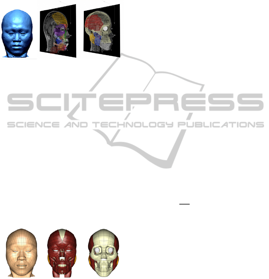
Figure 1: 3D data cloud of the segmented skin surface
(left), muscles of facial expression (centre) and deep
structures (right).
2.2 Finite Element Model
A complex network of muscles is found inside the
superficial fascia of the face, where it is tightly
connected to the surrounding adipose and connective
tissues (Mendelson, 2009). To model this behaviour,
a finite element volume (3D) mesh was created for
the entire superficial soft tissue mass consisting of
skin, subcutaneous layer and the superficial
musculo-aponeurotic system (SMAS) (Mitz and
Peyronie, 1976). Moreover, finite element meshes of
individual muscles, glands and skeletal bones were
also generated. Some of the muscles (specifically,
the muscles of facial expression) were embedded
inside the superficial fascia to account for varying
mechanical properties, while deep structures were
regarded as separate entities which mechanically
interact with the superficial continuum mesh. Figure
2 shows the geometric meshes created by fitting to
the segmented data.
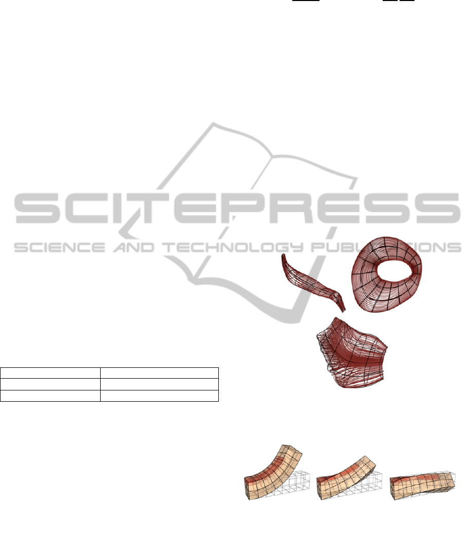
Figure 2: Fitted geometric meshes of the superficial soft
tissue continuum (left), muscles of facial expression
(centre) and deep structures (right).
Since the muscles of facial expression are
embedded inside the deformable superficial
continuum mesh, these muscles do not introduce
additional degrees of freedom to the problem. In
total, the continuum model is composed of 229
volume elements and 493 nodes interpolated using
cubic-Hermite basis functions (Bradley et al., 1997).
Cubic-Hermite interpolations were used as they
provide C
1
-continuous displacement field therefore
satisfying moment balance during large bending and
torsional deformations (Desai and Kundu 2001).
2.2.1 Correction for Gravity
The MRI data were acquired with the subject lying
in supine position due to limited space inside the
MRI scanner. This is different to an animation
setting, where the head is usually in an upright pose.
As a consequence, the gravity induced deformations
were different. Since gravity is neglected in this
study, the reference state for the mechanical analysis
is defined to be at the upright position. The upright
configuration for the finite element model was
determined by fitting the superficial continuum
mesh to the neutral expression (all muscles relaxed)
structured-light surface data acquired in the upright
position. The underlying muscles were also
customised to reflect the new configuration. The
fitting and customisation procedures employed in
this paper are documented in detail in (Fernandez et
al., 2004).
2.3 Finite Deformation Elasticity and
Contact Modelling
The governing equation for a 3D continuum under
static equilibrium is given as
0
(1)
where
are the components of the Cauchy
stress tensor,
are spatial coordinates, and
are
the components of the body force vector. In this
study body forces were neglected and hence
removed from the governing equation. The facial
soft tissues were assumed to be hyperelastic and
were approximated using the two-parameter
Mooney-Rivlin constitutive model.
̅
3
̅
3
(2)
Here, is the strain energy density function,
and
are the material parameters,
̅
and
̅
are the
isochoric strain invariants (Flory, 1961).
Furthermore, the material was assumed to be
incompressible in which the incompressibility
constraint is enforced using the method of Lagrange
multipliers.
To avoid penetrations between the continuum
GRAPP2013-InternationalConferenceonComputerGraphicsTheoryandApplications
268
mesh and the deep structures, surface to surface
contact constraints were imposed using the penalty
method. In addition, certain nodes of the continuum
mesh were precisely positioned to represent
attachment locations of the ligaments and muscle
origins where displacement boundary constraints
were placed to mimic these fixation sites.
2.3.1 Material Heterogeneity
Material heterogeneity of the facial soft-tissues
arises from the integrated structures of different
tissue types such as muscles, fat (adipose tissue),
aponeurosis and other connective tissues. In addition,
local variations within each tissue type also
contribute to heterogeneous mechanical response.
Since it is impractical to model all structural
variations, only the heterogeneity caused by the
elastic difference between the muscular and adipose
tissues were modelled.
The distribution of these two tissues was
represented as a percentage of the volume occupied
by each constituent. Accordingly, a finite element
field can be used to describe the variation of these
percentages across the computational domain. The
material parameters assigned for the 100% muscular
and 100% adipose tissues are given in table 1,
whereas the regions with mixed percentage of
materials were linearly interpolated based on the
relative fraction.
Table 1: Mooney-Rivlin material parameters.
Fat (Tran et al., 2007) Muscle (Nazari et al., 2010)
0.42kPa
2.500kPa
0.00kPa
1.175Pa
2.3.2 Muscle Mechanics
The mechanical contribution of the muscle structure
depends primarily on the response of its constituents,
namely, the muscle fibres and surrounding matrix.
Muscle fibres are responsible for the active
contraction of the muscle structure. It is well-known
that the active tension produced by a muscle fibre is
a function of its stretch (
⁄
), where
and
are the reference and current fibre lengths
respectively. For skeletal muscles, active tension
curve has a maximum at the experimentally
determined optimal fibre stretch
. In addition, it
is also observed that muscle fibres developed
passive restorative forces when elongated beyond
the optimal fibre stretch (Zajac, 1989). The total
stress produced by muscle fibres is given as
∂
∂
∂
∂
(3)
where
is the maximum active stress developed
by the fibre at the optimal stretch, is the level of
activation,
and
are the normalised active
and passive fibre tension respectively given by the
classical force-stretch relationship (Blemker et al.,
2005) and
are the components of the fibre axes.
Moreover, the fibres in some muscles are
arranged in an oblique angle to the muscle length,
such as the buccinator muscle. To describe the
locally varying fibre directions, Euler angles were
introduced to rotate the fibre axis (Mithraratne et al.,
2010). Figure 3 illustrates the fibre arrangement of
three of the facial muscles. For the present studies,
these information were obtained by consulting
anatomical literature. Figure 4 demonstrates the
importance of the fibre orientation in obtaining
physiologically realistic deformations.
Figure 3: Muscle fibre arrangement of the zygomaticus
major muscle (left), orbital belly of the orbicularis oculi
muscle (centre) and the buccinator muscle (right).
Figure 4: Deformation of a rectangular beam as a result of
activation of a muscle slab embedded inside the beam.
Showing muscle fibre angles of (from left to right) 0
°
, 36
°
and 60
°
from the longitudinal axis of the beam.
3 SIMULATION RESULTS
Most complex facial expressions can be obtained as
SimulatingandValidatingFacialExpressionsusinganAnatomicallyAccurateBiomechanicalModelDerivedfromMRI
Data-TowardsFastandRealisticGenerationofAnimatedCharacters
269
a combination of elementary actions produced from
single muscles. It is useful to visualise the individual
muscle actions before designing an input parameter
space (level of activations) for a given facial
expression. Therefore, a series of exploratory
simulations were conducted by activating one
muscles at a time (see figure in the Appendix).
In this section, four well-known facial
expressions were generated using the developed
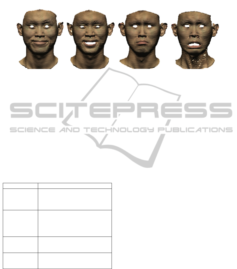
model. Figure 5 depicts the surface data cloud
obtained from 3D structured light scanner for these
expressions. The muscles employed to produce these
expressions are listed in Table 2.
Table 2: Muscles employed for the facial expressions
simulated.
expression Activated muscles
Smile
(mouth closed)
Buccinator, levator anguli oris,
orbicularis oculi (orbital part), risorius,
zygomaticus major and zygomaticus
minor.
Smile
(mouth opened)
Depressor labii inferioris, levato
r
anguli oris, levator labii superioris
alaeque nasi, orbicularis oculi (orbital
p
art), zygomaticus major an
d
zygomaticus minor.
Sad
Corrugator, depressor anguli oris,
frontalis, mentalis, orbicularis oris,
platysma and risorius.
Terror
Depressor anguli oris, depressor labii
inferioris, frontalis, mentalis,
p
latysma
and risorius.
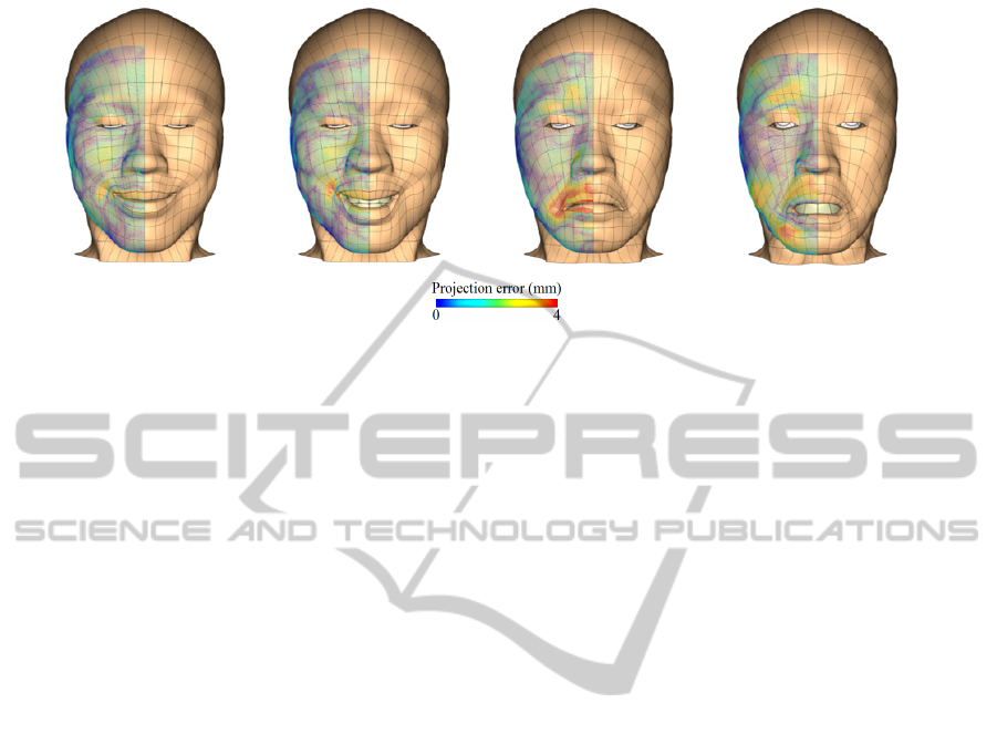
The simulation results are shown in Figure 6,
with each simulation took approximately 2 hours on
a standard quad-core computer (2.4GHz). Prediction
error was estimated by projecting the structured-
light surface data (Figure 5) to the deformed
configurations obtained from the model (Figure 6).
The RMS errors were 0.88mm, 0.93mm, 1.43mm,
1.40mm for smile with mouth closed, smile with
mouth opened, sad and terror expressions
respectively. In all simulations, higher errors (>4mm)
were observed at the corners of the lips due to more
significant displacements. Moreover, in the sad
expression, protrusion of the lips was seen in the
scanned data which was not captured in the
simulations. This is possibly due to the fact that the
orbicularis oris and levator muscles were also
activated when the subject was asked to perform the
expression. It shall also be noted that, in this study,
the activation parameters were heuristically assigned
from experience; smaller projection errors may be
achieved if these parameters (level of activations)
were determined by optimising (minimising) against
the data error.
4 CONCLUSIONS AND FUTURE
WORK
A high-order, heterogeneous finite element model of
the head was developed. The deformed state of the
model was predicted using physical theory governed
by finite deformation elasticity. In addition to
material heterogeneity, anisotropic property was also
introduced by embedding anatomically accurate 3D
muscles with preferential fibre direction. The
simulated deformation from the model has shown
good match with experimental data where the errors
can be further minimised through a more rigorous
parameter identification procedure.
This model is a part of the framework that is
currently being developed towards a biophysically
based computational model for facial expression
simulations. With further development, this model
will also be useful in the medical sector, such as
predicting the muscular functions after plastic and
reconstructive operations. While solving these
nonlinear mechanics equations are time consuming
Smile (mouth closed) Smile (mouth opened) Sad Terror
Figure 5: 3-D surface data of four primary facial expressions obtained from structured-light 3D scanner.
GRAPP2013-InternationalConferenceonComputerGraphicsTheoryandApplications
270
and not practical for interactive applications, they
can be useful in generating data sets for fast
surrogate-based modelling (Queipo et al., 2005).
Work on the surrogate-based modelling technique is
already underway. In addition, using appropriate
fitting and customisation procedures, the detailed
finite element model developed in this study can be
readily morphed into another subject, hence
reducing the manual intensive effort when creating a
population of face models.
ACKNOWLEDGEMENTS
The work presented in this paper was funded by
Foundation for Research, Science and Technology
of New Zealand under the grant number
UOAX0712.
REFERENCES
Barbarino, G. G., Jabareen, M., Trzewik, J., Nkengne, A.,
Stamatas, G. & Mazza, E., 2009. ‘Development and
validation of a three-dimensional finite element model
of the face’, Journal of Biomechanical Engineering,
vol. 131, no. 4, pp. 041006.
Blemker, S. S., Pinsky, P. M. & Delp, S. L., 2005. ‘A 3D
model of muscle reveals the causes of nonuniform
strains in the biceps brachii’, Journal of Biomechanics,
vol. 38, pp. 657-665.
Bradley, C. P., Pullan, A. J. & Hunter, P. J., 1997.
‘Geometric modeling of the human torso using cubic
hermite elements’, Annals of Biomedical Engineering,
vol. 25, pp. 96-111.
Chabanas, M. & Payan, Y., 2000. ‘A 3D finite element
model of the face for simulation in plastic and
maxillo-facial surgery’, Lecture Notes in Computer
Science, vol. 1935/2000, pp. 411-496.
Desai, C. S. & Kundu, T., 2001. Introductory finite
element method, CRC Press, Boca Raton.
Fernandez, J. W., Mithraratne, P., Thrupp, S. F., Tawhai,
M. H. & Hunter, P. J., 2004. ‘Anatomically based
geometric modelling of the musculo-skeletal system
and other organs’, Biomechanics and Modeling in
Mechanobiology, vol. 2, no. 3, pp. 139-155.
Flory, P. J., 1961. ‘Thermodynamic relations for high
elastic materials’, Transactions of the Faraday Society,
vol. 57, pp. 829-838.
Gladilin, E., Zachow, S., Deuflhard, P. & Hege, H. C.,
2004. ‘Anatomy- and physics-based facial animation
for craniofacial surgery simulations’, Medical and
Biological Engineering and Computing, vol. 42, pp.
167-170.
Grioli G., 1997. ‘Comparison between finite and linear
elasticity’, Applicable Analysis, vol. 65, no. 1-2, pp.
145-151.
Mendelson, B., 2009. ‘Facelift anatomy, SMAS, retaining
ligaments and facial spaces’, in Aesthetic plastic
surgery, eds S. J. Aston, D. S. Steinbrech & J. walden,
Saunders, Edinburgh.
Mithraratne, K., Hung, A., M.Sagar & Hunter, P. J., 2010.
‘An efficient heterogeneous continuum model to
simulate active contraction of facial soft tissue
structures’, in 6th World Congress of Biomechanics
(WCB 2010); August 1-6, 2010, eds C. T. Lim & J. C.
H. Goh, Springer, Berlin.
Mitz, V. & Peyronie, M., 1976. ‘The superficial musculo-
aponeurotic system (SMAS) in the parotid and cheek
area’, Plastic and Reconstructive Surgery, vo. 58, pp.
80-88.
Nazari, M. A., Perrier, P., Chabanas, M. & Payan, Y.,
2010. ‘Simulation of dynamic orofacial movements
using a constitutive law varying with muscle
activation’. Computer Methods in Biomechanics and
Biomedical Engineering, vol. 13, pp. 469-482.
Queipo, N. V., Haftka, R. T., Shyy, W., Goel, T.,
Vaidyanathan, R. & Tucker, P. K., 2005. ‘Surrogate-
Smile (mouth closed) Smile (mouth opened) Sad Terror
Figure 6: Numerical simulations of four primary facial expressions, showing the projection errors between the simulated
deformed configuration and structure-light surface data.
SimulatingandValidatingFacialExpressionsusinganAnatomicallyAccurateBiomechanicalModelDerivedfromMRI
Data-TowardsFastandRealisticGenerationofAnimatedCharacters
271
based analysis and optimization’, Progress in
Aerospace Sciences, vol. 41, no. 1, pp. 1-28.
Sifakis, E., Neverov, I. & Fedkiw, R., 2005. ‘Automatic
determination of facial muscle activations from sparse
motion capture marker data’. ACM Transactions on
Graphics, vol. 24, pp. 417-425.
Tran, H. V., Charleux, F., Rachik, M., Ehrlacher, A. & Ho
Ba Tho, M. C., 2007. ‘In vivo characterization of the
mechanical properties of human skin derived from
MRI and indentation techniques’, Computer Methods
in Biomechanics and Biomedical Engineering, vol. 10,
pp. 401-407.
Zajac, F. E., 1989. ‘Muscle and tendon: properties, models,
scaling, and application to biomechanics and
motor ,control’, Critical Reviews in Biomedical
Engineering, vol. 17, pp. 359-411.
Zhang, Y., Sim, T., Tan, C. L. & Sung, E., 2006.
‘Anatomy-based face reconstruction for animation
using multi-layer deformation’, Journal of Visual
Languages and Computing, vol. 17, pp. 126-160.
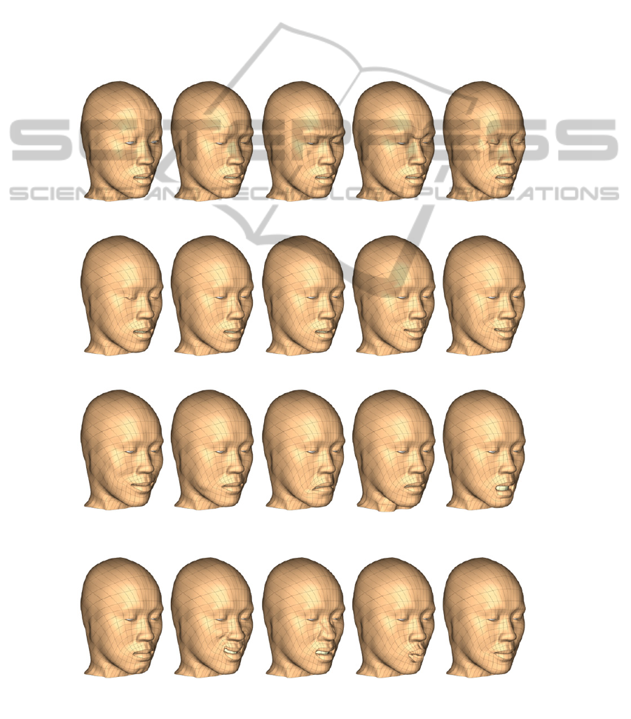
APPENDIX
Frontalis Corrugator
Depressor
supercilii
Procerus
Orbicularis oculi
(orbital)
Orbicularis oculi
(palpebral)
Nasalis
Depressor septi
nasi
Levator anguli
oris
Zygomaticus
minor
Zygomaticus
major
Risorius
Depressor
anguli oris
Platysma
Depressor labii
inferioris
Mentalis
Levator labii
superioris
Levator labii
superioris
alaeque nasi
Orbicularis oris Buccinator
Figure A: Simulated deformations due to individual muscle actions.
GRAPP2013-InternationalConferenceonComputerGraphicsTheoryandApplications
272
