
FPGA Implementation of Hodgkin-Huxley Neuron Model
Safa Yaghini Bonabi
1
, Hassan Asgharian
2
, Reyhaneh Bakhtiari
1,3
, Saeed Safari
1
and Majid Nili Ahmadabadi
1,3
1
School of Electrical and Computer Engineering, College of Engineering, University of Tehran, Tehran, Iran
2
Department of Computer Engineering, IUST, Tehran, Iran
3
School of Cognitive Sciences, Institute for Research in Fundamental Sciences (IPM), Tehran, Iran
Keywords: Hodgkin-Huxley, FPGA, VHDL, MATLAB.
Abstract: In this paper an implementation of Hodgkin-Huxley single neuron is provided. Unlike almost all of the
existing implementations, the arithmetic logics are implemented with computation techniques (i.e.
CORDIC) and look-up-tables (LUTs) are used only in few modules. This makes our design more robust and
flexible to simulate the functionality of a large network of neurons. Most of the previous works are based on
the software implementations which overshadow the parallel nature of the neural system or using LUTs for
hardware implementation which needs more space and also limited flexibility. In this paper, an FPGA is
selected as our hardware implementation platform to provide an appropriate reconfigurable platform for
simulating the functionality of a network of neurons. We validated our design based on our high level
implementation of Hodgkin-Huxley neuron in MATLAB and report our implementation results based on
Xilinx SPARTAN 3 FPGA in Xilinx ISE Design Suite.
1 INTRODUCTION
There has been a recent interested in computational
neuroscience, which tries to reveal how the brain
processes information, based on the functionality
and the relationship between different parts of the
nervous system. Neurons are considered as the basic
building blocks of the nervous system. They are
excitatory/inhibitory cells that receive electrical
signals from other neurons, combine them, and
transmit them to other neurons through their short or
long axons. To perform a specific function, up to
thousands neurons may interconnect to each other in
a neural network. It is of special interest to develop
computational tools to simulate the behaviour of
neurons, and verify the theories that were proposed
to justify the results of experiments (Kandel et al.,
2000).
Transient, as well as the steady state, response of
each neuron affects the behavior of all neurons
connected to it. This dynamic interaction among the
neurons seems to be very important in functionality
of the neural networks. Such an interaction cannot
be implemented in a serial system. Therefore,
modeling parallelism as well as dynamic interaction
of the neurons is essential.
A neuron can be modeled in two ways: software
simulation and hardware implementation. Software
simulation has a serial nature (Li et al., 2010) and, as
a result, simulation of transient interaction of the
neurons is very difficult in software simulation. In
addition, it is slower in comparison to the hardware
implementation. Moreover, due to the required large
number of interconnected neurons in a neural
network, hardware implementation provides the
results in a reasonable time. There are two different
hardware implementation approaches: analog and
digital implementations. Digital implementation is
widely used because of its lower noise sensitivity,
more flexibility, easier testability and repeatability
(Muthuramalingam et al., 2008). In addition, digital
implementation has lower design time and cost
(Gatet et al., 2009). Nevertheless, it is easier to
model dynamic interaction of the neurons in
analogue systems but the main deficiency of digital
implementation is the limited available area which
demands more optimal designs.
There are different alternatives for digital
implementation; including ASIC, DSP, and FPGA.
The ASIC-based implementation is not suitable
because it is not reconfigurable and it cannot be
changed after manufacturing (Wanhammar, 1999).
The key feature of DSP-based implementation is
522
Yaghini Bonabi S., Asgharian H., Bakhtiari R., Safari S. and Nili Ahmadabadi M..
FPGA Implementation of Hodgkin-Huxley Neuron Model.
DOI: 10.5220/0004152605220528
In Proceedings of the 4th International Joint Conference on Computational Intelligence (NCTA-2012), pages 522-528
ISBN: 978-989-8565-33-4
Copyright
c
2012 SCITEPRESS (Science and Technology Publications, Lda.)

that, it is sequential and the neurons cannot be easily
modelled in a parallel architecture. In other words,
DSP-based systems are special purpose
implementation of processor-based system. FPGAs
benefit from reconfigurable and parallel architecture
and these properties make them the best candidate
for neuron’s implementation (Muthuramalingam et
al., 2008).
Several FPGA implementations of biological
neurons have been proposed so far (Graas et al.,
2004); (Mokhtar et al., 2008); (Rice et al., 2009);
(Pourhaj and Teng, 2010) that most of them
implemented Izhikevich models (Mokhtar et al.,
2008); (Rice et al., 2009). In this paper, we are
interested to implement a more biologically
plausible neuron model. For this purpose, the
Hodgkin-Huxley (H-H) neuron model is chosen. In
(Graas et al., 2004); (Pourhaj and Teng, 2010), the
H-H neuron model has been implemented. E. L.
Graas et al. (Graas et al., 2004) used look-up-table
(LUT) instead of implementing equations for
calculating the critical parts of the implementation.
So, this type of implementation needs a large size of
memory to pre-compute the required results (of
course with limited number of bits) and save them in
LUTs which reduces the final accuracy because of
constraints on the memory size. In addition, in
(Graas et al., 2004) a neuron was implemented using
System Generator but it is obvious that automatic
software tools cannot produce an optimal hardware.
P. Pourhaj et al. (Pourhaj and Teng, 2010) used LUT
to implement different parts, which has a side effect
on the final accuracy of the implementation. For
instance, the LUT-based implementation of some
equations with the exponential terms has not (and
also can not) enough accuracy.
In this paper the H-H neuron model is used for
implementation. We employ MATLAB for high
level design of a single neuron’s behavior and use
the results as a gold standard to check our
implementation on FPGA. The rest of the paper is
organized as follows. In Section 2 the H-H model is
briefly explained. The FPGA implementation details
are discussed in Section 3. In Section 4 experimental
results are provided and finally Section 5 concludes
the work and provides the future works.
2 HODGKIN HUXLEY MODEL
In a series of experiments carried out on the squid
giant axon, Hodgkin and Huxley introduced a model
to explain the process of action potentials generation
in the neuron, based on ionic current through the
membrane (Hodgkin and Huxley, 1952). Voltage-
dependent ion channels for potassium and sodium
control flow of these ions. All other ions (mostly
chloride ions) that flow through the neuron
membrane constitute the leak current. Concentration
and electrical potential gradients are two forces
driving ions passing through the membrane
channels. The electrical potential, in which these two
forces become equal and the net flowing currents
becomes zero, is called equilibrium rest state. It is
about -65 mV and may vary in different neurons. If
the neuron is stimulated by an external current, or
through other up-stream neurons, the potential of
neurons increases to a positive value and after a
short time falls back to the equilibrium rest potential
(Izhikevich, 2007). This abrupt change in membrane
voltage is called action potential. The Hodgkin &
Huxley proposed circuit for squid giant axon is
shown in figure 1, and equation (1) gives the relation
between input current and the membrane voltage.
Figure 1: Hodgkin & Huxley proposed circuit for squid
giant axon. g
K
& g
Na
, are voltage-dependent conductance.
The complete set of H-H current’s equations
according to (Izhikevich, 2007) comes in (1) to (4).
CV = - - -
IIII
ext K Na L
(1)
Where, the potassium current,
I
K
is given by
equation (2).
4
=n(V-)
g
IE
KK
K
(2)
I
K
is the potassium current with four activation
gates which is shown by n
4
.
I
Na
is the sodium current that is defined in
equation (3). It has three activation gates (m
3
) and
one inactivation gate (h).
3
=mh(V-)
g
IE
N
aNa
Na
(3)
I
L
is the ohmic leak current which is given in
equation (4).
FPGAImplementationofHodgkin-HuxleyNeuronModel
523

=(V-)
g
IE
LL
L
(4)
According to (Hodgkin and Huxley, 1952), the
values of activation and inactivation’s parameters
are updated by equation (5).
X (V)-X
X=
(V)
τ
X
(5)
Where
X
∈
{m, n, h} and
τ (V)
X
and
X(V)
are
obtained by (6).
1
τ (V) =
X
α (V) + β (V)
XX
α (V)
X
(V) =
X
α (V) + β (V)
XX
(6)
α and β ‘s equations are shown in (7).
0.01(V + 55)
(V) =
α
n
1- exp[-0.1(V + 55)]
0.1(V + 40)
(V) =
α
m
1-exp[-0.1(V +40)]
(V) = 0.07exp[-0.05(V + 65)]
α
h
(V) = 0.125exp[-0.0125(V + 65)]
β
n
(V) = 4.0exp[-0.0556(V + 65)]
β
m
1
(V) =
β
h
1+exp[-0.1(V +35)]
(7)
According to (Izhikevich, 2007), typical values of
maximal conductance and the membrane
capacitance are shown in equation (8).
22
gg
= 36mS / cm , = 120mS / cm ,
KNa
22
g
=0.3mS/cm ,C=1μF/cm
L
(8)
The equilibrium potentials are shown in equation
(9).
= -54.402mV, = -77mV, = 50mV
EEE
LKNa
(9)
For digital implementation of these calculations, we
need to convert these floating point values and
computations to specific fixed point values and then
perform these computations with specific accuracy
in fixed point arithmetic. In the following section,
the details of our fixed point design and digital
implementation is expressed.
3 FPGA IMPLEMENTATION
According to the equations (1) - (7), the proposed
architecture which is implemented in this paper is
shown in figure 2. Each box corresponds to one or
more components. For implementing these
components, the required functionalities and
modules are addition, subtraction, multiplication,
division and exponential function. The main
constraint which should be considered in hardware
implementation is the parallelism and also optimal
hardware resource usage. In other words, the
implemented system should respond in real-time and
also have comparable accuracy with software
implementation. For this reason, addition and
multiplication are implemented by FPGA’s special
circuits (DSP Cores). We also designed the division
modules using shift registers and addition to save the
area.
One of the most important and critical parts of
our hardware implementation is exponential
function. The accuracy, speed and also logic
resource usage of this module has a direct impact on
the final result. For this reason we used the
hyperbolic CORDIC algorithm to estimate the
exponential function more accurately. According to
(Ercegovac and Lang, 2003), we used the following
equations in our design and implementation
(equation 10).
-j
x[j +1] = x[j] - 2 y[j]
σ
j
-j
y[j + 1] = y[j] + 2 x[j]
σ
j
-j
-1
z[j +1] = z[j] - tan (2 )
σ
j
(10)
As shown in equation (10), shifter and adder are
needed for hardware implementation. The number of
bits used for intermediate value representation
should be selected carefully to provide the required
accuracy of the neuron. On the other hand we should
find the minimum number of bits to minimize the
FPGA resources. In other words, there is a trade-off
between accuracy and FPGA resources. We
determined the optimal representing bits for
implementation via high level simulation in
MATLAB and comparing the final results with low
level HDL simulations.
The other important part of equation (10) is
-j
-1
tan (2 )
function. It is implemented by static
ROMs or LUTs with limited rows. There exist more
accurate implementations of this function using
more hardware resources comparing the LUT
IJCCI2012-InternationalJointConferenceonComputationalIntelligence
524
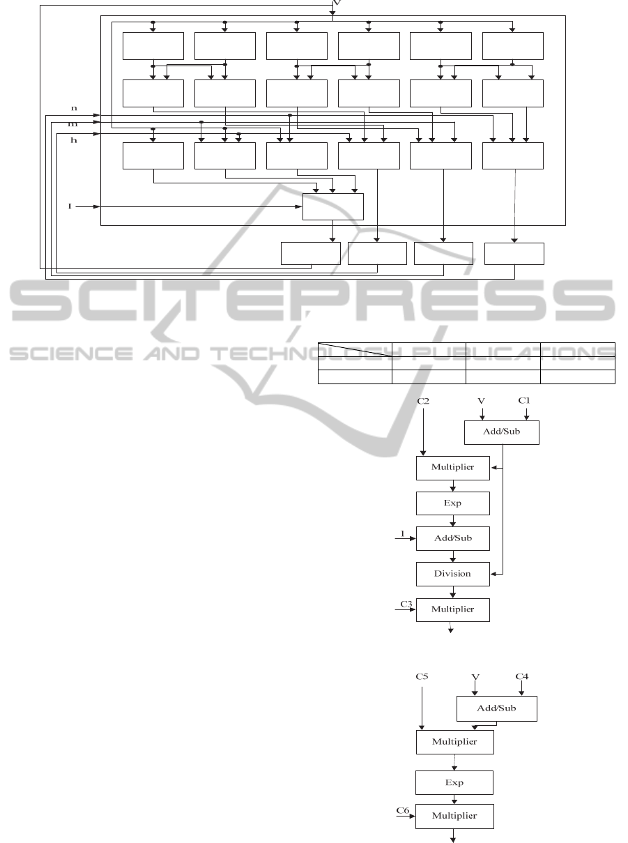
Figure 2: The proposed architecture for H-H neuron model implementation.
implementation. As we need limited accuracy, we
used LUT-based implementation to minimize the
required FPGA resources. The initial value of z[j] is
used as an argument to calculate the exponential
function. Simulation results show that 32 bit words
are enough to represent all intermediate values. As
CORDIC algorithm is defined for the limited inputs,
we separate the inputs into two parts. The most 12
significant bits are used as integer part, and the
remaining 20 bits show the fractional part of the
number. The higher 12 bits that presents the integer
part are used as LUT’s input, in which the
exponential value of this integer part is saved. In
other words, for integer numbers, the results of the
computation with adequate accuracy is computed
before, and saved in a LUT. In run-time a simple
search is performed instead of calculating its value.
As a result, the time complexity to compute this
function is O(1) and the fractional parts is given to
CORDIC algorithm. According to equation (11) the
output of the LUT and the output of the CORDIC
algorithm should be multiplied to produce the
exponential function results for 32-bit input.
θ =X+Y
exp(θ) = exp(X).exp(Y)
(11)
Based on equation (7) we use the same architecture
with different constant values to calculate α
n
and α
m
(see figure 3). The selected constant’s values used in
figure 3 are shown in Table 1.
According to equation (7), α
h
, β
n
and β
m
have
similar architecture which is shown in figure 4.
Table 2 shows the selective constant’s values used in
figure 4.
Table 1: Constant value for figure 3.
C1 C2 C3
α
n
55 -0.1 0.01
α
m
40 -0.1 0.1
Figure 3: α
n
and α
m
architecture.
Figure 4: α
h
, β
n
and β
m
architecture.
α
n
β
n
α
m
α
h
β
m
β
h
n
∞
m
∞
h
∞
τ
n
τ
m
τ
h
n
m
h
I
K
I
N
a
I
L
V
Inte
g
rato
r
Inte
g
rato
r
Inte
g
rato
r
Inte
g
rato
r
FPGAImplementationofHodgkin-HuxleyNeuronModel
525
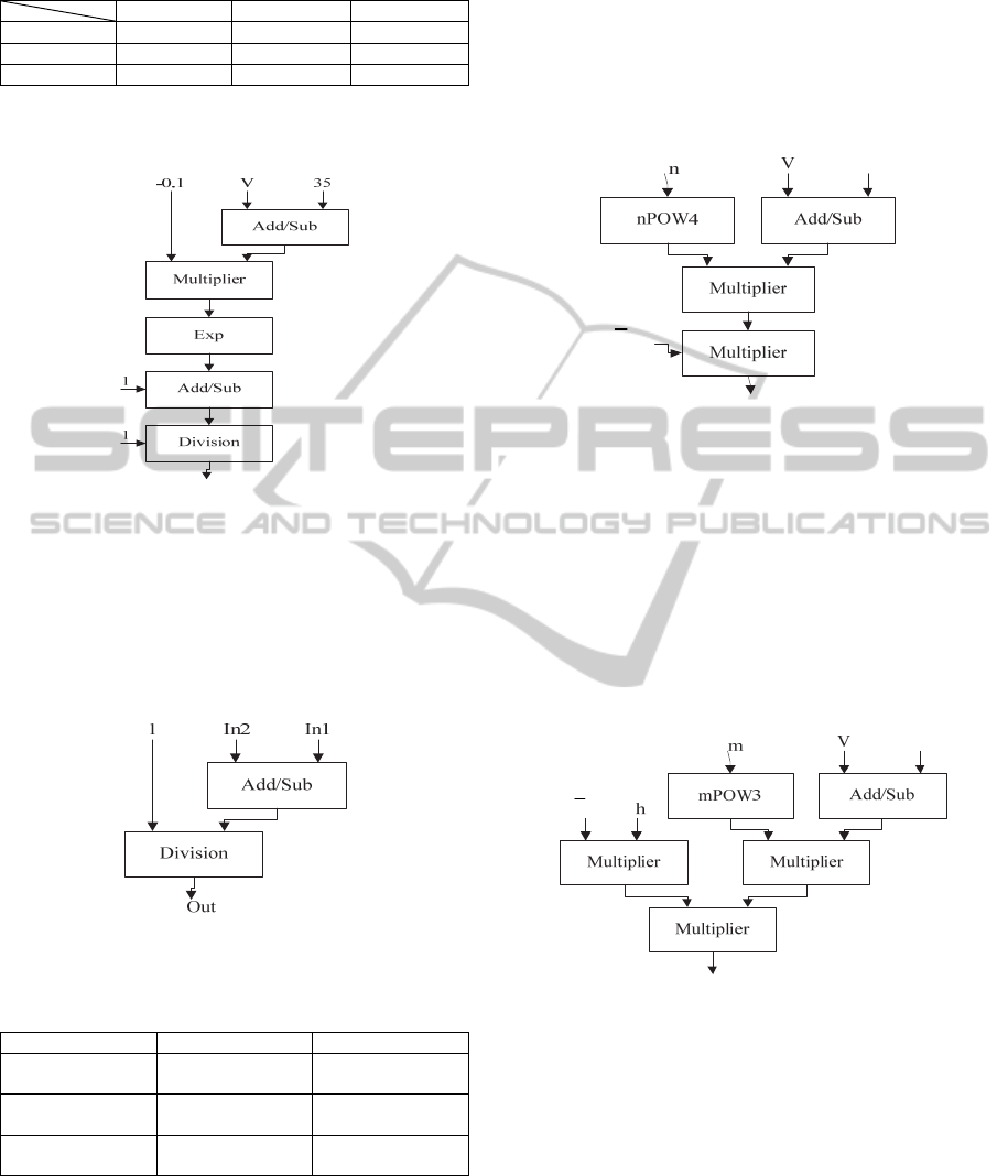
Table 2: Constant values for figure 4.
C4 C5 C6
α
h
65 -0.05 0.07
β
n
65 -0.0125 0.125
β
m
65 -0.0556 4
We used a similar architecture to calculate β
h
(See figure 5).
Figure 5: Proposed architecture to compute β
h
.
First of all, the results of the equation (7) have to
be computed, and the outputs should be produced.
So α
X
and β
X
are ready to be used as inputs in
equation (6). The high level implementation of
equation (6) that produces
τ
X
is shown in figure 6.
Inputs and output of this module are given in Table
3.
Figure 6: A typical implementation of
X
.
Table 3: The output and input`s values used in figure 6.
Out In1 In2
n
α
n
β
n
m
α
m
β
m
h
α
h
β
h
A similar architecture is used to implement X∞,
but the constant value 1 in division’s input is
replaced by the first input (In1). The outputs of these
modules which are the outputs of equation (6)
applied as inputs to equation (5). Implementation of
equation (5) is same as the architecture in figure 6,
but the first input (In1) is connected to X, and the
second input (In2) is connected to X∞ to make the
subtraction’s result and
τ
X
is connected to the
division’s input which is 1 in figure 6.
The high level circuit of
I
K
implementation is
shown in figure 7.
Figure 7: The architecture of I
K
.
Another required component which is used to
calculate
I
K
is n
4
. This function is implemented
using three multipliers (shown as nPOW4 in figure
7).
A similar circuit is designed and implemented to
compute
I
N
a
. The mPOW3 (shown in figure 8)
computes m
3
.
Figure 8: The architecture of I
Na
.
The last required component is I
L
. The
architecture of this component is shown in figure 9.
Membrane voltage in equation (1) is calculated
by the last module that is an adder with four inputs,
called I
K
, I
Na
, I
L
and I
ext
. Input I
ext
is an external
current that stimulates the neuron.
The new values of the n, m, h and V are
calculated using integrators with
n,
m,
h
and
V
as
inputs, respectively. To implement the integrator,
equation (12) is used by step time of 0.01 ms. This
step time is selected based on our design and also
E
K
I
K
g
E
Na
g
Na
I
Na
K
IJCCI2012-InternationalJointConferenceonComputationalIntelligence
526

our evaluation board which is used for prototyping.
Figure 9: The architecture of I
L
.
X(t + Δt) = X(t) + Δt*X(t)
(12)
Equation (12) is implemented using a simple MAC
(multiply and accumulate) and rounded to 32 bits. In
the following section, the experimental setup,
validation and evaluation of the proposed
architecture is described.
4 RESULTS
To validate the FPGA implementation results, the
implemented bit level simulation is compared with
MATLAB simulation system. For high level
simulation we use Simulink, and all hardware
components are designed and implemented using
VHDL modelling language. The main design
objective of the low level implementation is the
output accuracy. Due to the implementation
constraints, we should use the minimum number of
bits in all module implementations. The details of
implementation are given in Tables 4 and 5. We
tested the behavior of both systems for different
values of parameters, initial values, and external
currents. Here, the results for two important cases
are shown; i) no stimulation is applied (I
ext
= 0), and
the neuron goes to the rest state after a transition
time (Figure 10), ii) a strong stimulation (I
ext
=
30mA) is applied, and thus the neuron exhibits
periodic (tonic) spiking (Figure 11). In figure 10,
and 11, the membrane voltage (V) of the neuron
from MATLAB simulation (solid blue line), and
from FPGA implementation (dashed red line) is
shown. There are only very little differences
between the two waveforms, which are due to the
rounding error, due to the limitation of the number
of bits to 32 in FPGA implementation. This error is
in an acceptable range, and can be reduced, by
extending this number representation system.
5 10 15 20 25 30 35 40 45 50
-100
-50
0
50
Time(ms )
Voltage(mV)
Figure 10: Membrane voltage of neuron for I
ext
=0mA.
0 5 10 15 20 25 30 35 40 45 50
-60
-40
-20
0
20
40
Time(ms )
Voltage(mV)
Figure 11: Membrane voltage of neuron for Iext=30mA.
We implemented the neuron on a Xilinx FPGA
(Spartan3). The resource usages and critical path
delay are reported in Table 4 and Table 5. According
to the reported experimental results we are able to
implement one neuron in a Spartan FPGA working
with frequency of 37.563MHz. Also we can use
larger devices to implement more neurons in one
device.
Table 4: Device utilization summary.
Number of Slices 13273 out of 23872
Number of Slice FFs 7231 out of 47744
Number of 4 input LUTs 23514 out of 47744
Number of IOs 292
Number of bonded IOBs 292 out of 469
Number of GCLKs 24 out of 24
Number of DSP48s 99 out of 126
Table 5: Timing summary.
Minimum period 26.622ns
Minimum input arrival time
before clock
10.982ns
Maximum output required
time after clock
6.068ns
E
L
g
L
I
L
MATLAB simulation
FPGA implementation
MATLAB simulation
FPGA im
p
lementation
FPGAImplementationofHodgkin-HuxleyNeuronModel
527

5 CONCLUSIONS AND FUTURE
WORKS
In this paper the Hodgkin-Huxley model of a single
biological neuron has been designed and
implemented on an FPGA. Unlike previous
approaches, we used the CORDIC algorithm for
implementing the exponential functions and other
arithmetic parts. So our used logic is more compact
than previous ones. The accuracy and performance
of our proposed approach is validated by MATALB
high level implementation. Because of establishing
trade-off between used area and frequency, the
number (and also format) of representing bits of our
arithmetic parts were selected carefully and
validated and verified by high level simulation. For
instance, it was shown that the neuron spiking
frequencies in MATLAB simulation and in FPGA
implementation almost are the same. It is a very
important parameter because it codes the
information that a neuron transmits. The hierarchal
proposed design and implementation allows simple
modification of it to an equivalent small pipeline
system, which is useful in implementing a large
neural network. We plan to optimize our hardware to
make it smaller and finding the optimal bit length of
each parameter separately. Moreover, the behaviour
of the implemented neuron will be benchmarked
against the behaviour of a natural one. Furthermore,
implementing a neural network of competing
minicolumns (Bakhtiari. et al., 2012) in FPGA is the
next target of this research.
REFERENCES
Bakhtiari, R., Sepahvand, N. M., Ahmadabadi, M. N.,
Araabi, B. N., Esteky, H., 2012. Computational model
of excitatory/inhibitory ratio imbalance role in
attention deficit disorders. Computational
Neuroscience.
Ercegovac, M. D., Lang, T., 2003. Digital Arithmetic, 1st
ed. Morgan Kaufmann.
Gatet, L., Tap-Béteille, H., Bony, F., 2009. Comparison
between analog and digital neural network
implementations for range-finding applications.
Neural Networks, IEEE Transactions on 20, 460–470.
Graas, E. L., Brown, E. A., Lee, R. H., 2004. An FPGA-
based approach to high-speed simulation of
conductance-based neuron models. Neuroinformatics
2, 417–435.
Hodgkin, A. L., Huxley, A. F., 1952. A quantitative
description of membrane current and its application to
conduction and excitation in nerve. J. Physiol. (Lond.)
117, 500–544.
Izhikevich, E. M., 2007. Dynamical systems in
neuroscience: the geometry of excitability and
bursting. MIT Press.
Kandel, E. R., Schwartz, J. H., Jessell, T. M., others, 2000.
Principles of neural science. McGraw-Hill New York.
Li, G., Talebi, V., Yoonessi, A., Baker, C. L., Jr, 2010. A
FPGA real-time model of single and multiple visual
cortex neurons. J. Neurosci. Methods 193, 62–66.
Mokhtar, M., Halliday, D. M., Tyrrell, A. M., 2008.
Hippocampus-Inspired Spiking Neural Network on
FPGA, in: Proceedings of the 8th International
Conference on Evolvable Systems: From Biology to
Hardware, ICES ’08. Springer-Verlag, Berlin,
Heidelberg, pp. 362–371.
Muthuramalingam, A., Himavathi, S., Srinivasan, E.,
2008. Neural network implementation using FPGA:
Issues and application. International journal of
information technology 4, 86–92.
Pourhaj, P., Teng, D.H.., 2010. FPGA based pipelined
architecture for action potential simulation in
biological neural systems, in: Electrical and Computer
Engineering (CCECE), 2010 23rd Canadian
Conference On. pp. 1–4.
Rice, K. L., Bhuiyan, M. A., Taha, T. M., Vutsinas, C. N.,
Smith, M.C., 2009. FPGA implementation of
Izhikevich spiking neural networks for character
recognition, in: Reconfigurable Computing and
FPGAs, 2009. ReConFig’09. International Conference
On. pp. 451–456.
Wanhammar, L., 1999. DSP integrated circuits. Academic
Press.
IJCCI2012-InternationalJointConferenceonComputationalIntelligence
528
