
Formal Analysis of Objects State Changes and Transitions
Uldis Donins, Janis Osis, Erika Asnina and Asnate Jansone
Department of Applied Computer Science, Institute of Applied Computer Systems,
Riga Technical University, Meza iela 1/3, LV 1048, Riga, Latvia
Keywords: Topological Functioning Modelling, Functional Characteristics, Objects, Object States.
Abstract: Event-driven software systems continuously wait for occurrence of some external or internal events. When
such event is received and recognized, the system reacts by performing corresponding computations which
may include generation of events that trigger computation in other components. The response to the
received event depends on the current state of the system and underlying objects and can include a change
of state leading to a state transition. The state changes and transitions within a system can be formally
analysed by using Topological functioning model. It captures system functioning specification in the form
of topological space consisting of functional features and cause-and-effect relations among them and is
represented in a form of directed graph. The functional features together with topological relationships
contain the necessary information to create State diagram which reflects the state changes within system.
1 INTRODUCTION
The behaviour of an object over time could be
surmised by analysing system Use case descriptions,
Activity diagrams, or other software design artefact.
To avoid surmising the state change of objects in
system, a State diagram is used (Podeswa, 2009;
Scott, 2001). State diagram is a part of the Unified
Modeling Language (UML) (OMG, 2011). The
application of design models provide better
understanding of proposed solution and allows
making better decisions concerning the
implementation details. Additionally, the model
driven development has been put forward to enable
development, validation and transformation of
syntactically and semantically complete models,
thus allowing source code generation automation. In
such way models are promoted as the core and main
artefact of software design and development.
Despite the presence of UML and a number of
software development methods, the way the
software is built still remains surprisingly primitive
(by meaning that major software applications are
cancelled, overrun their budgets and schedules, and
often have bad quality levels when released) (Jones,
2009). This is due that the very beginning of
software development lifecycle is too fuzzy and
lacking a good structure (Donins and Osis, 2011;
Osis et al., 2008). Instead of analysing the system,
software developers set the main focus on software
design thus leading to a gap between the problem
domain and its supporting software (Osis and
Asnina, 2011b). This issue can be overcome by
formalizing the very beginning of the software
development lifecycle. By adding more efforts at the
very beginning of lifecycle it is possible to build
better quality software systems (Donins and Osis,
2011).
Previous researches in the field of formalizing
very beginning of software development lifecycle
propose TopUML modelling that enables
functioning modelling of both the problem and
solution domains (Donins, 2010). It supports early
solution domain model validation against
functioning of the problem domain. TopUML
modelling is a model-driven approach which
combines Topological Functioning Model (TFM)
(Osis and Asnina, 2011a) and its formalism with
elements and diagrams of TopUML – a profile based
on UML (Osis and Donins, 2010). The TFM
holistically represents a complete functionality of
the system from the computation independent
viewpoint (Asnina and Osis, 2011). It considers
problem domain information separate from the
solution domain information.
The purpose of this research is to strengthen the
TopUML modelling with formal development of
State diagram thus enabling transformation from
249
Donins U., Osis J., Asnina E. and Jansone A..
Formal Analysis of Objects State Changes and Transitions.
DOI: 10.5220/0004099502490256
In Proceedings of the 7th International Conference on Evaluation of Novel Approaches to Software Engineering (MDA&MDSD-2012), pages 249-256
ISBN: 978-989-8565-13-6
Copyright
c
2012 SCITEPRESS (Science and Technology Publications, Lda.)

TFM to it and eliminating the gap between problem
domain model and software design (solution) model.
Thus the paper is organized into following sections.
Section 2 discusses the UML modelling driven
methods that supports analysis of object state
transitions and composition of corresponding State
diagrams. Section 3 explores TopUML modelling
and the prerequisites that should be satisfied in order
to formally develop State diagrams in strong
relevance with the problem domain. This section
gives the formal method of developing State
diagram based on TFM, i.e., the TFM to State
diagram transformation pattern. Section 4 shows an
example of using functional characteristics to
analyse state changes of objects based on enterprise
data synchronization system. Paper is concluded
with conclusions of the performed research.
2 RELATED WORKS
UML is a notation and as such its specification does
not contain any guidelines of software development
process (e.g., which diagrams to use in which order).
In fact this is pointed out as one of the UML
weaknesses (Kent, 2001). According to (Booch et
al., 2007) a successful software development project
can be measured against the deliverables that satisfy
and possibly exceed expectations of customer, the
delivery schedule that has occurred in a timely and
economical fashion, and the created result is resilient
to change and adaptation. For software development
project to be successful by means of given
measurements, it should satisfy the following two
characteristics:
Solution should have a strong architectural
vision, and
A well-managed development lifecycle should
be used.
This section discusses the current state of the art
of UML based software development approaches by
paying attention on one aspect – support of analysis
for object state changes and transitions:
The use of State diagrams within Unified
software development process (Scott, 2001) is
emphasized for showing system events in Use
cases, but additionally they may be applied to
any class.
Business Object-Oriented Modeling developed
by Podeswa (2009) states that At least for every
key business object a state diagram should be
created.
According to GRASP patterns introduced by
Larman (2005) the State diagrams are used to
describe allowed sequence of external system
events that are recognized and handled by a
system in the context of a use case. Additionally
State diagrams can be applied to any class.
Conceptual modelling described in (Olive,
2007) states that each entity type may be
associated with zero, one, or more State
diagrams. It can be viewed as an activity related
to capture knowledge about the desired system
functionality.
State diagrams within Component based
development are used to determine the threads
of control within the system (Stevens and
Pooley, 2005).
These methods share common viewpoint of the
application of State diagrams within software
development process:
State diagrams are developed by analysing Use
cases,
One state diagram per class or object, and
They should be developed for each most
important object within the system.
Above mentioned three statements raise a set of
ambiguousness and questions. The Use cases cannot
be considered as a complete problem domain
representation and a formal connection between
problem domain and the solution. The application of
Use cases to develop other diagrams (such as State)
depends much on the designers’ personal experience
and knowledge, thus leaving the following question
open:
How to formally eliminate and overcome the
gap between problem domain model and the
design models?, and
What are “most important objects” and how to
formally identify them?
To overcome these issues the TopUML
modelling is applied within software development as
described in the next section.
3 OBJECT STATE CHANGE AND
TRANSITION ANALYSIS BY
USING FUNCTIONAL
CHARACTERISTICS OF
PROBLEM DOMAIN
The application of TopUML modelling ensures
proper analysis of system functioning by identifying
and analysing the functioning cycles. By using
TopUML the information of system functioning
from TFM can be transferred to design models thus
allowing marking and evaluating the most important
ENASE2012-7thInternationalConferenceonEvaluationofNovelSoftwareApproachestoSoftwareEngineering
250

objects and components within system and to assign
proper responsibilities to the right objects formally.
The most important objects are the ones that are
participating in the main functioning cycle of the
system. The main functional cycle is a directed
closed loop that shows the functionality of system
which is essential to its existence. (Osis and Asnina,
2011c, and Osis and Donins, 2010)
State change analysis of objects within TopUML
consists of following activities:
TFM development (see Section 3.1),
Domain model analysis and design (see Section
3.2), and
Object state change and transition analysis (see
Section 3.3).
3.1 Topological Functioning Model
Development
During this activity a TFM representing complete
functioning of the problem domain is developed.
Afterwards the TFM is used as a source for
development of other diagrams thus overcoming the
gap between problem and solution domains (Osis et
al., 2007a and 2007b). TFM is developed by
completing following four steps:
Step 1: Definition of Physical or Business
Functional Characteristics which consists of the
following actions (Osis and Asnina, 2008): 1)
Definition of objects and their properties from the
problem domain description; 2) Identification of
external systems and partially-dependent systems;
and 3) Definition of functional features using verb
analysis in the problem domain description, i.e., by
finding meaningful verbs.
As a result a set of functional features are
defined. At the lowest abstraction level one
functional feature describes only one atomic
business action. Atomic business action means that
it cannot be further divided into a set of business
actions. The functional features are represented as
vertices in a directed graph of TFM.
Step 2: Introduction of Topology Θ (in other
words – creation of topological space) which
involves establishing cause-and-effect relations
between functional features. Cause-and-effect
relations are represented as arcs of a directed graph
that are oriented from a cause vertex to an effect
vertex. Topological space represents the system
under consideration together with the environment
in which this system exists.
Step 3: Separation of TFM from Topological
Space which is done by applying the closure
operation over a set of system’s inner functional
features (Osis and Asnina, 2011a). Construction of
TFM can be iterative. Iterations are needed if the
information collected for TFM development is
incomplete or inconsistent or there have been
introduced changes in system functioning or in
software requirements. The TFM development steps
1 to 3 can be partly automated as shown in (Slihte,
2010) where the business use cases are automatically
transformed into TFM.
Step 4: Identification of Logical Relations
between cause-and-effect relationships consists of
two actions – there are two kinds of logical
relationships (between arcs that are outgoing from
functional features and the between arcs that are
incoming to functional features): 1) identification of
logical relations between cause-and-effect
relationships that are outgoing from functional
feature, and 2) identification of logical relations
between cause-and-effect relationships that are
incoming to functional feature. Each logical relation
consists of two or more cause-and-effect
relationships and a relation type. Within TFM can be
defined three types of logical relations: 1)
Conjunction (and), 2) Disjunction (or), and 3)
Exclusive disjunction (xor).
An example of TFM consisting of nine
functional features, nine cause-and-effect
relationships and three logical relations is given
below in Figure 1.
2 3 4
5
6
789
10
AND
XOR
OR
Logical relation OR
between incoming arcs
of functional feature 3
Logical relation XOR between
outgoing arcs of functional
feature 8
Topological relationship
between cause functional
feature 5 and effect
functional feature 6
Functional feature
Figure 1: Example of TFM.
Mappings between TFM and State Diagram.
Mappings between elements of TFM and State
diagram are described in the form of table (see Table
1) by giving corresponding elements of TFM and
State diagram together with a description of each
mapping.
FormalAnalysisofObjectsStateChangesandTransitions
251
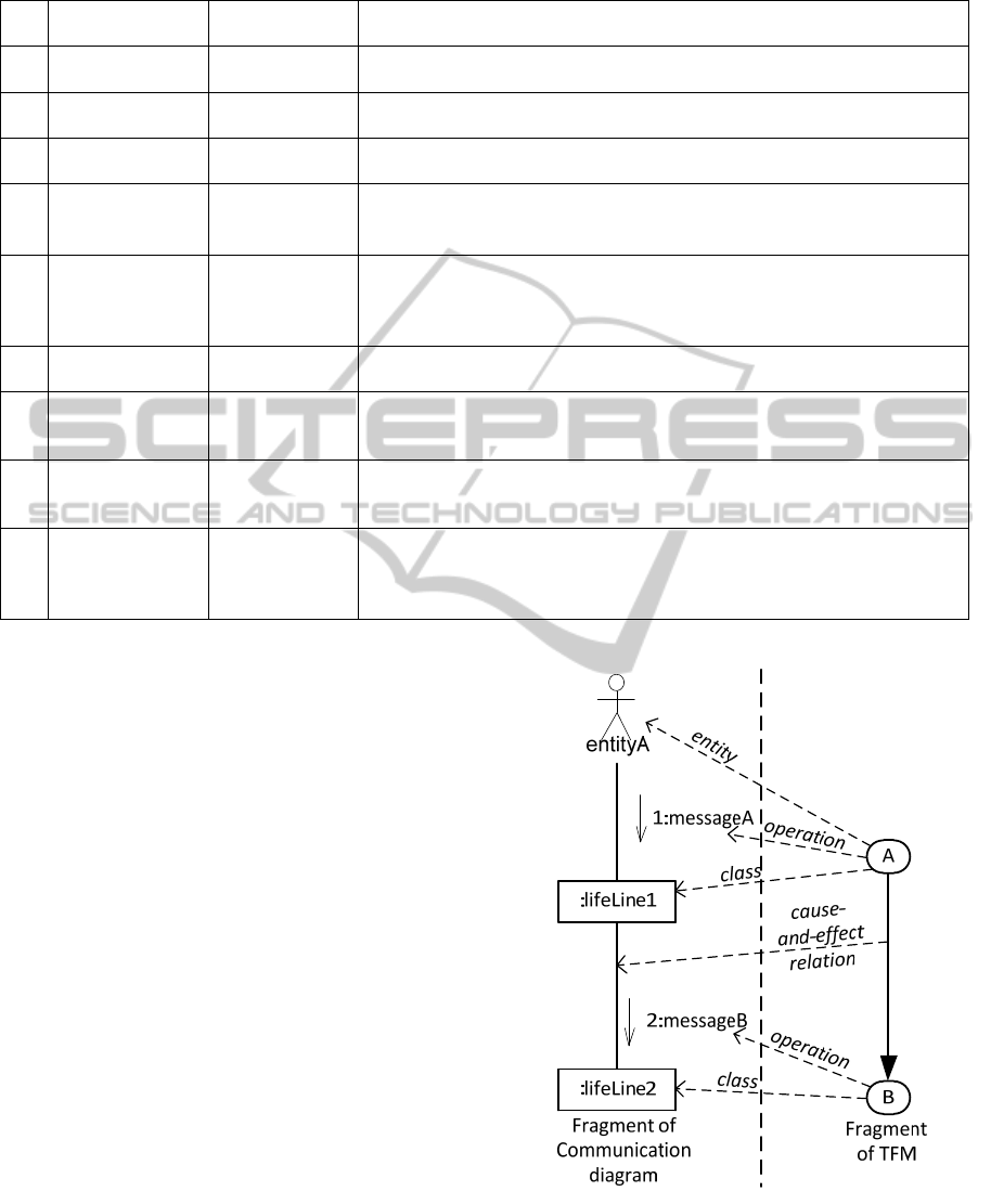
Table 1: Mappings between elements of TFM and elements of State diagram.
No TFM element
State diagram
element
Description
1
Object state
1
State
If execution of functional feature’s action changes the state of object
performing this action, it specifies the new state of the object.
2
Object state
1
Initial state
When information from input feature is transformed into a state, an initial
state is added before this state.
3
Object state
1
Final state
When information from output feature is transformed into a state, a final
state is added after this state.
4
Cause-and-effect
relationship
Transition
If execution of functional feature’s action changes the state of object
performing this action then corresponding
cause-and-effect relationship
defines transition from previous state to the new state.
5
Operation
1
Event
Each functional feature specifies an atomic business action which later is
specified by topological operation in TFM. If functional feature specifies
the new state of object, the operation is transformed into the event
triggering transition from one state to another.
6
Operation
1
Entry effect
If current functional feature specifies the new state of object, the operation
is transformed into the entry effect of this new state.
7
Operation
1
Exit effect
If descendant functional feature specifies the new state of object, the
operation of this descendant functional feature is transformed into the exit
effect of current state.
8
Preconditions
1
Guard
condition
If current functional feature specifies the new state of object, the
preconditions of this functional feature are transformed into the guard
conditions.
9
Logical
relationship with
type “and” (and
partially “or”)
Fork and Join
A logical relation in TFM give additional information about execution
concurrency of functional features, thus conjunction (and) within State
diagram is represented with fork and corresponding join. Disjunction (or)
indicates of possible fork and join.
1
TFM element specified by functional feature
3.2 Domain Model Analysis and Design
Domain model analysis and design within TopUML
modelling is based on the Topological class diagram
and consists of the following two steps:
Step 1: Analysis of Objects and their
Communication is based on the TFM
transformation into Communication diagram (in
previous researches the Problem domain objects
graph was used instead of Communication diagram
(Osis and Donins, 2010)). This transformation can
be done automatically since TFM has all the
information that is necessary for Communication
diagram. When transforming TFM into
Communication diagram the following are used:
Functional features – source for lifeline
identification and message sending from object
to object,
Topological relationships – determines the
message sender and receiver as well as the
message sending sequence, and
Logical relations – shows the message sending
concurrency.
The first step in transformation is to merge
functional features with objects of the same type in
one lifeline. While merging functional features into
Figure 2: Example of TFM to Communication diagram
transformation.
lifelines the relationships with other lifelines should
be retained (if there is more than one topological
ENASE2012-7thInternationalConferenceonEvaluationofNovelSoftwareApproachestoSoftwareEngineering
252
relationship then only one link is added between
lifelines). Actors to Communication diagram are
added from the input functional features.
For a better understanding of TFM to
Communication diagram transformation, a small
fragment of TFM consisting of two functional
features A and B is used (see Figure 2), where A is
an input functional feature of TFM.
Step 2: Domain Model Development by means
of Topological class diagram consists of four
activities (Donins et al., 2011):
1) Adding classes and operations,
2) Adding topological relationships between
classes,
3) Identifying attributes, and
4) Refining initial Topological class diagram.
3.3 Object State Change and
Transition Analysis
Object state change and transition analysis is based on
the TFM transformation into a set of State diagrams.
The input of this activity is refined TFM and classes
(either from Topological class diagram or lifelines
from Communication diagram) and the output of this
activity is one State diagram for each class.
Each functional feature specifies an object
performing certain action. The count of obtained
State diagrams is denoted by count of distinct
objects specified by functional features. It is advised
to analyse state changes of complex or most
important objects in the system (Podeswa, 2009).
The most important objects are denoted by TFM –
the functional features that are included into main
functional cycle denote them, thus the identification
of most important objects are done in a formal way.
The first action is to scale down TFM which is
performed by removing features which does not
represent the object under consideration but in the
same time retaining cause-and-effect relations. For
example, assume that TFM consists of three features
and are in the following causal chain: A→B→C.
The A and C represent the same object while B
represents another object, thus resulting TFM is as
follows: A→C.
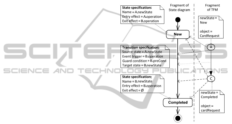
States for each class are obtained from the
functional features of refined TFM (functional
feature has an attribute that defines the new state of
the object). If the execution of functional feature
involves the change of the corresponding object’s
state, then the state attribute has value, otherwise the
value is not set. State transitions are obtained by
transforming cause-and-effect relationship between
functional features. The special states (initial state
and final state) are added to the obtained State
diagram as follows:
The initial state is added before the states that
are obtained from the functional features which
are the inputs of the downscaled TFM, and
The final state is added after the states that are
obtained from the functional features which are
the outputs of the downscaled TFM.
The example of transforming generic example of
TFM into state diagram is given in Figure 3.
Figure 3: Example of TFM to State diagram
transformation.
4 EXAMPLE OF OBJECT STATE
CHANGE AND TRANSITION
ANALYSIS
Example of object state change and transition
analysis by using functional characteristics of
problem domain is based on a case study in which
TFM is developed for enterprise data
synchronization system. The enterprise data
synchronization system is developed by applying
TopUML modelling and involves creation of TFM,
Use case diagram, Problem domain objects graph
(applied instead of Communication diagram),
Topological class diagrams, and Sequence diagrams
(Donins and Osis, 2011).
Within the case study have been defined 30
functional features by analysing functioning of
FormalAnalysisofObjectsStateChangesandTransitions
253
enterprise data synchronization system. Part of
defined functional features is given in Table 2 where
are included features that specify the new state for
object named “Scheduler”. After definition of
functional features the topology Θ (cause-and-effect
relationships) are identified between those functional
features thus creating topological space. In order to
get the TFM the closuring operation is applied over
the set of internal system functional features. The
developed TFM after applying closuring operation is
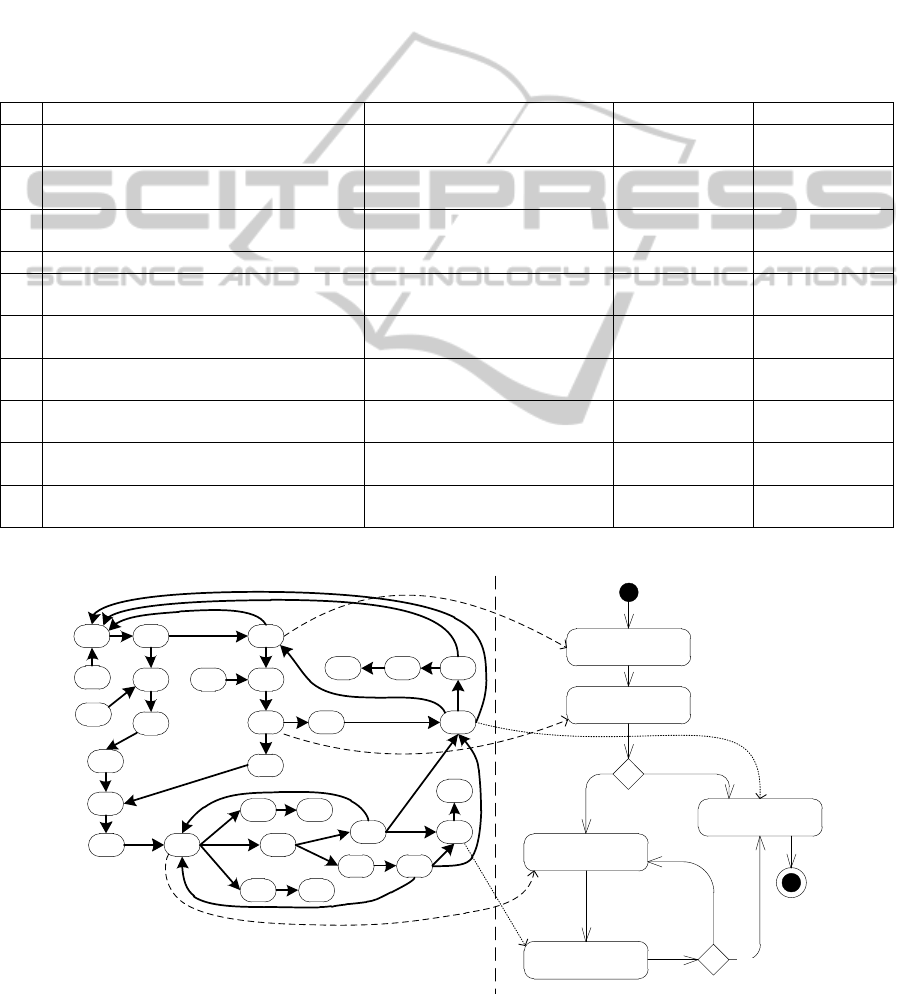
as follows: X={2, 3, 5, 6, 7, 8, 9, 11, 12, 13, 14, 15,
16, 17, 19, 20, 22, 24, 25, 26, 27, 28, 29}. The
resulting graph is given in Figure 4 (a) which shows
functional features (vertices), cause-and-effect
relationships (arcs between vertices).
The example of object state change analysis in
the context of enterprise data synchronization
system development case study is performed for the
object name “Scheduler”. The functional features
specification in Table 2 shows that this object in
total has five different states: 1) Reading data, 2)
Checking data, 3) Importing, 4) Logging status, and
5) Completing import. The resulting State diagram is
given in Figure 4 (b).
Table 2: Part of functional features defined for enterprise data synchronization system.
ID Object Action Precondition Object New State
5
Reading all data from source data base
If import should be performed
from source data base
Scheduler Reading data
6
Checking if read data structure is
according to specification
Scheduler Checking data
7
Putting the read data into temporal
internal table
If data structure is according to
specification
Scheduler Importing
9
Checking import folder Scheduler Reading data
12
Checking if import file data structure is
according to specification
Scheduler Checking data
13
Converting the read data from import file
into temporal internal table
If import file structure is
according to specification
Scheduler Importing
15
Moving import file to processed files
folder
Scheduler
Completing
import
19
Checking if data from a particular row
already exists in target data base
Scheduler Importing
25
Logging data row from temporal internal
table
Scheduler Logging status
29
Archiving log file If data import is completed Scheduler
Completing
import
2 3
5
6
7
8
9
11
12
13
14 15
1617
19
20
22
24
25
26
27 28
29
1
4
10
21
23
30
18
Reading data
Checking data
Importing
Logging status
Completing
import
[else]
[structure is
according to
specification]
[all data is
imported]
[else]
a)
b)
Figure 4: TFM of enterprise data synchronization system functioning (a) and State diagram for object “Scheduler” (b).
ENASE2012-7thInternationalConferenceonEvaluationofNovelSoftwareApproachestoSoftwareEngineering
254

5 CONCLUSIONS
The main goal of this research is to do formal
development of State diagram by analysing
functional characteristics of a problem domain. The
result of research is method for transforming TFM
into State diagram thus eliminating the gap between
problem domain model and software design
(solution) model.
UML modelling driven methods (like Unified
process, Business object oriented modelling and
Patterns based software development) manifests that
the State diagrams are developed by analysing Use
cases (more precisely: the scenario described by it),
one state diagram per class or object. In fact they say
that State diagram should be developed for each
most important object within the system. These
statements raise a set of ambiguousness and
questions. The Use cases cannot be considered as a
complete problem domain representation and a
formal connection between problem domain and the
proposed solution. The application of Use cases to
develop diagrams of other types (such as State
diagram) depends much on the designers’ personal
experience and knowledge.
The elaborated TopUML modelling (including
the State diagram development) proposes a way on
how to formally overcome the gap between problem
domain and solution domain – the first one is
represented by TFM which shows the complete
functioning of a problem domain and the latter one
is obtained by transforming TFM of a problem
domain. Moreover the TopUML enables formal
identification of the most important objects and
classes within system – they are denoted by TFM:
functional features that are included into main
functional cycle specify these objects and classes. In
contrast, the reviewed UML modelling driven
methods relies that the designers’ personal
experience and knowledge is sufficient to identify
most important objects within system. In addition
the example described in paper shows State diagram
development for the case study in which enterprise
data synchronization system has been developed by
using TopUML modelling.
This research shows that by adding additional
efforts at the very beginning of software
development life cycle it is possible to create a
model that contains sufficient and accurate
information of problem domain. By “sufficient”
meaning that this model can be transformed into
other diagrams without major re-analysis of problem
domain and by “accurate” meaning that the model
precisely reflects the functioning and structure of the
system.
ACKNOWLEDGEMENTS
This work has been supported by the European
Social Fund within the project “Support for the
implementation of doctoral studies at Riga Technical
University”.
REFERENCES
Asnina, E., Osis, J., 2011. Topological Functioning Model
as a CIM-Business Model. In Model-Driven Domain
Analysis and Software Development: Architectures
and Functions (pp. 40-64) IGI Global, USA.
Booch, G., Maksimchuk, R., Engel, M., Young, B.,
Conallen, J., Houston, K., 2007. Object-oriented
analysis and design with applications, Addison-
Wesley. USA, 3
rd
edition.
Donins, U., 2010. Software Development with the
Emphasis on Topology. In Advances in Databases and
Information Systems, Lecture Notes in Computer
Science Vol.5968 (pp. 220-228). Springer-Verlag.
Donins, U., Osis, J., 2011. Topological Modeling for
Enterprise Data Synchronization System: A Case
Study of Topological Model-Driven Software
Development. In 13th International Conference on
Enterprise Information Systems (ICEIS 2011) (pp. 87-
96). SciTePress.
Donins U., Osis J., Slihte A., Asnina E., Gulbis B., 2011.
Towards the Refinement of Topological Class
Diagram as a Platform Independent Model. In 3rd
International Workshop on Model-Driven Architecture
and Modeling-Driven Software Development
(MDA&MDSD 2011) (pp. 79.-88). SciTePress.
Jones, C., 2009. Positive and Negative Innovations in
Software Engineering. International Journal of
Software Science and Computational Intelligence,
1(2), pp. 20-30.
Kent, S., 2001. The Unified Modeling Language. In
Formal Methods for Distributed Processing: A Survey
of Object-Oriented Approaches (pp 126-151).
Cambridge University Press.
Larman, C., 2005. Applying UML and Patterns: An
Introduction to Object-Oriented Analysis and Design
and Iterative Development, Prentice Hall. USA, 3
rd
edition.
Olive, A., 2007. Conceptual Modeling of Information
Systems. Springer-Verlag. Heidelberg Berlin.
OMG, 2011. Unified Modeling Language Infrastructure
version 2.4.1. OMG.
Osis, J., Asnina, E., 2008. A Business Model to Make
Software Development Less Intuitive. In International
Conference on Innovation in Software Engineering,
(pp. 1240-1246). IEEE Computer Society CPS.
FormalAnalysisofObjectsStateChangesandTransitions
255

Osis, J., Asnina, E., 2011a. Model-Driven Domain
Analysis and Software Development: Architectures
and Functions, IGI Global, USA.
Osis, J., Asnina, E., 2011b. Is Modeling a Treatment for
the Weakness of Software Engineering? In Model-
Driven Domain Analysis and Software Development:
Architectures and Functions (pp. 1-14) IGI Global,
USA.
Osis, J., Asnina, E., 2011c. Topological Modeling for
Model-Driven Domain Analysis and Software
Development: Functions and Architectures. In Model-
Driven Domain Analysis and Software Development:
Architectures and Functions (pp. 15-39) IGI Global,
USA.
Osis, J., Asnina, E., Grave, A., 2007a. MDA Oriented
Computation Independent Modeling of the Problem
Domain. In 2
nd
International Conference on
Evaluation of Novel Approaches to Software
Engineering (ENASE 2007), (pp. 66-71). SciTePress.
Osis, J., Asnina, E., Grave, A., 2007b. Formal
Computation Independent Model of the Problem
Domain within the MDA. In 10
th
International
Conference on Information Systems and Formal
Models ISIM’07, (pp. 47 – 54). Silesian University
Press.
Osis, J., Asnina, E., Grave, A., 2008. Formal Problem
Domain Modeling within MDA. In Software and Data
Technologies, Communications in Computer and
Information Science (CCIS) Vol. 22 (pp. 387-398).
Springer-Verlag.
Osis, J., Donins, U., 2010. Platform Independent model
Development by Means of Topological Class
Diagrams. In Model-Driven Architecture and
Modeling Theory-Driven Development. SciTePress.
Podeswa, H., 2009. UML for the IT Business Analyst,
Course Technology PTR. USA, 2
nd
edition.
Scott, K., 2001. The Unified Process Explained, Addison-
Wesley. USA.
Stevens, P., Pooley, R., 2005. Using UML: Software
Engineering with Objects and Components, Addison-
Wesley. USA, 2
nd
edition.
Slihte, A., 2010. Transforming Textual Use Cases to a
Computation Independent Model. In Model-Driven
Architecture and Modeling Theory-Driven
Development, (pp 33-42). SciTePress.
ENASE2012-7thInternationalConferenceonEvaluationofNovelSoftwareApproachestoSoftwareEngineering
256
