
A Structuring Mechanism for Embedded Control Systems
using Co-modelling and Co-simulation
Xiaochen Zhang and Jan F. Broenink
Centre for Telematics and Information Technology, University of Twente, Enschede, The Netherlands
Keywords:
Model Structuring, Collaborative Modelling, Co-simulation, Embedded Control System.
Abstract:
In most embedded control system (ECS) designs, multiple engineering disciplines and various domain-specific
models are involved, such as embedded software models in discrete-event (DE) domain and dynamic plant
model in continuous-time (CT) domain. In this paper, we advocate collaborative modelling and co-simulation
to verify different aspects of the system as a whole before implementation. This paper proposes a development
approach and structuring mechanism for CT-intensive ECS designs using co-modelling and co-simulation
techniques. Based on this approach, an integrated co-model can be developed and refined using different
domain-specific languages and tools. Influences from one domain to the other can be simulated via co-
simulation and analysed in both perspectives. Our structuring and development process has been applied
to a mobile robot using this co-simulation technique. We have experienced that structuring the co-modelling
process allows us to produce co-models an co-simulations effectively. Future work is on checking for model
inconsistencies during collaboration, and provide approaches to deal with this.
1 INTRODUCTION
The nature of embedded control systems determines
that multiple engineering disciplines and various
domain-specific models are often involved. The con-
ventional way of modelling such system is to divide
the system into different engineering domains and as-
sign them to different domain experts.
However, there are some disadvantages to use this
modelling paradigm. Due to the differences between,
for instance, the software modelling tool Overture
(Overture Community, 2010) and the dynamic system
modelling tool 20-sim (Controllab Products, 2010),
distinct aspects of the system are modelled separately.
After both developments are finished and verified, the
system can be integrated and tested on the real setup
or using a prototype.
The late integration may cause fatal problems
since the impacts on each other are usually exposed
late when integration phase is reached. It will be very
costly and error-prone if engineers have to redesign
the system and change the actual device. In addition,
the lack of system-level support and communication
between domain experts may lead to entirely different
assumptions of the same system.
Hence, we advocate collaborative modelling and
co-simulation for complex embedded control syste-
ms, as being developed in the DESTECS project
(DESTECS, 2010). Integration can then be applied at
early stage of the development, and the system can be
verified as a whole before deploying to the real setup.
In our co-modelling and co-simulation terminology,
an embedded control system consists of a discrete-
event model (DE model) implementing the software
and a continuous-time model (CT model) implement-
ing the physics parts of the system, and the combina-
tion is called a co-model.
In order to construct a dependable and reusable
co-model, we propose a structuring mechanism and
design process to support the co-modelling and co-
simulation techniques.
In this paper, we restrict ourselves to dynamic-
intensive embedded control systems, in which the dy-
namic behaviour is more essential for the total be-
haviour than the software logic. The complementary
approach, in which the software logic is more essen-
tial is discussed in (Fitzgerald et al., 2012).
In this paper, Section 2 gives a brief introduction
to the technologies we used. Section 3 proposes the
structuring mechanism and design process to support
the development of a CT-intensive co-model. A case
study is followed and described in Section 4 to show
how to apply our approach in practice. Finally, Sec-
tion 5 gives the conclusion and a forward look.
131
Zhang X. and F. Broenink J..
A Structuring Mechanism for Embedded Control Systems using Co-modelling and Co-simulation.
DOI: 10.5220/0004059801310136
In Proceedings of the 2nd International Conference on Simulation and Modeling Methodologies, Technologies and Applications (SIMULTECH-2012),
pages 131-136
ISBN: 978-989-8565-20-4
Copyright
c
2012 SCITEPRESS (Science and Technology Publications, Lda.)
2 BACKGROUND
In order to achieve multidisciplinary modelling, the
CT/DE domains in our case, different modelling
paradigms and tools are required. This section intro-
duces the basic technologies and concepts we used in
our approach.
2.1 Bond Graphs and VDM
Bond graphs (Paynter, 1961) are labeled and directed
graphs, in which vertices represent submodels, and
edges, called bonds, represent an ideal energy con-
nection between the submodels. Different than block
diagrams, the bonds in bond graphs also represent a
bi-directional connection. For different physical do-
mains, such bi-directional connections are specified
as voltage and current, force and velocity, etc. Bond
graphs are domain independent which means that sys-
tems from different physical domains (e.g. electrical,
mechanical, hydraulic, etc.) can be modelled using
the same type of graphs.
In our case, the 20-sim dynamic systema mod-
elling tool is used. It supports besides bond-graph
models also block-diagram models to cover the infor-
mation domain, which means that besides modelling
the CT part, it is also possible to model DE elements.
The Real-Time Vienna Development Method
(VDM-RT) (Bjorner and Jones, 1978) is an object-
oriented language and used for modelling and
analysing of real-time embedded systems from a
discrete-event point of view. It allows explicit mod-
elling of computation times on virtual networked pro-
cessors (Verhoef et al., 2006). Operations can be im-
plemented as periodic threads which run concurrently.
VDM-RT is supported by the Overture tool built on
top of the Eclipse platform and provides a textual en-
vironment to model the discrete-event aspect of em-
bedded control systems.
2.2 Co-simulation and Co-modelling
A precondition of co-modelling and co-simulation
CT/DE models is that two domain models must be
able to talk to each other and exchange information.
For a continuous-time simulation, the state of the sys-
tem changes continuously with respect to time. For
a discrete-event simulation, only the points in time
at which the discrete state of the system changes are
computed. The co-simulation engine supported by
the DESTECS tool is used to interact with the DE/CT
models to perform co-simulation. A synchronisation
scheme is the basis of the co-simulation engine, tak-
ing care of the simultaneous execution of DE and CT
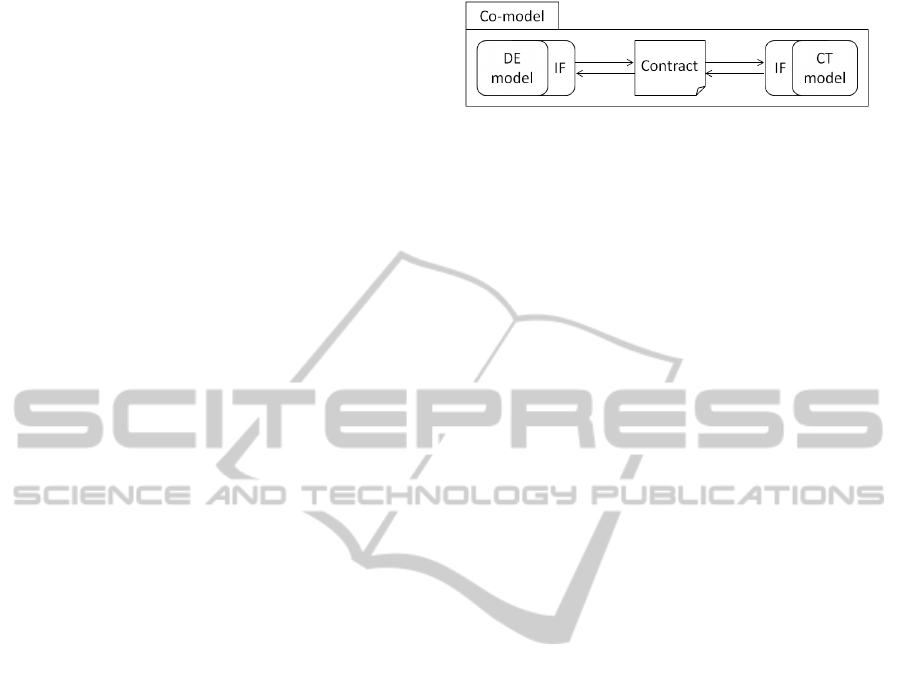
Figure 1: Conceptual view of a co-model.
models and keeping their local simulation time syn-
chronised (Fitzgerald et al., 2012).
Information sharing is achieved by defining
shared variables, parameters and events in the co-
simulation contract (see Figure 1). For example, a
discrete-event controller may control the continuous-
time velocity of an automobile by writing a steering
signal to an actuator. The steering signal can then be
considered as a shared variable which is defined in
the contract. Each domain model is connected to the
contract by attaching to a model interface (i.e. IF).
A model interface defines the shared properties of the
model that can be accessed externally.
In order to support the co-simulation technique,
we propose a structuring mechanism for the devel-
opment of dynamic intensive embedded control sys-
tems. Our intention is to, besides promote collabora-
tive modelling and simulation, also streamlining the
co-model creation process and ensure cross-domain
model consistency when constructing a co-model.
3 MODEL STRUCTURING AND
DESIGN STEPS
To support efficient development of a reliable co-
model using co-simulation technique is the ultimate
goal of our approach. The ideal way of applying co-
modelling and co-simulation is to: (1) partition the
DE/CT parts of a system and assign them to domain
experts; (2) concurrently develop the DE/CT models
based on the same abstraction and assumptions of the
system thus no need to worry about inconsistencies
between them; (3) both models are finished or reach a
certain level of maturity at the same time, such that the
co-model can be constructed and simulated using co-
simulation; and finally, (4) analyse the co-simulation
result and apply stepwise refinement or detailed engi-
neering (Broenink et al., 2007) if necessary, see Fig-
ure 2.
However, most embedded control systems in real-
ity do not always contain evenly distributed complex-
ity on two domains. One side may be more obvious or
easier to abstract than the other. Especially for motion
control systems, the dynamic behaviours and con-
trol algorithms are often more important and complex
SIMULTECH2012-2ndInternationalConferenceonSimulationandModelingMethodologies,Technologiesand
Applications
132
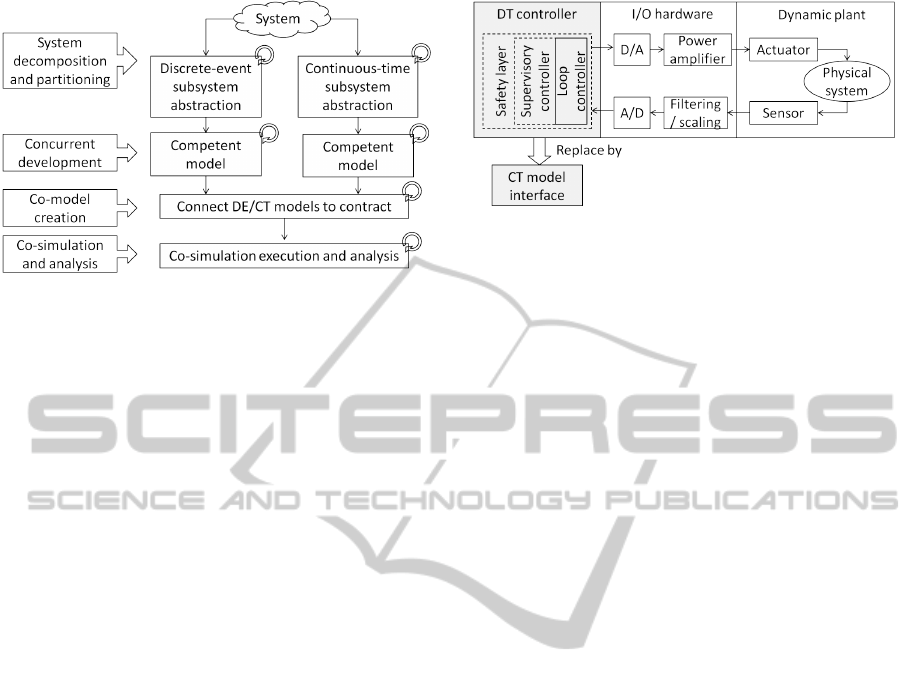
Figure 2: Ideal development process using co-modelling
and co-simulation.
than the logic controller. Therefore, our approach is
to support the development of CT-intensive systems
and construct a co-model from this point of view. The
complementary DE-intensive development approach
using co-simulation can be found in (Fitzgerald et al.,
2012)
3.1 System Level Structuring
Coping with system-level complexity and decomposi-
tion is a major non-functional requirement behind all
embedded control system designs and developments.
A CT-intensive system-level structuring mechanism is
needed to help with these non-functional / informal
problems of a system. Figure 3 illustrates the system
level structure from a CT perspective in order to test
an initial co-model. This structure is adapted from the
embedded control system architecture in (Broenink
et al., 2010). It consists of three submodels, the DT
Controller, I/O hardware and the Dynamic plant, that
are modelled using CT formalism initially.
The I/O (e.g. sensors and actuators) is treated sep-
arately in this structure because of its specific role in
the design trajectory. Inside the DT controller sub-
model, the Loop controller represents a controller that
directly communicates with the I/O and governs the
response of the plant model. For complex dynamic
systems, the control algorithms are usually complex
as well. So it makes sense to model the loop con-
troller together with the plant to verify the dynamic
behaviour, and deploy it on the virtual CPU at the DE
side for analysing the performance of the controller.
The supervisory controller and safety layer (i.e.
the dashed blocks in Figure 3) are more suitable to
model using DE formalism. A CT model interface
can then replace the entire DT controller submodel
and connect to the DE model through the contract to
construct a co-model.
We recommend this structure because it allows
Figure 3: CT-first system level structuring mechanism for
co-model integration.
different sensor, actuator and loop, sequence, super-
visory controller implementations. Continuous-time,
discrete-time or discrete-event controllers can easily
be replaced by a CT model interface to connect to
the co-simulation contract. Following this structuring
mechanism, three steps are required to accomplish the
co-model construction:
• Dynamic plant modelling and control law design.
• DT controller migration.
• Co-model integration.
Stepwise refinement is supported and design de-
cisions can be made at all stages of the development
processes listed above. This implies that modellers
can start with simple dynamic models and thus apply
simple control algorithms. Once the simulation result
fulfils the system requirements, more detailed infor-
mation can be added.
This structuring and development approach can
shorten the process of co-model integration. Both do-
main modellers are able to see the performance of the
system in their own perspective. Inconsistencies can
be examined and solved in early stages of the design
process. The following subsections describe each step
of development.
3.2 Modelling and Control Law Design
For many embedded control systems, various physical
domains are often involved, such as the electrical do-
main, the rotational/translational mechanical domain,
etc. that are interconnected to express different parts
of the system. So the structure of a dynamic model
can be further decomposed into submodels of differ-
ent mechanical parts, physical domains or functional
subsystems, and keep large-scale system organized.
Depending on different design requirements, ana-
logue (continuous in time) or digital (discrete in both
time and amplitude) loop controllers can be used in
the system. In most cases, if it is decided to use a
digital controller in the design, the control laws in the
AStructuringMechanismforEmbeddedControlSystemsusingCo-modellingandCo-simulation
133
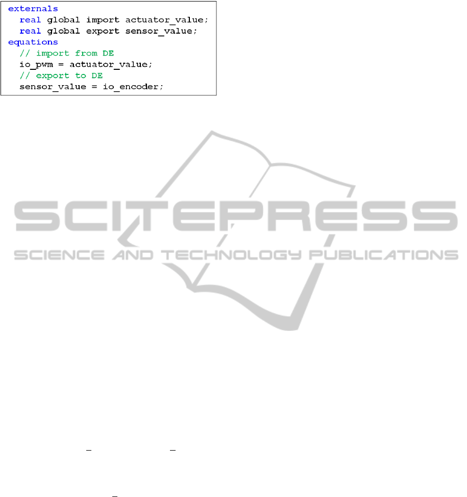
Figure 4: An example of CT model interface for connecting
to the co-simulation contract.
CT model should be implemented in the discrete-time
domain instead of the continuous one, because the
control algorithms will be eventually moved and de-
ployed on a virtual digital computer in the DE model
supported by the DESTECS tool, or in an actual mi-
crocomputer in the real device.
A continuous-time value from the dynamic plant
model cannot be computed using the discrete-time
formalism. The analog-digital conversion can be done
by means of sensors/actuators or A/D converters, and
modeled in the I/O submodel.
When the control algorithm is ready, the plant
model can be connected to the DT controller via the
I/O submodel and simulated in the 20-sim tool to ver-
ify the performance of the system. At this stage, the
20-sim model is ready for the next step towards mi-
gration.
3.3 Migration and Replacement
A model interface in our terminology defines the part
of the model which can be accessed externally, i.e.
shared variables and design parameters. Shared infor-
mation can be exchanged between models through the
model interface by the DESTECS tool. An example
of the CT model interface is illustrated in Figure 4, in
which the actuator value and sensor value are
shared variables between DE and CT models and can
be accessed by DE model externally. The CT model
imports the steering value from the DE controller and
assigns it to the variable io pwm such that this signal
can pass across domains, vice versa.
The DT controller designed in the previous phase
can be replaced by the CT model interface without
changing anything in the I/O and plant submodels.
The model interface connects the I/O submodel from
the CT side to the co-simulation contract, assuming
the shared variables between the interface and the
contract have the same identity name, data type and
range. These will be checked by the tool in order to
keep two domain models consistent.
3.4 Co-model Integration
This paper focuses on CT-intensive systems co-model
design, so hereby we assume that the DE model is
ready for co-simulation, and the DT controller devel-
oped in the CT model has been moved to the DE side
and implemented as a time-triggered loop controller.
The contract shall be specified at this stage of the de-
velopment.
An important issue of cross-disciplinary mod-
elling and co-model creation is that both domain mod-
els have to be developed based on the same assump-
tion of the system. For instance, when running the
co-simulation, the sampling time or discrete-time in-
terval in the CT simulator should be the same as set in
the DE model; assumptions on the size of a wheel
or the direction (e.g. positive-negative, clockwise-
counterclockwise) of a velocity between DE/CT mod-
els should be the same. Any syntactic or semantic in-
consistencies may cause wrong behaviours of the sys-
tem. So the DE/CT model interfaces and the contract
have to clearly indicate all shared information. Com-
munications are often required at this stage in case
requirement changes may cause cross-domain incon-
sistencies.
4 EXAMPLE: JIWYONWHEELS
Following the structuring mechanism and develop-
ment process, a case study is presented in this section
to show how to apply our approach in practice and its
advantages.
4.1 System-level Structure and
Dynamic System Modelling
The JiwyOnWheels robot (pronounce as “Jiwy [djee;
wai] on wheels”) is a mechatronic setup for carrying
and moving a camera around to take pictures. The
main goal is to design a stable and accurate robot con-
trol system with fast response time. The dynamic be-
haviour and control algorithms part of this design are
rather essential for the overall behaviour, so our CT-
intensive structuring approach is used here to achieve
co-simulation.
The development of this system can be decom-
posed into three subsystems similar as Figure 3, the
Controller, IO and Plant. A Joystick is implemented
inside the controller as a motion profile for the move-
ments. Using this structure, the system boundary and
subsystem functions can be easily indicated.
The dynamic behaviour of the robot can be fur-
ther decomposed into different physical domains. The
SIMULTECH2012-2ndInternationalConferenceonSimulationandModelingMethodologies,Technologiesand
Applications
134
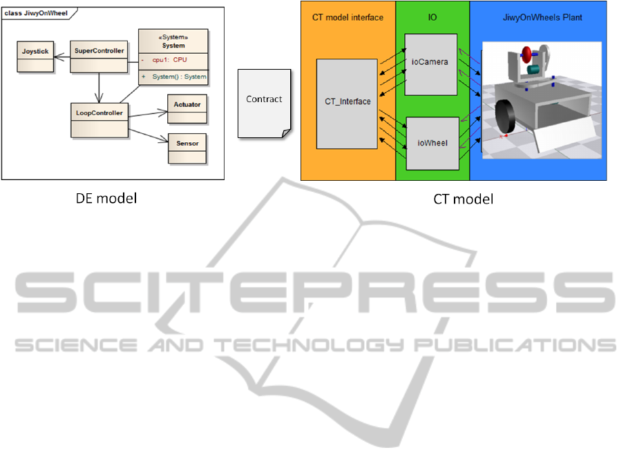
Figure 5: JiwyOnWheels from co-model perspective.
most dominant properties of the system are the move-
ment of the cart with two wheels and the rotation
of the camera mounted on top. All components are
connected to each other by electrical and/or mechan-
ical ports and this behaviour is modelled using bond
graphs. The corresponding control algorithms, e.g.
digital PID controllers in our case, can be designed.
The digital/analog conversion is modelled as A/D
converters with necessary scaling in the IO submodel.
4.2 Migration
When the CT model is competent enough to be used
to construct a co-model, the step of migrating the DT
controller can start. The controller submodel can be
replaced by the CT model interface directly without
changing the IO and plant submodels, see Figure 5.
Signals shared between the DT controller and the IO
submodel are now shared between the CT model in-
terface and IO submodel.
In order to test the performance of the digital con-
troller on different hardware platforms, the DT con-
troller has to be moved from the CT model to DE
model to be deployed on different architectures sup-
ported by the DESTECS tool.
The migration requires converting the DT con-
troller to a time-triggered DE controller using the
VDM formalism. It is implemented as a peri-
odic thread that reads the signals from the sen-
sors and writes to the actuators, shown as the
LoopController class on the left side of Fig-
ure 5. The SampleTime defined in the time-triggered
LoopController has to be the same as set in the CT
simulator to ensure both models are executed at the
same co-simulation time.
In order to describe real-time behaviour in the DE
model, the System class is constructed to handle the
creation of a virtual CPU and the deployment of the
SuperController and LoopController.
In this case study, the DE model is simply de-
signed as an event-triggered supervisory controller, a
time-triggered loop controller and a joystick that gives
steering signals to the robot. More complex DE mod-
els, such as distributed CPU’s running different con-
trollers and connected through a BUS, can be studied
and developed in depth when required.
4.3 Co-model Integration and Result
Finally, the co-model (see Figure 5) is created by
defining the contract in the DESTECS tool and ex-
ecuted using the co-simulation engine. All shared
information between the DE/CT models of JiwyOn-
Wheels is defined in the contract. Figure 6 illustrates
the final co-simulation results in the CT simulator, in
which the steering signals are generated from the DE
model as user inputs from the joystick. The rotation
of the camera and the movement of the cart are con-
trolled by the time-triggered DE controller through
co-simulation. Figure 6(b) shows the trajectory of the
robot movement.
5 CONCLUSIONS
In this paper, we have proposed a structuring mecha-
nism and design process to support the development
of continuous-time intensive ECSs using collabora-
tive modelling and co-simulation techniques. Based
on this approach, complex embedded control systems
can be decomposed into continuous-time (CT) mod-
els and discrete-event (DE) models and further devel-
oped using their own domain-specific languages and
tools. Co-simulation can then be achieved by con-
necting these two models through the co-simulation
contract and DE/CT model interfaces.
Another key feature of our approach is that it al-
lows modellers to design the digital loop controllers
AStructuringMechanismforEmbeddedControlSystemsusingCo-modellingandCo-simulation
135
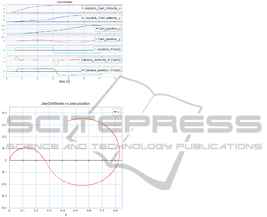
(a) Co-simulation results: the velocity / position of cart
movement; the velocity / position of camera rotation.
(b) JiwyOnWheels simulated position, x versus y.
Figure 6: JiwyOnWheels co-simulation results.
in the CT model, and then migrate them to the DE
model using the time-triggered (TT) DE formalism.
Doing so, the dynamics of the controller can be de-
signed and tuned in the CT domain, and in turn, the
performance of the controller on different hardware
architectures can be tested in the DE domain. In addi-
tion, the same controller/plant models can be reused
easily. We also have described a CT-intensive case
study which demonstrates how to apply this structur-
ing approach and the co-model creation process.
When using collaborative modelling and co-
simulation techniques, many challenges may en-
counter, such as the inconsistency issues caused by
different modelling knowledge across domains or
lack of communications between domain experts.
Our future work will focus on addressing and solving
these challenges and prevent inconsistencies between
domain models while using co-simulation.
ACKNOWLEDGEMENTS
The research leading to these results has received
funding from the European Community’s Seventh
Framework Programme (FP7/2007-2013) under grant
agreement no. 248134 (project DESTECS).
REFERENCES
Bjorner, D. and Jones, C. (1978). The vienna development
method: The meta-language. Lecture Notes in Com-
puter Science.
Broenink, J. F., Groothuis, M. A., Visser, P., and Bezemer,
M. M. (2010). Model-driven robot-software design
using template-based target descriptions. In Kubus,
D., Nilsson, K., and Johansson, R., editors, ICRA
2010 workshop on Innovative Robot Control Architec-
tures for Demanding (Research) Applications, pages
73 – 77. IEEE.
Broenink, J. F., Groothuis, M. A., Visser, P., and Orlic,
B. (2007). A model-driven approach to embedded
control system implementation. In Anderson, J. and
Huntsinger, R., editors, Proceedings of the 2007 West-
ern Multiconference on Computer Simulation WMC
2007, San Diego, pages 137–144, San Diego. SCS,
San Diego.
Controllab Products (2010). The 20-sim dynamic modelling
tool website. http://www.20sim.com.
DESTECS (2010). The DESTECS project website.
http://www.destecs.org.
Fitzgerald, J. S., Larsen, P. G., Pierce, K. G., and Ver-
hoef, M. (2012). A formal approach to collabora-
tive modelling and co-simulation for embedded sys-
tems. Mathematical Structures in Computer Science,
vol(no):1–25. To be published.
Overture Community (2010). The Overture Tool project
website. http://www.overturetool.org.
Paynter, H. (1961). Analysis and design of engineering sys-
tems. MIT Press, Cambridge, MA.
Verhoef, M., Larsen, P., and Hooman, J. (2006). Model-
ing and validating distributed embedded real-time sys-
tems with vdm++. FM2006: Formal Methods.
SIMULTECH2012-2ndInternationalConferenceonSimulationandModelingMethodologies,Technologiesand
Applications
136
