
Particle Filtering for Position based 6DOF Visual Servoing in Industrial
Environments
Aitor Ibarguren, Jos´e Mar´ıa Mart´ınez-Otzeta and I˜naki Maurtua
Fundaci´on Tekniker, Apdo. 44 Otaola 20, 20600 Eibar, Gipuzkoa, Spain
Keywords:
Robotics, Visual Servoing, Particle Filter.
Abstract:
Visual servoing allows the introduction of robotic manipulation in dynamic and uncontrolled environments.
This paper presents a position-based visual servoing algorithm using particle filtering. The objective is the
grasping of objects using the 6 degrees of freedom of the robot manipulator (position and orientation) in non-
automated industrial environments using monocular vision. A particle filter has been added to the position-
based visual servoing algorithm to deal with the different noise sources of those industrial environments
(metallic nature of the objects, dirt or illumination problems). This addition allows dealing with those un-
certainties and being able to recover from errors in the grasping process. Experiments performed in the real
industrial scenario of ROBOFOOT project showed accurate grasping and high level of stability in the visual
servoing process.
1 INTRODUCTION
Traditional industrial robotic applications, like part
placement or spot welding, require precise informa-
tion about the position of the objects to perform their
task. Visual servoing (Weiss et al., 1987; Hutchinson
et al., 1996) can enhance those industrial applications
allowing corrections on the robot trajectories.
Even so, industrial environments raise their own
challenges in the inclusion of visual servoing tech-
niques, especially when the production line is not
completely automated. Dirt, imprecision in the work-
piece placement or changing lighting conditions are
some of the problems that must be tackled in this kind
of environments, introducing uncertainties in the tra-
jectory correction process.
This paper presents a position-based visual servo-
ing algorithm using particle filtering. Based on the
real industrial scenario of ROBOFOOT project, the
paper proposes an algorithm to grasp a workpiece (a
shoe last specifically) from a not constrained work-
shop, correcting the 6 degrees of freedom of the robot
during the visual servoing process.
The paper is organized as follows. In Section 2 the
related work is presented. Section 3 exposes briefly
particle filters. Task specification and configuration is
shown in Section 4. Section 5 is devoted to the pro-
posed approach, while in Section 6 the experimental
results are shown. Finally, Section 7 presents the con-
clusions as well as the future work to be done.
2 RELATED WORK
Several approaches tackle the use of visual servoing
in industrial environments, posing different industrial
scenarios and approaches.
Sung-Hyun et al. (Han et al., 1999) propose an
image-based visual servoing based on stereo vision.
The use of stereo vision allows guiding the robot ma-
nipulator to the desired location without giving such
prior knowledge about the relative distance to the de-
sired location or the model of the object.
Nomura et al. (Nomura and Naito, 2000) describe
a visual servoing system able to track and grasp in-
dustrial parts moving on a conveyor using a 6DOF
robot arm. A hybrid Kalman Filter is also incorpo-
rated to track a moving object stably against visual
data noise. Experiments are also presented, perform-
ing both 3DOF and 6DOF visual servoing.
Finally, Lippiello et al. (Lippiello et al., 2007)
presented visual servoing applications on Industrial
Robotic cells. On their setup, composed of two
industrial robot manipulators equipped with pneu-
matic grippers, vision systems and a belt conveyor, a
position-based visual servoing is proposed. The sys-
tem also uses Extended Kalman Filters (EKF) (Julier
and Uhlmann, 2004) to manage the occlusions during
the multi-arm manipulation.
161
Ibarguren A., Martínez-Otzeta J. and Maurtua I..
Particle Filtering for Position based 6DOF Visual Servoing in Industrial Environments.
DOI: 10.5220/0003965501610166
In Proceedings of the 9th International Conference on Informatics in Control, Automation and Robotics (ICINCO-2012), pages 161-166
ISBN: 978-989-8565-22-8
Copyright
c
2012 SCITEPRESS (Science and Technology Publications, Lda.)
3 PARTICLE FILTER
Particle filters (A. Doucet and Gordon, 2001; Kotecha
and Djuric, 2003), also known as sequential Monte
Carlo methods (SMC), are sequential estimation tech-
niques that allow estimating unknown states x
t
from a
collection of observationsz
1:t
= {z
1
,...,z
t
}. The state-
space model is usually described by state transition
and measurement equations
x
t
= f
t
(x
t−1
,v
t−1
) (1)
z
t
= g
t
(x
t
,u
t
) (2)
where f and g are the state evolution and observa-
tion model functions respectively and v
t
and u
t
denote
the process and observation noise respectively.
Based on the previous equations, particle filters
allow approximating the posterior density (PDF) by
means of a set of particles {x
(i)
t
}
i=1,...,n
using equa-
tion
p(x
t
|z
1:t
) =
N
∑
i=1
ω
(i)
t
δ(x
t
− x
(i)
t
) (3)
where each particle x
(i)
t
has an importance weight
ω
(i)
t
associated and δ is the Kronecker delta. These
weights are computed following equation
ω
(i)
t
= ω
(i)
t−1
p(z
t
|x
(i)
t
)p(x
(i)
t
|x
(i)
t−1
)
q(x
(i)
t
|x
(i)
0:t−1
,z
0:t
)
(4)
where p(z
t
|x
(i)
t
) is the likehood function of the
measurements z
t
and q(x
(i)
t
|x
(i)
0:t−1
,z
0:t
) is the proposal
density function.
Based on the previously presented equations the
particle set evolves along time, changing the weights
of the particles and resampling them in terms of the
observations.
4 TASK SPECIFICATION AND
CONFIGURATION
Based on the needs of ROBOFOOT project, an object
grasping task has been designed using real specifica-
tions of footwear workshops. The grasping scenario
has been specified as:
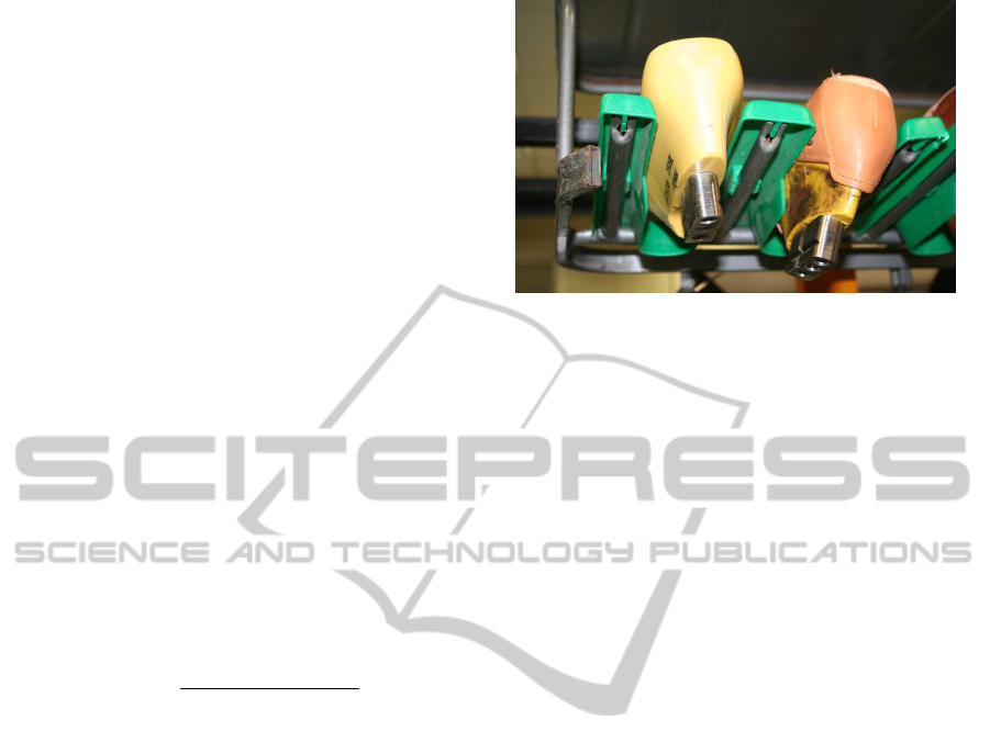
• Lasts, material with the shape of a foot used to
build shoes, are the object to be grasped. An iron
piece (grasping device) has been added to lasts
to allow a precise and stiff grasping, see Fig. 1,
as well as to protect the leather during the grasp-
ing process. Those grasping devices will be the
objects to be identified during the visual servoing
process.
Figure 1: Lasts with the grasping device on the trolley.
• Lasts are carried in specific trolleys mounted on a
manovia. The trolleys are designed to allow the
placement of lasts of different shapes and sizes.
Lasts are placed in the trolley by human operators.
Due to those previous facts it is not possible to
know the pose of the last in the trolley, as seen in
Fig. 1.
• A 6DOF robot arm with a gripper and a camera
and lighting system mounted on the end-effector
with an eye-in-hand configuration.
• Based on the design of the gripper and the grasp-
ing device, the grasping process requires a preci-
sion of around a millimeter and 1-2 degrees on
each axis to grasp the last smoothly. In the same
way the maneuver should take no more than 5-6
seconds.
Based on this scenario, the initial set-up of the sys-
tem has raised some problems related with the pose
estimation of the grasping device:
• Illumination is a key aspect in a vision system. In
this industrial scenario is complicated to place a
suitable external illumination, that is why it was
decided to put a specific lighting system on the
gripper. Even so, the metallic nature of the grasp-
ing device makes it difficult to get a good image
due to the brightness, reflection and the impossi-
bility of lighting all the image properly.
• Some of the tasks to be performed by both the hu-
man operators and robots involve the use of ink,
wax or generate dust (roughing process). This dirt
can be adhered to the grasping device, complicat-
ing the visual servoing process.
Those previous points will make it difficult to ac-
quire clear images of the grasping device, adding un-
certainties to the 6DOF pose estimation that will be
the base of the visual servoing process.
ICINCO2012-9thInternationalConferenceonInformaticsinControl,AutomationandRobotics
162

5 PROPOSED APPROACH
Taking into account the needed precision, which im-
plies a high resolution camera, and the demanding im-
age processing due to the unstable conditions of the
image, a dynamic look-and-move approach has been
adopted. A particle filter has also been added to the
system to manage the uncertainties of the vision sys-
tem.
Next lines will describe the general structure of
the system, as well as the vision module, pose estima-
tion, the particle filter and the grasping algorithm.
5.1 System Modeling and Architecture
In the described scenario, the space can be repre-
sented by P ∈ ℜ
6
, a set of three positions and three
orientations, where P = [x,y, z, α,β, γ]
T
. In the same
way, this scenario will be composed of two different
frames, the robot frame r and the camera frame c.
Given those two frames, the homogeneous transfor-
mation matrix, denoted by
r
T
c
, transforms poses from
frame c to frame r as:
P
r
=
r
T
c
P
c
(5)
The error of the positioning task involved in the
grasping process is represented by vector E ∈ ℜ
6
which represents the difference between the pose of
the object P
r
o
in the robot frame and the pose of the
end-effector P
r
e
in the robot frame (6). The grasping
process can be seen as a minimization of this error
that will be fulfilled when |E| = 0.
E = P
r
e
− P
r
o
=
x
r
e
− x
r
o
y
r
e
− y
r
o
z
r
e
− z
r
o
α
r
e
− α
r
o
β
r
e
− β
r
o
γ
r
e
− γ
r
o
(6)
For pose estimation, position-based visual servo-
ing systems extract features from the acquired images
and estimate the pose of the object P
r
o
and perform
the corrections. Even so, the described scenario intro-
duces uncertainties in the feature extraction step (il-
lumination, metallic workpiece...), introducing errors
in the pose estimation. To deal with this problem, the
use of a particle filter is proposed. From each image, a
set of n feature vectors F
i
= { f
1
, f
2
,..., f
m
}
i=1...n
will
be extracted for the pose estimation, each of them re-
lated with a specific image analysis procedure. Each
of those n vectors will be a hypothesis of the values
of the m features used for the pose estimation, as it
will not be possible to have a unique feature vector
extracted from each image due to the uncertainties in
the image.
From each feature vector F
i
, P
c
o
i
and P
r
o
i
will be
calculated,
P
c
o
i
= PE(F
i
) (7)
P
r
o
i
=
r
T
c
P
c
o
i
(8)
where P
c
o
i
is the i-th hypothesis of the pose of the
object in the camera frame, P
r
o
i
is the i-th hypothesis
of the pose of the object in the robot frame and pose
estimation function PE is the function that relates a
set of features with a pose of the object in the camera
frame.
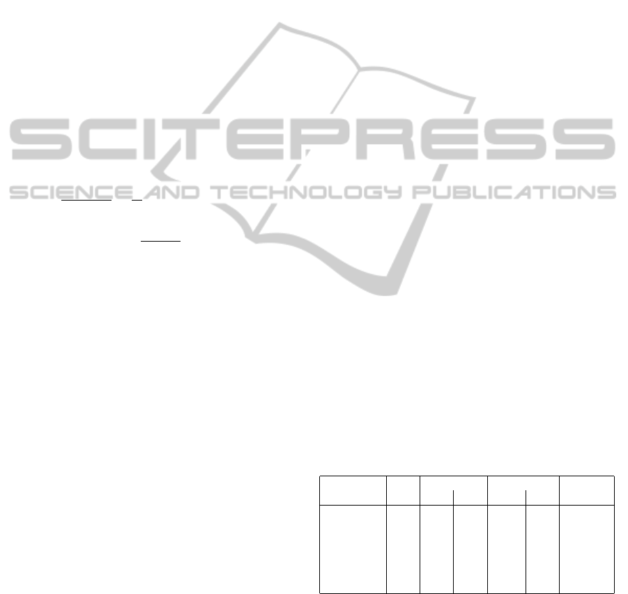
Figure 2: Dynamic position based look-and-move structure
with particle filter.
Those n poses, P
r
o
i=1..n
will be the observations of
the particle filter, which will output the final pose es-
timation of the object in the robot frame P
r
o
. This final
pose will be used to calculate the error E between the
object and the end-effector, used to calculate the next
robot movement. Fig. 2 shows the structure of the
proposed Visual Servoing system.
Next lines will describe the feature extraction,
pose estimation, particle filtering and grasping algo-
rithm of the grasping process.
5.2 Feature Extraction
As stated before, one of the challenges of the pre-
sented scenario is the feature extraction for pose es-
timation. The metallic nature of the grasping device
and the illumination problems make it difficult to de-
tect the different features (edges, corners, holes) pre-
cisely. Taking also into account the perspective of the
camera through the grasping process, the image fea-
tures used for pose estimation, shown in Fig. 3, are:
• The center of the three holes (1, 2, 3) of the grasp-
ing device. Only the pixels of the center of the
holes are included, excluding the size and dimen-
sions of the holes, due to the difficulties of extract-
ing their contour precisely.
• The inclination of the left edge (4) of the grasping
device.
To detect those image features different thresh-
olds, edge detection algorithms and filters are used.
Even so, in some images it is not possible to deter-
mine the exact position of the three holes’ centres as
ParticleFilteringforPositionbased6DOFVisualServoinginIndustrialEnvironments
163
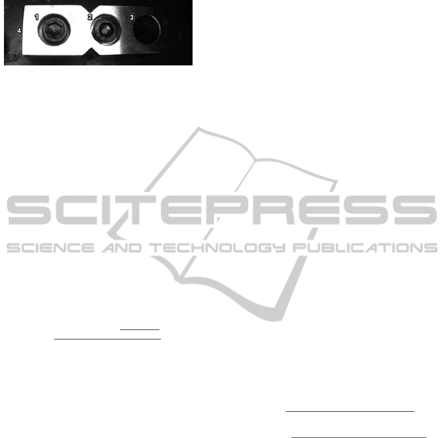
Figure 3: Visual features for pose estimation.
there are variouspossible circular shapes in each posi-
tion (ex. the inner screw, outer circle and dirt around
it). In those cases it is not possible to define a uni-
versal rule to determine which the real contour of the
holes is. To overcome this problem, this approach
proposes to use all those possible centers of the three
holes (left, central and right), creating a set of hypoth-
esis that will be used for pose estimation.
Once the centers of the holes and the left edge are
detected, a feature vector will be calculated for each
hypothesis as:
F
i
= {c
2
,d
12
,d
13
,d
23
,φ
12
,φ
13
,φ
23
,φ
edge
,λ} (9)
where c
2
is the coordinate in pixels of the central
hole, d
ij
is the distance in pixels between the holes i
and j, φ
ij
is the angle between the holes i and j, φ
edge
is the angle of the left side of the grasping device and
λ is a coefficient that measures the noise (quality) of
the hypothesis based on the similitude of the circular
shapes and their alignment and calculated as
λ =
C
v
(p
1
, p
2
, p
3
) +
|φ
12
−φ
13
|+1
|φ
13
|+1
Min(r
xy
1
,r
xy
2
,r
xy
3
)
(10)
where p
i
is the perimeter of the ith hole, C
v
is the
coefficient of variation of the perimeters and r
xy
i
is the
xy axis ratio of the bounding box of the ith hole.
Those are the features that will be used to estimate
the pose of the workpiece.
5.3 Pose Estimation
Once the image is analyzed and the features are ex-
tracted, the pose of the object in the camera frame for
each of the possible hypothesis are calculated as
P
c
o
i
= [x
i
,y
i
,z
i
,α
i
,β
i
,γ
i
]
T
= PE(F
i
) (11)
where each position and orientation is a quadratic
function based on some of the features. The coeffi-
cients of the quadratic functions are omitted from the
paper as they are related to the size of the grasping
device and the aberration of the lens.
PE(F
i
) =
x
i
= f(c
2
,d
12
,d
13
,d
23
)
y
i
= g(c
2
,d
12
,d
13
,d
23
)
z
i
= h(d
12
,d
13
,d
23
)
α
i
= j(φ
12
,φ
13
,φ
23
)
β
i
= k(d
12
,d
23
)
γ
i
= l(φ
edge
)
(12)
Once the hypothetical poses of the object in the
camera frame P
c
o
i
are estimated, the poses in the robot
frame P
r
o
i
are calculated using the homogeneoustrans-
formation matrix
r
T
c
. Those hypothesis will be the
observations of the particle filter.
5.4 Particle Filter
Once the possible hypothesis are calculated it is nec-
essary to merge and fuse this information to perform
the grasping process. To this end a particle filter is
proposed, as it fits in this kind of non-gaussian prob-
lem.
Focusing on the posed problem, the state in time
t will be defined as a pose of the object in the robot
frame
X
t
= [x
t
,y
t
,z
t
,α
t
,β
t
,γ
t
]
T
(13)
As it is not possible to model the pose estimation
error a priori, the state transition is defined as
X
t
= X
t−1
+V
t−1
(14)
where X
t−1
is the previous state vector and V
t−1
is
the process noise.
The observation, on the other hand, is defined by
a set of hypothetical poses of the object in the robot
frame
Z
t
= P
r
o
i=1..n
(15)
So based on this information source each particle
will be defined by a probability P(X
t
|Z
t
).
5.4.1 Probability
To calculate the probability of a state given an ob-
servation, initially the distance between the poses is
calculated as
distPos
i
=
q
(x
t
− x
i
)
2
+ (y
t
− y
i
)
2
+ (z
t
− z
i
)
2
(16)
distAng
i
=
q
(α
t
− α
i
)
2
+ (β
t
− β
i
)
2
+ (γ
t
− γ
i
)
2
(17)
where distPos
i
is the Euclidean distance between
x, y and z positions of the state t and the ith hypoth-
esis and distAng
i
is the Euclidean distance between
the α, β and γ orientations of the state t and the ith
hypothesis.
P(X
t
|Z
t
) =
n
∏
i=1
e
−distPos
i
·distAng
i
·(1+λ
i
)
(18)
Based on this distance, the probability of the state
is calculated as the product of the exponential of the
distances of all the hypothesis ponderated by the λ
i
noise coefficient.
ICINCO2012-9thInternationalConferenceonInformaticsinControl,AutomationandRobotics
164
5.4.2 Particle Filtering Procedure
Finally the procedure of the particle filter is given as:
• 1: Find the grasping device in the initial image
and initialise N particles X
(i)
0
with the differenthy-
pothesis randomly, where w
(i)
0
= 1/N
• 2: if ESS < threshold (Effective Sample Size),
draw N samples with selection with replacement
• 3: Predict x
(i)
t
= x
(i)
t−1
+ v
t−1
• 4: Replace the particles with the lowest weight by
the new hypothesis found in the image
• 5: Update importance weights w
(i)
t
=
w
(i)
t−1
P(X
t
|Z
t
)
• 6: Normalize weights w
(i
′
)
t
= w
(i)
t
/
∑
N
j=1
w
( j)
t
• 7: Set t = t + 1, goto Step 2
In this procedure EES (Liu et al., 2000) (Effective
Sample Size) is calculated as
cv
2
t
=
var(w
(i)
t
)
E
2
(w
(i)
t
)
=
1
N
N
∑
i=1
(Nw
(i)
t
− 1)
2
(19)
ESS
t
=
N
1+ cv
2
t
(20)
where N is the number of particles and w
(i)
t
is the
weight of particle i in time t. The fourth step has been
added to allow a fast convergence.
Based on this discrete approximation of the poste-
rior probability, the object is tracked along the grasp-
ing procedure.
5.5 Grasping Algorithm
The feature extraction step has shown that the best
images are acquired when camera is perpendicular to
the grasping device and the end-effector to a 30mm
distance, E = [0,0, 30,0,0,0]
T
, as it solves in part
the illumination problems. Taking it into account the
grasping algorithm will try to minimize the error until
this value is reached, adding an small tolerance of ±1
mm in position and ±1.5
◦
in orientation to avoid an
infinite loop. Once this error is reached the robot will
make a final approach in just one axis and perform the
grasping.
6 EXPERIMENTAL RESULTS
To test the performance of the proposed approach an
experiment has been designed in order to measure its
suitability. Those are the specifications of the experi-
ment:
• Six different particle filter configurations have
been set-up, mixing different state estimation
methods and number of particles. Specifically the
estate estimation methods are:
– Best particle (the one with maximum weight)
– Robust mean with the 3 particles with maxi-
mum weight (denoted as R.M. 3)
– Robust mean with the 5 particles with maxi-
mum weight (denoted as R.M. 5)
• For each configuration, 250 repetitions have been
performed using different shoes and grasping de-
vices. Most of the grasping devices have been
dirtied up to include variety and simulate real
conditions. Due to the structure of the manovia,
the grasping device will be placed in a space of
200x100x200mm (depending on the shoe and its
placement) and with a rotation of ±15
◦
in each
axis.
• The grasping process will fail if does not achieve
to pick up the shoe. There are two reasons for
this fail, the grasping device has not been found in
the initial image (ex. not well illuminated due to
its orientation) or a wrong pose estimation which
leads to movement that leaves the grasping de-
vices out of the scope of the camera.
TABLE 1 shows the results of the experiment. The
first column describes the number of particles and the
estimation method, the second one the success rate,
third and fourth columns show the mean (µ) and the
standard deviation (σ) of the grasping time in sec-
onds, fifth and sixth columns the mean (µ) and the
standard deviation (σ) of the number of movements
required to grasp the shoe and finally the last column
shows the time required to process each cycle of the
particle filter in milliseconds.
Table 1: Results of the experiment.
Time (s) Mov.
% µ σ µ σ ms/image
50 - Best 96.4 4.84 1.79 10.39 4.45 127.53
100 - Best 95.6 4.94 2.03 10.41 5.34 133.50
50 - R.M. 3 97.2 4.96 1.85 10.36 4.99 133.79
100 - R.M. 3 98 4.98 1.71 10.27 4.68 136.71
50 - R.M. 5 99.6 4.78 1.94 10.25 5.05 123.03
100 - R.M. 5 99.2 4.69 1.65 9.89 4.14 127.94
Results show a better performance of the system
using the robust mean estimation method with 5 par-
ticles, both in success rate and in grasping time. In
the case of the success rate, in all the configurations
a part of the fails were related with the search of the
grasping device in the initial image (more or less the
same quantity for each configuration, around a 1-2%).
ParticleFilteringforPositionbased6DOFVisualServoinginIndustrialEnvironments
165

In the same way, it seems that the addition of more
particles does not help to improve the success rates
although it does not increase significantly the process-
ing time of each visual servoing iteration.
7 CONCLUSIONS AND FUTURE
WORK
This paper presents a dynamic position-based look-
and-move architecture to perform visual servoing
with 6DOF in industrial environments. This kind
of environments usually suffers from unstable condi-
tions like changing lighting condition or dirt, intro-
ducing uncertainties in the visual servoing process.
To overcomethe above mentioned problem, this paper
proposes the use of a particle filter to manage multiple
hypothesis of the poses of the workpiece to grasp.
The results show a high success rate of the grasp-
ing system, reaching around a 99% of success in the
different experiments performed. The use of particle
filtering allows the use and fuse various hypothesis,
overcoming the noise problems of the presented sce-
nario. The system also performs the grasping process
in a suitable time, increasing fewprocessing time with
the addition of the particle filter.
As further work, there are two interesting paths
to follow. On one hand, test this approach in simi-
lar scenarios (different workpiece, environment, noise
source...) to test its suitability. On the other hand, one
or more sensors could be attached to the end-effector
as new data sources, using the particle filter to fuse
the information received from the different sources as
done in different robotic applications.
ACKNOWLEDGEMENTS
This work has been performed within the scope of the
project ”ROBOFOOT: Smart robotics for high added
value footwear industry ”. ROBOFOOT is a Small
or Medium-scale focused research project supported
by the European Commission in the 7th Framework
Programme (260159). For further information see
http://www.robofoot.eu
REFERENCES
A. Doucet, N. De Freitas, N. and Gordon, N. (2001). Se-
quential Monte Carlo methods in practice. Springer-
Verlag.
Han, S.-H., Seo, W., Yoon, K., and Lee, M.-H. (1999). Real-
time control of an industrial robot using image-based
visual servoing. In Intelligent Robots and Systems,
1999. IROS ’99. Proceedings. 1999 IEEE/RSJ Inter-
national Conference on, volume 3, pages 1762 –1767
vol.3.
Hutchinson, S., Hager, G., and Corke, P. (1996). A tuto-
rial on visual servo control. Robotics and Automation,
IEEE Transactions on, 12(5):651 –670.
Julier, S. and Uhlmann, J. (2004). Unscented filtering
and nonlinear estimation. Proceedings of the IEEE,
92(3):401 – 422.
Kotecha, J. and Djuric, P. (2003). Gaussian particle fil-
tering. Signal Processing, IEEE Transactions on,
51(10):2592 – 2601.
Lippiello, V., Siciliano, B., and Villani, L. (2007). Position-
based visual servoing in industrial multirobot cells us-
ing a hybrid camera configuration. Robotics, IEEE
Transactions on, 23(1):73 –86.
Liu, J., Chen, R., and Logvinenko, T. (2000). A theoretical
framework for sequential importance sampling and re-
sampling. Sequential Monte Carlo Methods in Prac-
tice, pages 1–24.
Nomura, H. and Naito, T. (2000). Integrated visual servo-
ing system to grasp industrial parts moving on con-
veyer by controlling 6dof arm. In Systems, Man, and
Cybernetics, 2000 IEEE International Conference on,
volume 3, pages 1768 –1775 vol.3.
Weiss, L., Sanderson, A. C., and Neuman, C. P. (1987).
Dynamic sensor-based control of robots with visual
feedback. IEEE Journal on Robotics and Automation,
RA-3(5).
ICINCO2012-9thInternationalConferenceonInformaticsinControl,AutomationandRobotics
166
