
DESIGN OF A COMPRESSIVE REMOTE IMAGING SYSTEM
COMPENSATING A HIGHLY LIGHTWEIGHT ENCODING
WITH A REFINED DECODING SCHEME
George Tzagkarakis
1
, Arnaud Woiselle
2
, Panagiotis Tsakalides
3
and Jean-Luc Starck
1
1
CEA/DSM, SEDI-SAp, Service d’Astrophysique, Centre de Saclay, F-91191 Gif-Sur-Yvette, France
2
Sagem D
´
efense S
´
ecurit
´
e, 95100 Argenteuil, France
3
Institute of Computer Science (ICS), Foundation for Research & Technology - Hellas (FORTH), Crete, Greece
Keywords:
Compressive Video Sensing, Lightweight Remote Imaging Systems.
Abstract:
Lightweight remote imaging systems have been increasingly used in surveillance and reconnaissance. Never-
theless, the limited power, processing and bandwidth resources is a major issue for the existing solutions, not
well addressed by the standard video compression techniques. On the one hand, the MPEGx family achieves
a balance between the reconstruction quality and the required bit-rate by exploiting potential intra- and inter-
frame redundancies at the encoder, but at the cost of increased memory and processing demands. On the other
hand, the M-JPEG approach consists of a computationally efficient encoding process, with the drawback of
resulting in much higher bit-rates. In this paper, we cope with the growing compression ratios, required for all
remote imaging applications, by exploiting the inherent property of compressive sensing (CS), acting simul-
taneously as a sensing and compression framework. The proposed compressive video sensing (CVS) system
incorporates the advantages of a very simple CS-based encoding process, while putting the main computa-
tional burden at the decoder combining the efficiency of a motion compensation procedure for the extraction
of inter-frame correlations, along with an additional super-resolution step to enhance the quality of recon-
structed frames. The experimental results reveal a significant improvement of the reconstruction quality when
compared with M-JPEG, at equal or even lower bit-rates.
1 INTRODUCTION
Modern lightweight digital sensing devices with high-
resolution signal acquisition, processing, and commu-
nication capabilities are largely based on the well-
established Shannon and Nyquist theories. Managing
ever increasing amounts of data remains a challenging
task, especially for practical applications, where de-
vices with limited processing, storage, and bandwidth
resources are involved. Moreover, the increasing de-
mand for higher acquisition rates and even improved
resolution is placing a significant burden on the exist-
ing hardware architectures.
Video acquisition and processing posses a cen-
tral role in numerous emerging applications, such as
surveillance and reconnaissance, both at the civil-
ian and battlegroup levels, robot navigation, remote
surgery and entertainment. Most video surveillance
systems monitor actively and remotely an area of in-
terest through video streaming, or passively by storing
the captured video for future use. In addition, recent
technological advances enable the design of low-
cost devices that incorporate enhanced multimodal
sensing, processing, and communication capabilities.
At the same time, the limited resources of the
compression hardware is still a major bottleneck for
the design of lightweight remote imaging systems,
where very low data rates are strongly required to
maximize the lifetime of the system (e.g., in the case
of a terrestrial sensor network), while preserving an
increased performance. To cope with such growing
compression ratios existing video compression tech-
niques, such as the MPEGx profiles and the Motion
JPEG (M-JPEG) scheme, may result in poor image
quality.
The framework of compressive sensing
(CS) (Cand
´
es et al., 2006), acting simultane-
ously as a sensing and compression protocol, could
be exploited in the design of low-complexity on-
board remote imaging devices with reduced power
46
Tzagkarakis G., Woiselle A., Tsakalides P. and Starck J..
DESIGN OF A COMPRESSIVE REMOTE IMAGING SYSTEM COMPENSATING A HIGHLY LIGHTWEIGHT ENCODING WITH A REFINED
DECODING SCHEME.
DOI: 10.5220/0003842400460055
In Proceedings of the International Conference on Computer Vision Theory and Applications (VISAPP-2012), pages 46-55
ISBN: 978-989-8565-03-7
Copyright
c
2012 SCITEPRESS (Science and Technology Publications, Lda.)

and processing requirements. Its simplicity stems
from the linearity of the associated non-adaptive
incoherent projections, which are employed for the
representation and reconstruction of sparse signals.
Recently, the framework of compressive video
sensing (CVS) was introduced as a natural extension
proposing distinct approaches for video acquisition
using a reduced amount of data, while maintaining a
similar reconstruction performance when compared
to standard video compression techniques.
Existing CVS approaches perform separate
encoding of each frame, based on a non-overlapping
block splitting to reduce the storage and computa-
tional costs, by combining full sampling of reference
frames with CS applied on non-reference frames.
Then, at the decoder, the reconstruction is performed
separately (Stankovi
´
c et al., 2008), or jointly by either
considering a joint sparsity model as in (Kang and
Lu, 2009) or by designing an adaptive sparsifying
basis using neighboring blocks in previously recon-
structed frames (Do et al., 2009; Prades-Nebot et al.,
2009). The major drawbacks are that, since potential
spatio-temporal redundancies are not removed at the
encoder, the corresponding CVS methods usually
result in increased bit-rates, while also being sensitive
to the propagation of reconstruction errors along the
sequence in the case of joint decoding.
The efficiency of typical video compression
standards, such as the MPEGx, in achieving a good
tradeoff between the reconstruction quality and
the associated bit-rates, is primarily based on the
capability of removing potential spatio-temporal
redundancies by means of intra-frame transform
coding and inter-frame motion prediction. However,
an encoder with increased memory and processing
resources is required, which may be prohibitive in
a lightweight remote imaging system. On the other
hand, the use of M-JPEG, which is an intra-frame-
only video compression scheme, has the advantage of
imposing significantly lower processing and memory
requirements on the hardware, but at the cost of
increasing significantly the required bit-rate, which is
restrictive in the case of limited bandwidth.
In the present work, we address the drawbacks of
the previous CVS methods, as well as the limitations
of MPEGx and M-JPEG compression techniques, by
introducing a CVS scheme which could be integrated
in onboard video sensing devices with restricted
resources. In particular, the proposed CVS method
combines a simplified encoding process by embed-
ding a CS module in an M-JPEG-like encoder, along
with a refinement phase based on inter-frame predic-
tion at the decoder (as opposed to MPEGx, where
the prediction errors are formed at the encoder). The
idea of transferring the computational burden of the
motion estimation and compensation processes at the
decoder was also appeared in (Jung and Ye, 2010)
in the framework of dynamic magnetic resonance
imaging, where an auxiliary sequence of residual
frames was generated at the decoder recursively
using a set of fully-sampled reference frames in
conjunction with the low-resolution dynamic frames.
Moreover, the required bit-rate of our proposed
encoder can be further decreased by downsampling
the non-reference frames, followed by an additional
super-resolution step at the decoder to restore the
reconstructed frames in their original resolution.
The use of super-resolution as a tool to resize the
frames in their original dimension is motivated by
recent works on sparse representation-based image
super-resolution via dictionary learning (Freeman
et al., 2002; Yang et al., 2008; Wang et al., 2011;
Zhang et al., 2011), where it has been shown that
a super-resolution method results in images with
superior quality when compared to the commonly
used 2-dimensional interpolation schemes (e.g.,
bilinear, bicubic, spline).
The paper is organized as follows: in Section 2,
the model for the compressed measurements acqui-
sition is introduced. Section 3 describes in detail
the proposed CVS architecture, while a performance
evaluation is carried out in Section 4. Finally,
conclusions and further extensions are outlined in
Section 5.
2 CS MEASUREMENTS MODEL
In the following, we consider for convenience the case
of square N × N frames, although the proposed ap-
proach is extended straightforwardly in the general
non-square case. The main disadvantage when we
deal with a remote imaging device with limited capa-
bilities, as mentioned in Section 1, is the high memory
and computational expense when we operate at high
resolutions. This drawback can be alleviated by pro-
ceeding in a block-wise fashion. More specifically, in
the proposed CVS system, each frame is divided into
equally sized B × B non-overlapping blocks. Then, a
measurement vector g
j
, j = 1,...,n
B
, is generated for
each one of the n
B
blocks via a simple linear model as
follows,
g
j
= Φ
j
x
j
, (1)
where Φ
j
∈ R
M×B
2
is a suitable measurement ma-
trix (M B
2
) and x
j
∈ R
B
2
denotes the j-th block
of frame x, reshaped as a column vector. Although,
in general, a distinct measurement matrix can be as-
DESIGN OF A COMPRESSIVE REMOTE IMAGING SYSTEM COMPENSATING A HIGHLY LIGHTWEIGHT
ENCODING WITH A REFINED DECODING SCHEME
47

signed to each block, in the following we apply the
same measurement matrix on each block for simplic-
ity, that is, Φ
j
≡ Φ, j = 1,. .. ,n
B
. Thus, the measure-
ment vector g
j
provides directly a compressed repre-
sentation of the original space-domain block x
j
.
Common choices for the measurement matrix Φ
are random matrices with independent and identically
distributed (i.i.d.) Gaussian or Bernoulli entries. In
a remote imaging system some additional require-
ments should be posed on the choice of Φ, such as
the use of a minimal number of compressed measure-
ments, and the fast and memory efficient computation
along with a “hardware-friendly” implementation. A
class of matrices satisfying these requirements, the
so-called structurally random matrices, was intro-
duced recently (Do et al., 2008). The block Walsh-
Hadamard (BWHT) operator is a typical member of
this class and will be used in the proposed design.
If the j-th block is compressible or has a K-sparse
representation in an appropriate sparsifying transform
domain, and if the measurement matrix along with
the sparsifying dictionary satisfy a sufficient inco-
herence condition, then x
j
can be recovered from
M & O(2K logB) measurements by solving the fol-
lowing optimization problem,
min
w
j
kw
j
k
1
s.t. g
j
= ΦΨ
−1
s
w
j
, (2)
where Ψ
s
is an appropriate sparsifying transforma-
tion, such as an orthonormal basis (e.g., discrete
cosine transform (DCT), discrete wavelet transform
(DWT)) or an overcomplete dictionary (e.g., undec-
imated DWT (UDWT)), and w
j
is the transform-
domain sparse representation of x
j
in Ψ
s
. If Ψ
s
is
different than the identity, then the reconstruction of
the j-th block is first performed in the transform do-
main,
ˆ
w
j
, followed by an inversion to obtain the fi-
nal space-domain estimate,
ˆ
x
j
= Ψ
−1
s
ˆ
w
j
, otherwise
the space-domain solution is obtained directly, that is,
ˆ
x
j
≡
ˆ
w
j
. In the subsequent experimental evaluations,
and in order to be consistent with the M-JPEG com-
pression scheme to which we compare, the DCT is
used as the sparsifying dictionary.
The next section analyzes in detail the structural
components of the proposed CVS architecture, start-
ing with a brief overview of M-JPEG. The main rea-
son for choosing the M-JPEG as a benchmark method
for comparison, and not a member of the MPEGx
family, stems from the fact that both M-JPEG and
our approach are based on a very simplified encoder,
working directly in the original frame-domain, with-
out exploiting inter-frame redundancies via motion
compensation, as in MPEGx, which is proven to be
the step with the highest memory and power con-
sumption. We emphasize again that our goal is to
build a CVS system with a lightweight encoder, so as
to satisfy the constraints of a remote imaging system.
On the other hand, we consider that the reconstruction
takes place at a base station, where increased memory
and computational resources are available in practice.
3 PROPOSED CVS SYSTEM
In the following, the main building blocks of the pro-
posed CVS system are described in detail. Before
proceeding, we start with a brief overview of the basic
structure of M-JPEG, to which we compare in the rest
of the paper.
3.1 Overview of M-JPEG
M-JPEG is a lossy intra-frame compression scheme.
In particular, each frame of the video sequence is
transformed in the DCT domain, followed by the
quantization of the corresponding DCT coefficients
using a perceptual model based loosely on the human
visual system. This model discards high-frequency
information since its changes are almost unperceiv-
able to the human eye. The quantized coefficients are
then encoded losslessly and packed into the output
bit-stream. The building blocks of an M-JPEG sys-
tem are shown in Fig. 1
As a purely intra-frame-only compression
scheme, the performance of M-JPEG is related
directly to the spatial complexity of each video
frame. In particular, frames that contain large smooth
transitions or monotone surfaces are compressed
well, and are more likely to preserve their original
details with few visible compression artifacts. On
the contrary, frames containing structures such as
complex textures, fine curves and lines are prone
to exhibit artifacts such as ringing, smudging, and
macroblocking. An advantage of M-JPEG is that it is
insensitive to the motion complexity.
Since the video frames are compressed separately,
M-JPEG imposes lower processing and memory re-
quirements on the hardware devices, when compared
with MPEGx. This justifies its widespread use in digi-
tal and IP cameras, in HDTV media players and game
consoles. Although the bit-rate of M-JPEG is lower
than that of an uncompressed video, however, it is
much higher than the bit-rate of a video which is com-
pressed using inter-frame motion compensation, such
as the MPEGx does.
Motivated by the above, the proposed CVS en-
coder is designed with the goal of preserving the sim-
ple structure of an M-JPEG-based encoder, with the
VISAPP 2012 - International Conference on Computer Vision Theory and Applications
48

Figure 1: Structure of an M-JPEG system.
power of CS to represent the information content of a
given signal, characterized by a sparse representation
in an appropriate transform domain, using a highly
reduced set of compressed measurements.
3.2 CVS Architecture
3.2.1 Encoder
The need to satisfy the constraints of a lightweight
remote imaging system motivated the design of a
CVS encoder which combines the simplicity of the
M-JPEG approach, with the efficiency of CS to rep-
resent the salient information content of a given sig-
nal via a low-dimensional set of compressed measure-
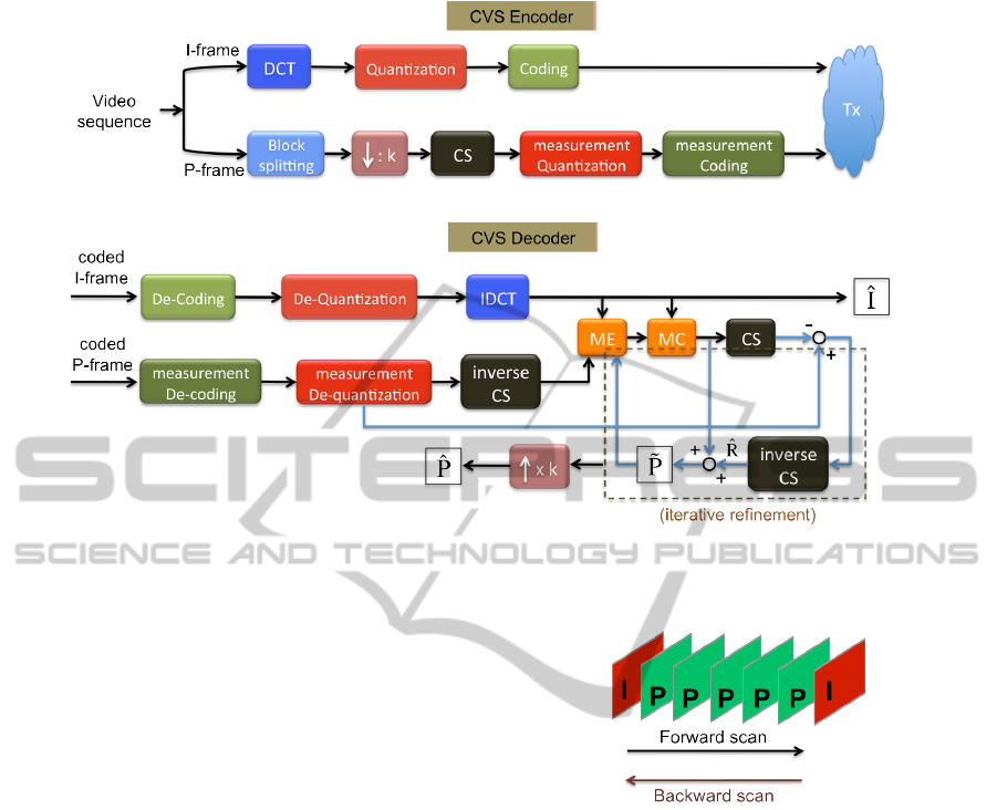
ments. Fig. 2(a) shows the building components of
the proposed CVS encoder. More specifically, the in-
put video sequence is divided into successive groups
of pictures (GOPs) of the form I PP .. . P I, where I
corresponds to a reference frame (I-frame) and P to
a non-reference frame (P-frame). The I-frames are
fully sampled and compressed using JPEG, that is,
the DCT is applied on non-overlapping 8 × 8 blocks
of the original frame, followed by quantization and
encoding of the transform coefficients.
Without loss of generality, in the following we
will focus on the case of grayscale videos. The quan-
tization of the DCT coefficients corresponding to the
luminance component is performed as follows,
D
q
(m,n) = round
D(m,n)
S · Q(m,n)
, (3)
where D ∈ R
8×8
denotes the matrix of DCT coef-
ficients for an 8 × 8 block of the original frame,
D
q
∈ R
8×8
is the corresponding matrix of the quan-
tized coefficients, S is a scaling factor varying from 1
(high image quality) to 100 (low image quality), and
Q ∈ R
8×8
is the following quantization table,
Q =
8 16 19 22 26 27 29 34
16 16 22 24 27 29 34 37
19 22 26 27 29 34 34 38
22 22 26 27 29 34 37 40
22 26 27 29 32 35 40 48
26 27 29 32 35 40 48 58
26 27 29 34 38 46 56 69
27 29 35 38 46 56 69 83
(4)
Then, the quantized DCT coefficients are encoded
losslessly using an improved Huffman coding scheme
using recursive splitting (Skretting et al., 1999).
In contrast to the full sampling of the I-frames,
a CS measurements acquisition process is applied on
the P-frames. In particular, a compressed measure-
ment vector is generated for each B × B block of a
P-frame. A satisfactory tradeoff between the compu-
tational complexity at the encoder and the reconstruc-
tion performance at the decoder is achieved for blocks
of size 16 × 16 and 32 × 32. A further reduction of
the transmission bit-rate can be attained by downsam-
pling a P-frame prior to the measurements acquisi-
tion, that is, the measurement model given by (1) is
generalized as follows,
g
j
= ΦD {x
j
} , (5)
where D{·} denotes the downsampling operator. In
the subsequent evaluations we will consider that each
P-frame is downsampled by a factor of 2. Then a uni-
form scalar quantization is applied on the CS mea-
surements, followed by Huffman coding.
From the above it can be seen that the parame-
ters which affect the performance of the encoder are:
i) the size of a GOP, ii) the scaling factor S (for the
I-frames) and the number of quantization levels (for
the P-frames), and iii) the sampling rate M/B
2
, where
M is the number of compressed measurements for a
block of size B × B. More specifically, the size of a
GOP is related to the motion complexity of a video se-
quence, and it should decrease (or equivalently, more
fully-sampled I-frames must be inserted) for videos
with highly varying content. Of course, as the number
of the fully-sampled I-frames increases, the required
bit-rate also increases. Regarding the quantization of
the I-frames, the image quality diminishes for increas-
ing values of S, while the quality of the P-frames im-
proves by increasing the number of quantization lev-
els of the uniform quantizer. Finally, the reconstruc-
tion quality is enhanced as the sampling rate grows,
but at the cost of higher bit-rates.
3.2.2 Decoder
In contrast to the MPEGx, whose encoding efficiency
is primarily based on the inter-frame prediction, the
DESIGN OF A COMPRESSIVE REMOTE IMAGING SYSTEM COMPENSATING A HIGHLY LIGHTWEIGHT
ENCODING WITH A REFINED DECODING SCHEME
49

lack of a motion compensation step at the proposed
encoder, as well as in M-JPEG, to account for the
temporal redundancies, affects the tradeoff between
the reconstruction quality and the associated bit-rate.
Motivated by this, and also under the assumption
that the base station, where the reconstruction takes
place, has the necessary memory and computational
resources, we transfer the tasks of motion estimation
and compensation at the decoder. Doing this, the mo-
tion compensation acts as a recursive refinement pro-
cess which improves the quality of the reconstructed
P-frames, combined with a super-resolution module
to cope with their potential downsampling at the en-
coder. Fig. 2(b) shows the block-diagram of the pro-
posed CVS decoder.
Starting with the fully-sampled frames, the recon-
struction of a reference I-frame is performed using the
inverse JPEG procedure, that is, the received bits are
first decoded, followed by inverse quantization and
inverse DCT (IDCT), resulting in an approximation
ˆ
I (there will be always some loss of information due
to the quantization).
Regarding the non-reference frames, the received
bits for the current P-frame are first decoded and de-
quantized. Then, a reconstruction CS algorithm is ap-
plied on the dequantized compressed measurements
yielding an estimate of the original frame
ˆ
P, by solv-
ing (2). Specifically, the iterative hard thresholding
(IHT) algorithm (Blumensath and Davies, 2009) is
employed for the reconstruction of each block of the
current P-frame as follows,
˜
x
n+1
j
=
ˆ
x
n
j
+ Φ
T
(g
j
− Φ
ˆ
x
n
j
) (6)
ˆ
x
n+1
j
= Ψ
−1
s
T {Ψ
s
(
˜
x
n+1
j
)}
, (7)
where T {·} denotes a hard thresholding operator.
The algorithm terminates when a predetermined num-
ber of iterations L
max
has been reached, or if the er-
ror between successive iterations falls below a given
threshold, k
ˆ
x
n+1
j
−
ˆ
x
n
j
k
2
≤ ε.
In the subsequent analysis, the DCT is used as the
sparsifying transformation Ψ
s
, while the threshold for
the hard thresholding is given by (Donoho and John-
stone, 1994)
ρ
T h
= λσ
q
2log(B
2
) , (8)
where λ is a scaling factor varying usually between
3 and 5, and σ is the noise standard deviation, which
is estimated using the mean absolute deviation of the
transform coefficients
˜
w
n+1
j
= Ψ
s
(
˜
x
n+1
j
) as follows,
σ =
median(|
˜
w
n+1
j
|)
0.6745
. (9)
Iterative Frame Refinement. As it was mentioned
in Section 3.2.1, the sampling rate r = M/B
2
is one of
the key factors, which controls the tradeoff between
the bit-rate and the achieved reconstruction quality.
In order to satisfy the limitations of a lightweight re-
mote imaging system the CVS encoder must operate
at very low sampling rates. However, as the value of
r decreases the quality of the reconstructed frames di-
minishes rapidly, as the subsequent experimental re-
sults reveal. This deterioration can be alleviated using
an iterative refinement process based on motion esti-
mation and compensation between the reconstructed
I- and P-frames at the decoder. An inter-frame com-
pensation method, such as in MPEGx, computes the
prediction errors in the original space domain as fol-
lows,
R = P − M {I} , (10)
where R is the residual frame (or equivalently, the pre-
diction error) and M {·} denotes the motion compen-
sation operator.
In our case, the decoder receives the encoded I-
frames at full resolution, and the encoded compressed
measurements, which are, nevertheless, related with
the original (possibly downsampled) P-frames. One
of the key properties of CS is that all the components
of a CS measurement vector g
j
are equally important.
This means that the reconstruction performance can
be practically unaffected even if some measurements
are lost or disturbed (e.g., due to channel errors). Be-
cause of this increased robustness when working di-
rectly with the CS measurements, the iterative refine-
ment procedure is implemented in the CS measure-
ments domain. By assuming for convenience that the
frames involved in (10) are represented as a single
block (reshaped as a column vector), and by substitut-
ing M {I} with I
MC
, the following expressions hold,
ˆ
R =
ˆ
P − D{
ˆ
I
MC
} ⇒
Φ
ˆ
R = Φ(
ˆ
P − D{
ˆ
I
MC
}) ⇒
Φ
ˆ
R = Φ
ˆ
P − ΦD{
ˆ
I
MC
}
(5)
⇒
g
error
= g − g
MC
. (11)
Notice that in the general case where the P-frames are
downsampled at the encoder, then, the reconstructed
I-frames must be also downsampled at the decoder
before the CS measurements acquisition (g
MC
), so
as to be consistent with the frame dimensions. This
explains the presence of the downsampling operator
D{·} in the above equations.
Given the CS measurements g and constructing
g
MC
, we generate the CS measurements of the resid-
ual via (11). Then, by applying the IHT (ref. (6)-(7))
on g
error
we obtain an estimate of the residual frame
VISAPP 2012 - International Conference on Computer Vision Theory and Applications
50
(a) CVS encoder.
(b) CVS decoder.
Figure 2: Block-diagram of the proposed CVS architecture.
(
ˆ
R), which can be used subsequently to refine the es-
timate of the current P-frame,
ˆ
P = D {
ˆ
I
MC
} +
ˆ
R . (12)
The iterative refinement of the P-frames is summa-
rized as follows:
g
n
MC
= ΦD{
ˆ
I
n
MC
}
g
n
error
= g − g
n
MC
g
n
error
IHT
−→
ˆ
R
n
ˆ
P
n+1
= D{
ˆ
I
n
MC
} +
ˆ
R
n
.
The refinement process terminates when a predeter-
mined number of iterations C
max
has been reached,
where a small number usually suffices to achieve a
significant improvement (in the subsequent experi-
ments it is set equal to 10). Notice also the presence
of the superscript n in the above expressions associ-
ated with the motion compensated frame. This is jus-
tified by the fact that the motion estimation and mo-
tion compensation are performed after each update
of the reconstructed P-frame (
ˆ
P) and thus, resulting
in a different motion compensated frame (
ˆ
I
MC
). The
increased computational resources, which are now
available at the decoder, enable us to use a more ac-
curate sub-pixel motion estimation instead of using
integer steps. In the following, the motion vectors are
estimated with an accuracy of 1/4 pixel .
A further improvement of the reconstruction qual-
ity can be achieved by scanning the current GOP
Figure 3: Bi-directional GOP scanning.
(IP P ... P I) forward and backward, as shown in
Fig. 3, since for the P-frames which are placed on the
left of the GOP we expect the motion estimation to
be more accurate, and thus resulting in sparser resid-
uals, by employing the leftmost I-frame, while for the
P-frames which are placed on the right an increased
accuracy can be achieved using the rightmost I-frame.
In our implementation a single scan in both directions
is used.
Super-resolution for P-frame Resizing. As men-
tioned in Section 3.2.1, an optional downsampling of
the P-frames can be used at the proposed CVS en-
coder to further reduce the transmission workload,
when a limited bandwidth is available. In case of
downsampling, the reconstructed P-frames must be
restored in their original dimension. A straightfor-
ward approach would be to apply some of the well-
established 2-dimensional interpolation techniques,
such as a bilinear or a bicubic one. However, re-
DESIGN OF A COMPRESSIVE REMOTE IMAGING SYSTEM COMPENSATING A HIGHLY LIGHTWEIGHT
ENCODING WITH A REFINED DECODING SCHEME
51

cent works (Freeman et al., 2002; Yang et al., 2008;
Wang et al., 2011; Zhang et al., 2011) have shown
that a super-resolution method results in images with
superior quality. In the proposed CVS decoder we
employ a dictionary-based super-resolution approach,
as it is described in (Yang et al., 2008). In partic-
ular, the super-resolved image is generated from its
low-resolution input, whose patches are assumed to
have a sparse representation with respect to an over-
complete dictionary. Two coupled dictionaries are
trained, with the first one (D
HR
) corresponding to the
high-resolution patches and the second one (D
LR
) to
the low-resolution patches. Then, the sparse represen-
tation of a low-resolution patch in the P-frame to be
resized, in terms of D
LR
, will be used to construct the
corresponding high-resolution patch from D
HR
.
In our proposed system, the initial training of D
LR
and D
HR
is performed using a set of arbitrary im-
ages. Notice also that the two dictionaries should be
re-trained if the downsampling factor changes. As it
was mentioned before, in the following evaluations a
factor of 2 will be used. In order to increase the adap-
tivity of the trained dictionaries on the specific content
of a given video sequence, we apply an updating pro-
cess by incorporating the patches of the reconstructed
I-frames, whose quality is superior in comparison to
the quality of the reconstructed P-frames, since they
are fully sampled at the encoder. However, we note
that the updating phase using the current implementa-
tion requires an increased amount of time, which can
be a drawback in a real-world scenario under poten-
tial time limitations. On the other hand, the design
of fast and efficient dictionary updating methods is by
no means a significant task, which can be the subject
of a separate thorough study.
4 EXPERIMENTAL EVALUATION
In this section, the performance of the proposed CVS
system is evaluated and compared with M-JPEG. For
this purpose, three videos with distinct content are
used
1
, namely, i) the “Akiyo”, which consists of a
static background and a slowly moving foreground,
ii) the “News”, with motion in both the background
and the foreground, and iii) the “Coastguard”, which
is characterized by a highly dynamic scene with com-
plex motion compared with the other two sequences.
For the encoding of P-frames, GOPs of size 6 and
blocks of size 16 × 16 are used, while the BWHT
is chosen as a measurement matrix. The number of
quantization levels varies from 2
6
to 2
8
(or equiva-
1
http://media.xiph.org/video/derf/
Table 1: Correspondence between the number of quantiza-
tion bits (CVS) and the scaling factor S (M-JPEG).
# Quantization bits
Video sequence 6 7 8
Akiyo 40 30 20
SNews 50 40 30
Coastguard 35 27 20
lently, the number of quantization bits varies from 6
to 8) and the sampling rate is fixed at r = 0.10 (that
is, for each block M = 0.10 · 16
2
= 26 CS measure-
ments are acquired). Regarding the refinement pro-
cess at the decoder, the parameters which control its
performance are set as follows: λ = 3, L
max
= 400,
ε = 10
−4
, and C
max
= 10. In order to achieve sim-
ilar bit-rates for the M-JPEG, for a fair comparison,
the value of the scaling factor S in (3) depends on the
input video sequence. More specifically, the corre-
spondence between the number of quantization bits,
controlling the bit-rate of CVS, and the value of S for
each video sequence are summarized in Table 1.
In the following, the reconstruction quality is mea-
sured in terms of the structural similarity index (SSI),
which resembles more closely the human visual per-
ception than the commonly used peak signal-to-noise
ratio (PSNR). For a given image I and its reconstruc-
tion
ˆ
I the SSI is defined by,
SSI =
(2µ
I
µ
ˆ
I
+ c
1
)(2σ
I
ˆ
I
+ c
2
)
(µ
2
I
+ µ
2
ˆ
I
+ c
1
)(σ
2
I
+ σ
2
ˆ
I
+ c
2
)
, (13)
where µ
I
, σ
I
are the mean and standard deviation of
the luminance of image I (similarly for
ˆ
I), σ
I
ˆ
I
denotes
the correlation coefficient of the two images, and c
1
,
c
2
stabilize the division with a weak denominator. In
particular, when SSI is equal to 0 the two images are
completely distinct, while when the two images are
matched perfectly SSI is equal to 1.
Fig. 4 shows the reconstruction performance aver-
aged over the first 50 frames of each video sequence,
as a function of the required bit-rate (in Kbps), for
the proposed CVS method and an M-JPEG coding
scheme. As it can be seen, for the same bit-rates,
our CS-based video compression method achieves a
significant improvement of the frame reconstruction
quality over the M-JPEG method. Most importantly,
this improvement is obtained using an encoder with
an even decreased computational complexity when
compared with the M-JPEG encoder, since the com-
pression of P-frames is performed via simple matrix-
vector products (ref. (5)) instead of using a transform
coding approach as the M-JPEG does.
For a visual inspection of the reconstruction qual-
ity for each one of the three video sequences, Fig. 5
shows the fifth frame of the original sequence, along
VISAPP 2012 - International Conference on Computer Vision Theory and Applications
52
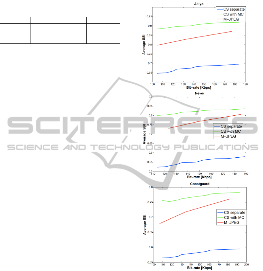
Table 2: SSI values between the original and the recon-
structed frames shown in Fig. 5.
M-JPEG CS w/o MC CS with MC
Akiyo 0.829 0.584 0.871
News 0.733 0.464 0.768
Coastguard 0.678 0.516 0.711
with the frame reconstructed using M-JPEG, as well
as with the proposed approach before and after apply-
ing the iterative refinement step. First, by comparing
the third and the fourth columns, presenting the recon-
structed frames by applying separate decoding and
by employing motion estimation and compensation at
the decoder, we can see the significant improvement
we are able to achieve via the iterative motion com-
pensation process. Moreover, the M-JPEG method is
sensitive to blocking artifacts as the number of quanti-
zation levels decreases, as it can be seen in the images
of the second column. The corresponding SSI values
between the original frames and the M-JPEG recon-
struction, along with the proposed approach without
and with the use of motion compensation are shown
in Table 2.
5 CONCLUSIONS
In the present work we introduced a compressive
video sensing method for a lightweight remote imag-
ing system. The limited memory, power, and band-
width resources of these systems necessitate the de-
sign of a very simple encoder, while putting the main
computational burden at the decoder. Motivated by
the simplicity of M-JPEG, the proposed CVS encoder
is able to achieve low bit-rates with a reduced com-
putational complexity, by combining a DCT-based
transform coding applied on the reference I-frames
with a CS-based compression applied on the (pos-
sibly downsampled) non-reference P-frames. At the
decoder, the inverse processes are followed to recon-
struct the I and P frames. However, the main draw-
back is the decreased reconstruction performance of
the P-frames when we work at very low sampling
rates. This problem is alleviated by applying an iter-
ative motion compensation at the decoder, acting as a
refinement step. Finally, when the acquired P-frames
are downsampled at the encoder, a dictionary-based
super-resolution method is employed at the decoder
to restore the reconstructed frames in their original di-
mension. As a general conclusion, the proposed CVS
system yielded a superior reconstruction quality com-
pared with M-JPEG, especially at low bit-rates.
Further improvements can be achieved by imple-
Figure 4: Comparison of reconstruction performance as a
function of the bit-rate between CVS and M-JPEG.
menting a more efficient CS reconstruction method,
resulting in an increased quality of the initially recon-
structed P-frames at very low sampling rates. More-
over, with the current implementation, the dictionary-
based super-resolution method cannot be applied ef-
ficiently in a real-time scenario, because of the delay
in updating the dictionary with previously decoded I-
frames. Thus, the design of new techniques for fast
dictionary update is necessary so as to enable the use
of the proposed method in a real-world application w-
DESIGN OF A COMPRESSIVE REMOTE IMAGING SYSTEM COMPENSATING A HIGHLY LIGHTWEIGHT
ENCODING WITH A REFINED DECODING SCHEME
53
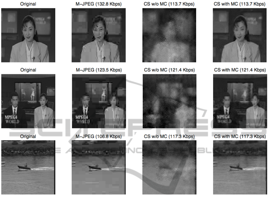
Figure 5: Visual inspection of the reconstruction performance for M-JPEG and the proposed CVS scheme.
ith time limitations at the decoder. When working at
very low sampling rates, we do not expect to achieve
the superior performance of an MPEGx-like profile,
which is based on the increased sparsity of the resid-
ual frames exploited at the encoder. However, as
the experimental results revealed, the reconstruction
quality of the proposed lightweight remote imaging
system is high enough so as to be effective in perform-
ing tasks such as detection and classification, which
are also of importance in several surveillance applica-
tions, and require a more thorough study.
ACKNOWLEDGEMENTS
This work is supported by CS-ORION Marie
Curie Industry-Academia Partnerships and Pathways
(IAPP) project funded by the European Commission
in FP7 (PIAP-GA-2009-251605).
REFERENCES
Blumensath, T. and Davies, M. (2009). Iterative hard
thresholding for compressed sensing. Applied and
Computational Harmonic Analysis, 27(3):265–274.
Cand
´
es, E., Romberg, J., and Tao, T. (2006). Robust
uncertainty principles: exact signal reconstruction
from highly incomplete frequency information. IEEE
Trans. on Information Theory, 52:489–509.
Do, T., Chen, Y., Nguyen, D., Nguyen, N., Gan, L., and
Tran, T. (2009). Distributed compressed video sens-
ing. In 43rd Annual Conf. Inf. Sci. and Sys. (CISS’09),
Baltimore, MD.
Do, T., Tran, T., and Gan, L. (2008). Fast compressive sam-
pling with structurally random matrices. In IEEE Int.
Conf. on Acoust., Speech and Sig. Proc. (ICASSP’08),
Las Vegas, NV.
Donoho, D. and Johnstone, I. (1994). Ideal spatial adapta-
tion by wavelet shrinkage. Biometrika, 81:425–455.
Freeman, T., Jones, T., and Pasztor, E. (2002). Example-
based super-resolution. IEEE Computer Graphics and
Applications, 22(2):56–65.
Jung, H. and Ye, J.-C. (2010). Motion estimated and com-
pensated compressed sensing dynamic magnetic reso-
VISAPP 2012 - International Conference on Computer Vision Theory and Applications
54

nance imaging: What we can learn from video com-
pression techniques. Intl. J. of Imaging Systems and
Technology, 20(2):81–98.
Kang, L.-W. and Lu, C.-S. (2009). Distributed compressive
video sensing. In IEEE Int. Conf. on Acoust., Speech
and Sig. Proc. (ICASSP’09), Taipei.
Prades-Nebot, J., Ma, Y., and Huang, T. (2009). Distributed
video coding using compressive sampling. In Picture
Coding Symp. (PCS’09), Chicago, IL.
Skretting, K., Husøy, J. H., and Aase, S. O. (1999). Im-
proved Huffman coding using recursive splitting. In
Norwegian Signal Proc. Symp., Norway.
Stankovi
´
c, V., Stankovi
´
c, L., and Cheng, S. (2008). Com-
pressive video sampling. In European Sig. Proc. Conf.
(EUSIPCO’08), Lausanne.
Wang, P., Hu, X., Xuan, B., Mu, J., and Peng, S. (2011). Su-
per resolution reconstruction via multiple frames joint
learning. In Intl. Conf. Multimedia and Signal Proc.
(CMSP’11), Guilin, Guangxi.
Yang, J., Wright, J., Huang, T., and Ma, Y. (2008). Im-
age super-resolution as sparse representation of raw
image patches. In Computer Vision and Pattern Rec.
(CVPR’08), Anchorage, AK.
Zhang, H., Zhang, Y., and Huang, T. (2011). Efficient
sparse representation based image super resolution via
dual dictionary learning. In Intl. Conf. Multimedia and
Expo (ICME’11), Barcelona.
DESIGN OF A COMPRESSIVE REMOTE IMAGING SYSTEM COMPENSATING A HIGHLY LIGHTWEIGHT
ENCODING WITH A REFINED DECODING SCHEME
55
