
Unified Software-knowledge Behavioral Model
Iaakov Exman
Software Engineering Department, Jerusalem College of Engineering
POB 3566, 91035, Jerusalem, Israel
Abstract. UML is a standard language for modeling software, consisting of
separate diagrams for structure, behavior and reasoning add-ons. But, even
though semantics is of increasing importance for software behavior, it is not
fully integrated within UML. We propose the integration of UML statecharts
with novel behavioral ontologies’ knowledge into a Unified Software-
Knowledge model. By construction, behavioral ontologies generate graphs
isomorphic to UML statecharts, facilitating their integration. This approach is
applied to run time measurements, needed to check the actual software beha-
vior correctness. Measurements discrepancies may trigger knowledge discovery
mechanisms to update the behavioral ontologies. The approach is illustrated
with statechart examples from the domain of GOF software design patterns.
1 Introduction
UML – the Unified Modeling Language (see e.g. [11] and the OMG standard [14]) –
is a de facto standard modeling language used for software development. It consists
of separate structure and behavior diagrams with logic OCL add-ons which have been
used for reasoning about class and state diagrams.
Semantics has been increasingly important for understanding and testing software
behavior. Nevertheless it is not directly represented in UML diagrams – see e.g. the
discussion by Selic [12] on the Semantics of UML.
An example of a problem of relevance to semantic application is checking by run-
time measurement the actual behavior correctness of a software package vis-à-vis the
declared behavior. For instance, if an observer design pattern most of the time actual-
ly behaves as an observer.
This work proposes, as an improvement of the solution to the run-time measure-
ment problem, the direct integration of semantics into UML statecharts, resulting in a
Unified Software-Knowledge behavioral model.
This approach is illustrated by statecharts and a novel type of behavioral ontolo-
gies from the domain of GOF
1
software design patterns [6].
In the remaining of the paper we review UML statecharts and describe the run-
time measurement problem in the context of design patterns (section 2), introduce the
1
GOF – Gang Of Four – is the well-known nickname of the authors of the book that introduced design
patterns in software engineering, viz. Gamma, Helm, Johnson and Vlissides (ref. [6]).
Exman I..
Unified Software-knowledge Behavioral Model.
DOI: 10.5220/0003705000750083
In Proceedings of the 2nd International Workshop on Software Knowledge (SKY-2011), pages 75-83
ISBN: 978-989-8425-82-9
Copyright
c
2011 SCITEPRESS (Science and Technology Publications, Lda.)

novel behavioral ontologies (section 3), propose concrete integration of ontologies’
knowledge within statecharts (section 4), and conclude with a discussion (section 5).
2 UML for Pure Software: Design Pattern Statecharts
UML is a standard modeling language for description of software during all its devel-
opment phases. Here we first review UML statecharts, then use them to explain the
run-time measurement problem.
2.1 Behavior: Statecharts
A statechart [7] is essentially made of states graphically represented by rounded rec-
tangular nodes, linked by edges standing for transitions. A transition may be labeled
by the following items
a) Event – a potential trigger of a transition; the same event may appear in various
transitions within the same statechart;
b) Guard – a Boolean expression, standing for a condition necessary for the transi-
tion to occur;
c) Action – an outcome generated, in case the event occurs; it may be the computa-
tion of a value, or invoking of another event.
Statecharts are not the only behavioral diagrams in UML. There are also sequence
diagrams – with an explicit time axis, useful to describe specific scenarios – and the
almost equivalent collaboration diagrams.
Statecharts were chosen in this work – in preference to other behavioral diagrams
– because they encompass all possible behaviors for a given system, instead of just
specific scenarios. For instance, a single statechart can cover all possible calls of a
mobile phone. One would need one different sequence diagram to describe each sce-
nario, such as a successful call, a busy line, a voice-mail message left, etc.
A statechart is essentially a type of labeled graph. This is an important feature for
integration of knowledge with software statecharts, as will be described in section 4.
2.2 Design Pattern Statecharts
While statecharts are in widespread use for system development, since they were
published in the late eighties by Harel [7], they were not systematically applied to
describe GOF design patterns. In particular, the GOF book [6] describes design pat-
terns by UML class and sequence diagrams, without statecharts.
The reasons for the conspicuous absence of statecharts from design pattern de-
scriptions are an interesting question per se. Instead of trying to explain it, we just
propose statecharts for sample patterns.
A sample statechart for the Singleton design pattern [6] is seen in Figure 1. This
and subsequent examples in this work are taken from the domain of GOF design
patterns.
76
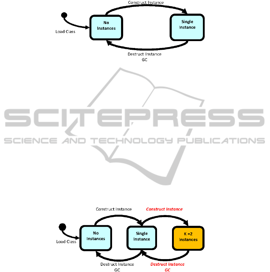
Fig. 1. UML Statechart of the Singleton design pattern – It displays two states and transitions
between states. The left arrow, labeled “Load Class”, stands for a default (initial) transition.
GC means Garbage Collection, a way to destruct the single instance.
The Singleton design pattern, depicted in the statechart of Fig. 1, perfectly charac-
terizes the declared behavior of a singleton: either zero or exactly one instance.
2.3 Run-time Pattern Measurements
In order to allow actual run-time measurements – observing whether an implemented
pattern complies with the perfect declared behavior – we need a more general model
that takes into account that things can go wrong.
A more general model – including possible misbehaviors – is seen in the example
statechart of Figure 2. This statechart has an added state with K=2 instances, contra-
dicting the definition of a singleton.
Such statechart with misbehaviors is not unique. For instance, it could have addi-
tional transitions from the illegal state (K=2 instances) to other states, enabling crea-
tion and destruction of additional instances. The number of additional misbehaviors
has an unbounded value K.
Fig. 2. UML Statechart of the Singleton design pattern with misbehaviors – It has an additional
illegal state (K=2 instances) and forbidden transitions to/from this state (Construct Instance and
Destruct Instance in bold italics, red colored).
The “run-time pattern measurement” problem is defined as follows: given a soft-
ware program which implements a design pattern, and a statechart of the design pat-
tern containing possible misbehaviors, perform measurements of the program beha-
vior to check that no forbidden transitions are performed.
77

In this context – i.e. statecharts containing misbehaviors – semantics enters the
stage to tell us, e.g. whether a transition is forbidden or a state is illegal.
3 Ontologies
Ontologies are graphs
2
[15] used to express semantics involving concepts. Specia-
lized tools make inferences based upon the knowledge expressed in ontologies.
We describe here a novel type of ontologies, coined behavioral ontologies.
3.1 Behavioral Ontologies
An ontology is a directed labeled graph whose vertices are concepts and edges are
relations between concepts. Typical relations between concepts in a structural ontolo-
gy are: a) sub-type; b) composition; d) domain dependent relations.
A software behavioral ontology is a novel type of ontology explicitly referring to
software behavior concepts (i.e. states and transitions), with kinds of relations refer-
ring to these and relevant concepts.
The single most important new concept in a behavioral ontology – besides states
and transitions – is “eventuality”. Eventuality in natural language means a “possible
occurrence or outcome”. We shall refer to concepts of either “transition eventuality”
or “state eventuality”, meaning the a priori knowledge one has about the eventual
occurrence of a transition or the outcome of being in a state.
Eventuality is composed of three concepts:
a) Authorization – is a Boolean concept; the model developer – the authority – de-
cides that a transition is either "forbidden" or "allowed"; a state is either "legal" or
"illegal";
b) Probability – this is the probability of occurrence of a transition or that an out-
come is a given state; a probability can be expressed numerically or qualitatively, say
it is either low or high probability;
c) Constraints – specific domain dependent constraints; say in the real time domain,
a transition may not occur before a certain timeout.
It is important to point out that authorization and probability are not redundant con-
cepts. A forbidden transition does not necessarily imply zero probability. A forbidden
transition may have a finite non-zero probability of occurrence, even if it is desirable
to have a low probability in this case (see e.g. the discussion of the Observer design
pattern below).
Figure 3 displays a software behavioral ontology as a graph.
The authorization notion was illustrated by the Singleton example: in Fig. 2 there
were both legal and illegal states. The singleton pattern does not involve probabilities,
since all transitions not within the perfect declared behaviors are forbidden, with zero
probabilities.
2
Graphs – as noted by Weisstein [15] – have two different meanings: 1- a graphical plot; 2-an abstract
mathematical entity. We refer here to the second meaning.
78
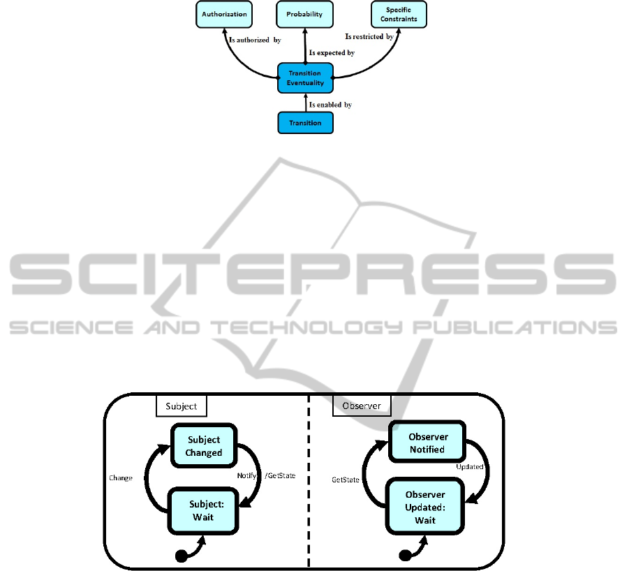
Fig. 3. Software Behavioral Ontology as a graph – it displays the concepts for transitions be-
tween states. The central concept of "Transition Eventuality" is composed of three concepts:
authorization, probability and specific constraints. The behavioral ontology for states is iden-
tical, except that one should substitute "transition" by "state" and "transition eventuality" by
"state eventuality".
In order to explain the probability notion let us look at another example, the Ob-
server pattern [6]. This pattern has two roles: a subject that may change and observers
that are notified of the subject change, ask for the subject new state, and are updated.
In Figure 4 one sees a partial statechart representing the notify-update cycle of the
subject and a respective observer. Observers can be attached or detached to the sub-
ject as needed. The latter actions are not represented in this statechart.
The perfect Observer complies with the notify-update cycle, i.e. messages are al-
ways in this order: first the subject notifies the observers, then each observer requests
the subject state by a Get-State message, finally each observer is updated.
Fig. 4. Observer pattern partial statechart – the states separated by the dashed line work in
parallel: the states of the subject and of the observer are independent. For the perfect Observer
pattern the notify-update cycle is always obeyed.
Now we are ready to understand why the notion of probability is relevant to the
Observer pattern. If the subject and observers are not in the same machine, they
communicate by TCP/IP messages. Since IP messages may travel through different
routes and sometimes are lost, the Observer pattern cycle is not always perfect. Thus
there is a low but finite probability of changing message orders. It should be stressed
that, even with low probability mistakenly ordered messages, we could still accept
such a program as a correct implementation of the Observer pattern (cf. ref. [13] on
measurement of Observer patterns).
79
4 Integration of Software and Knowledge in a Unified Model
By construction, behavioral ontologies display a one to one correspondence between
a transition or a state and their respective "eventuality" (in Fig. 3).
Thus for each statechart entity – either state or transition – there is a behavioral
ontology eventuality: one obtains a strict isomorphism between the software only
UML statechart and the graph obtained by labeling states and respective transitions
by their corresponding eventualities. We claim that there is no reason to keep them
separated: their integration is desirable by reasoning and efficiency considerations.
4.1 Behavioral: Integrated Statecharts
Practical integration of statecharts with behavioral ontology labels is quite
straightforward. Semantic information is added as a new kind of attribute fields –
SKB-fields standing for Software-Knowledge-Behavior fields – of states and transi-
tions.
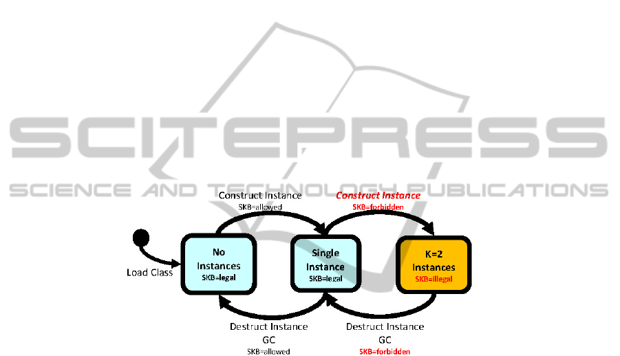
A schematic example of integrated statechart is seen in Figure 5 for the Singleton
with misbehaviors.
Fig. 5. Integrated Statechart model of Singleton pattern with misbehaviors – This statechart
schematically displays legal/illegal states, allowed/forbidden transitions within integrated
semantic SKB-fields.
4.2 Usage of Integrated Behavioral Models
The idea of usage of integrated behavioral models is as follows. The Unified Model
contains states and transitions for the declared behaviors of the chosen pattern. It also
contains additional states and transitions representing expected misbehaviors. The
SKB fields label the states and transitions with the a priori knowledge one has about
the pattern, i.e. the eventualities for states and transitions.
Next one performs measurements of the actual behavior of a software system that
implements the pattern. A typical measurement is the frequency of notify messages
within a subject transition preceding GetState messages from its observers, in the
Observer pattern.
80

Then one compares the measured frequencies with the a priori probabilities in the
Unified Model. One might conclude that: a- the model is accurate and the implemen-
tation correctly reflects the model; b- the implementation is faulty; c- the model is
inaccurate and its knowledge should be updated.
In practice, to use the Unified models that were proposed one typically needs a
knowledge base, independent of the case under test to be measured. Since the know-
ledge base is a relatively small addition to a standard statechart, our claim is that
Unified models should speed-up the solution of a run-time measurement problem.
5 Discussion
The main argument for software and knowledge integration is that one actually starts
software development from fundamental concepts about the system, in other words
one starts from structural and behavior knowledge. One should not lose sight of
knowledge, when the software is gradually developed.
An important issue, besides the feasibility of integration, is applicability. We
mean the kinds of inferences that can be done with the integrated models.
The run-time measurement problem refers both to the overall correctness of the
design pattern behavior, and to the efficiency of the pattern behavior. For instance,
suppose one expects a low probability of occurrence of certain transitions due to
message losses, and the resulting measurements indicate a higher than expected prob-
ability. This points out to a system needing redesign.
5.1 Related Work
There are a few sets of ontologies related to GOF design patterns, most of them struc-
tural. For instance, reference [4] contains examples in OWL of a sub-set of GOF
patterns. Another set – the design pattern intent ontology [9] – also deals systemati-
cally with GOF patterns. Its purpose is more of a classificatory nature, aiming to help
the user to find the most adequate design pattern that fits to one’s development.
There exist also proposals for statechart specific patterns – differing from the
GOF ones. Such a proposal is found in ref. [16].
The closest kinds of work to ours are the relatively rare application of ontology-
based approaches to software behavior. Reference [8] describes such an application to
malware behavioral analysis. Reference [1] deals with software process behaviors
within organizations.
The approach proposed here has several similarities to Model Checking tech-
niques (see e.g. [3]) using Kripke structures instead of integrated statecharts, to make
inferences about systems. For example, it describes systems by graphs in which states
are labeled with atomic propositions which are true in these states. System models –
e.g. of a microwave oven – contain both allowed and ‘undesirable’ transitions. On the
other hand, Model Checking does not require a system implementation and does not
perform measurements.
OCL – the Object Constraint Language – has been used for reasoning about class
81

diagrams (see e.g. Clavel et al. [2] and Queralt and Tenient [10]) and about state
diagrams (see e.g. Flake and Muller [5]).
5.2 Future Work
The examples in this position paper are only of an introductory nature.
One should extensively investigate a variety of software systems of practical in-
terest. This may lead to a different characterization for behavioral ontologies and the
SKB-fields. There could be values of a different nature or even small data structures
within states.
Concerning the inference techniques, one could add different forms to time repre-
sentation, say the operators of temporal logic [3] and explicit real-time constraints.
5.3 Main Contribution
The main contribution of this work is the proposal of integrated software knowledge
behavioral models. In particular, as a knowledge discovery technique, it is important
to model misbehaviors, as well as allowed/legal behaviors. Unified models represent
an alternative to disconnected diagrams in an already cluttered UML zoo of diagrams.
References
1. Barcellos, M. P., Falbo, R. A. and Rocha, A. R.: A Well-founded Software Process Beha-
vior Ontology to Support Business Goals Monitoring in High Maturity Software Organiza-
tions, in 14
th
IEEE Int. Enterprise Distributed Object Computing Conf. Workshops, pp.
253-262, (2010).
2. Clavel, M., Egea, M. and de Dios, M. A. G.: Checking Unsatisfiability for OCL Con-
straints, Elec. Comm. EAAST, Vol. 24, 1-13 (2009).
3. Clarke Jr., E. M., Grumberg, O. and Peled, D. A.: Model Checking, MIT Press, Cambridge,
MA, (1999).
4. Design Pattern Ontologies, http://www.cs.uwm.edu/~alnusair/ontologies/patterns.html
5. Flake, S. and Mueller, W.: Formal semantics of static and temporal state-oriented OCL
constraints, Softw Syst Model (2003).
6. Gamma, E., Helm, R., Johnson, R. and Vlissides, J.: Design Patterns – Elements of Reusa-
ble Object-Oriented Software, Addison-Wesley, Boston, MA, (1995).
7. Harel, D.: On Visual Formalisms, Comm. of the ACM, Vol. 31, No 5, (1988).
8. Huang, H. D., Chuang, T. Y., Tsai, Y. L. and Lee, C. S.: Ontology-based Intelligent Sys-
tem for Malware Behavioral Analysis, in Proc. WCCI2010, (2010).
9. Kampffmeyer, H.: The Design Pattern Intent Ontology – Finding the Pattern you need,
VDM Verlag Dr. Muller, Saarbrucken, Germany, (2007).
10. Queralt, A. and Tenient, E.: Reasoning on UML Class Diagrams with OCL Constraints, in
D. W. Embley, A. Olive, and S. Ram, editors, Conceptual Modeling, ER, LNCS Volume
4215, 497-512 (2006).
11. Rumbaugh, J., Jacobson, I. and Booch, G.: The Unified Modeling Language Reference
Manual, Addison-Wesley, Boston, MA, 2nd ed. (2004).
12. Selic, B. V.: On the Semantic Foundations of Standard UML 2.0, in M. Bernardo and F.
82

Corradini (Eds.): SFM-RT 2004, LNCS 3185, pp. 181–199 (2004).
13. Teplitsky, M. and Exman, I.: Measuring Behavioral Software Design Patterns, in Proc.
IEEEI-2006, 24
th
IEEE Convention of Electrical & Electronics Engineers in Israel, pp. 384-
388, Eilat, Israel (2006).
14. UML – Unifying Modelling Language – Version 2.4 Beta 2 – March 2011, OMG – Object
Management Group Specification, Web site: http://www.omg.org/spec/UML/2.4/.
15. Weisstein, E. W.: Graph, From MathWorld - A Wolfram Web Resource. Web Site:
http://mathworld.wolfram.com/Graph.html
16. Yacoub, S. M. and Ammar, H. H.: A Pattern Language of Statecharts, in Proc. PLoP-98
Conference (1998).
83
