
A MODEL-DRIVEN SYSTEMS DEVELOPMENT METHOD
FOR MANAGEMENT INFORMATION SYSTEMS
Keinosuke Matsumoto, Tomoki Mizuno and Naoki Mori
Graduate School of Engineering, Osaka Prefecture University, Sakai, Osaka, Japan
Keywords: Model-driven development, Model theory approach, UML, Graphic diagrams, Transaction processing
system.
Abstract: Traditionally, a Management Information System (MIS) has been developed without using formal methods.
By the informal methods, the MIS is developed on its lifecycle without having any models. It causes many
problems such as lack of the reliability of system design specifications. In order to overcome these
problems, a model theory approach was proposed. The approach is based on an idea that a system can be
modeled by automata and set theory. However, it is very difficult to generate automata of the system to be
developed right from the start. On the other hand, there is a model-driven development method that can
flexibly correspond to changes of business logic or implementing technologies. In the model-driven
development, a system is modeled using a modeling language such as UML. This paper proposes a new
development method for management information systems applying the model-driven development method
to a component of the model theory approach. The experiment has shown that a reduced amount of efforts is
more than 30% of all the efforts.
1 INTRODUCTION
Traditionally, a Management Information System
(MIS) has been developed without using formal
methods. By the informal methods, the MIS is
developed on its lifecycle without having any
models. It causes many problems such as lack of the
reliability of system design specifications. In order
to overcome the problem, some formal approaches
to the MIS development have been developed.
Vienna development method (Fitzgerald & Larse,
1998) is one of the most popular methods. It designs
a system based on a system model, and the model is
described in the set theory (Cantone et al., 2001) and
the logics. In addition, Takahara et al. proposed a
unique systems development method, a model
theory approach (Takahara et al., 2005a; Takahara et
al., 2005b; Takahara & Liu, 2006). This approach is
based on an idea that a system can be modeled by
automata and set theory. An automaton consists of
two or more states and a function that defines what
processing is performed to an input in each state.
However, it is very difficult to generate automata of
the system to be developed right from the start. On
the other hand, there is a model-driven development
method (Kleppe et al., 2003; Mellor et al., 2003;
Selic, 2003; Völter et al., 2006) that can flexibly
correspond to changes of business logics or
implementing technologies. In the model-driven
development, a system is modeled using a modeling
language such as UML (Unified Modeling
Language) (UML, n.d.). Generating source codes
automatically reduces developing cost and makes
consistency of design and implementing.
It is possible to combine the model-driven
development and the model theory approach to bring
advantages of the both methods. This paper proposes
a new development method for management
information systems applying the model-driven
development method to a component of information
system of the model theory approach. This research
aims at cutting down the amount of efforts by
applying the proposed method.
2 MODEL THEORY APPROACH
This chapter explains the model theory approach
(Takahara & Liu, 2006). According to Takahara et
al., automata can describe arbitrary information
systems. The model theory approach is proposed as
a development method of management information
10
Matsumoto K., Mizuno T. and Mori N..
A MODEL-DRIVEN SYSTEMS DEVELOPMENT METHOD FOR MANAGEMENT INFORMATION SYSTEMS .
DOI: 10.5220/0003061300100016
In Proceedings of the International Conference on Knowledge Engineering and Ontology Development (KEOD-2010), pages 10-16
ISBN: 978-989-8425-29-4
Copyright
c
2010 SCITEPRESS (Science and Technology Publications, Lda.)
systems using this theory.
2.1 MIS
A management information system consists of two
components: a Problem Solving System (Solver) and
a Transaction Processing System (TPS). The former
is a system which offers some supports or answers
when, how, and how much to dispatch goods. The
latter is a system which deals with daily regular
business activities in respect of recording sales or
updating goods in stock. They are possible to
independently operate on a constructing system, and
also can be combined to realize more complicated
systems.
This paper focuses on the TPS of management
information systems, and introduces the model
theory approach to its design and implementation.
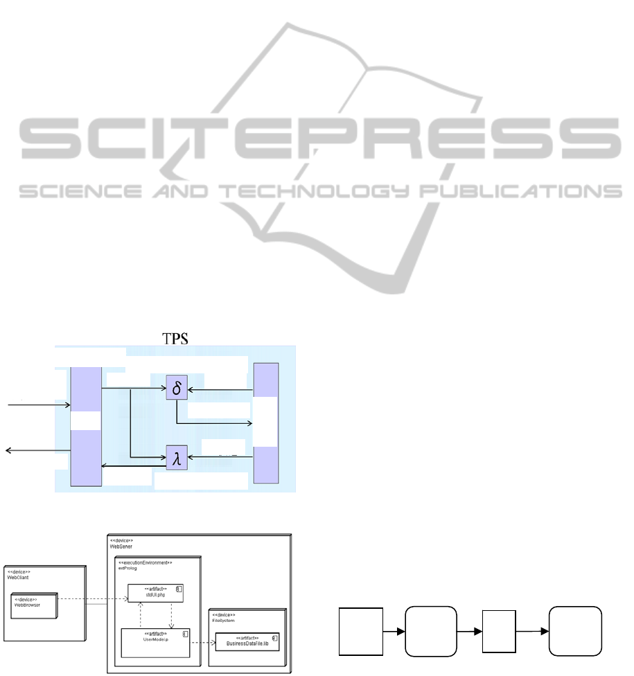
Fig. 1 shows an outline of structure of the TPS. The
TPS is modeled regarding a file system or database
as a state, user’s operation as input, and response to
a user from the system as an output. Therefore, it is
necessary to define states, inputs, outputs, state
transition functions, output functions and so on that
consist of elements of automata to implement the
TPS.
The TPS is implemented as a Web application as
shown in a deployment diagram of the TPS shown in
Fig. 2. UserModel.p in Fig. 2 is a compiled and
executable file of implemented codes of the
TPS.
Figure 1: Structure of the TPS.
Figure 2: TSP deployment diagram.
Moreover, stdUI.php is a PHP (PHP, n.d.) program
which is a user interface of the TPS. It changes
automatically contents in accordance with
UserModel.p. Therefore, it is possible for a
developer of the TPS not to edit stdUI.php, but also
to edit it to change the user interface arbitrarily.
BusinessDataFile.lib is a business data file. The user
of the TPS can use the system by accessing Web
server, using a browser as a Web client.
A TPS Solver consists of processes that model a
problem as automata and solving program goal-
seeker. The Solver considers problem specifications
as inputs, and solutions as outputs.
2.2 Computer Acceptable Set Theory
The model theory approach uses a description of set
theory called Cast (Computer Acceptable Set
Theory) (Takahara & Liu, 2006) as a language to
design and implement the TPS and Solver. Cast
enables us to express set theory, proposition logic,
and predicate calculus, and it can deal with
automata. Takahara et al. have improved
development environment and execution
environment of Cast. All Cast codes are
implemented by hand from the automata in the
model theory approach.
3 MODEL-DRIVEN
DEVELOPMENT METHOD
This section describes a model-driven development
method. A transformation process of the method is
shown in Fig. 3. The goal of the method is to
develop a software system using abstract models
such as UML models, and then refine and transform
these models into source codes. The real power of
the method comes from automating these processes.
Such transformations accelerate the processes, and
result in better code quality. JET (Java Emitter
Templates) (Marz & Aniszczyk, 2006) is used for
transforming models into source codes. JET is one
of EMF (Eclipse Modeling Framework) (EMF, n.d.)
project results and it is a code generation technique
for improvement in productivity. A code-generator
is an
Figure 3: Model-driven development method.
t
t
r
r
a
a
n
n
s
s
f
f
o
o
r
r
m
m
M
M
o
o
d
d
e
e
l
l
s
s
M
M
o
o
d
d
e
e
l
l
E
E
d
d
i
i
t
t
o
o
r
r
JET
S
S
o
o
u
u
r
r
c
c
e
e
C
C
o
o
d
d
e
e
s
s
o
o
u
u
t
t
p
p
u
u
t
t
Interface
Input
Output
State
State
Next State
Output function
State transition function
Business
data
Response
I/F
Memory
WebBrowser
stdUI.
p
h
p
UserModel.
BusinessDataFile.li
A MODEL-DRIVEN SYSTEMS DEVELOPMENT METHOD FOR MANAGEMENT INFORMATION SYSTEMS
11

important component of model-driven development.
In JET, codes are outputted using templates. Models
can be applicable to various systems by changing
templates. JET is also useful to raise the reusability
of models.
4 PROPOSED METHOD
This chapter describes a proposed method. The
method applies the model-driven development
method to develop the TPS in the model theory
approach, and cuts down the amount of development
efforts. A concrete process is as follows:
(1) Design of Platform Independent Models from
Requirement Specifications
(2) Design of Platform Specific Models
(3) Automatic Generation of Source Codes
written by Cast from the platform specific
models
4.1 Details of the Proposed Method
To generate Cast codes of the model theory
approach using the model-driven method needs
requirement specifications of a system and a model
of the TPS. The former describes only requirement
specifications, and it does not include information
on the TPS. In other words, they are independent
models on implementing technologies. Therefore, it
is necessary to use a flexible and general modeling
language. The proposed method uses UML. On the
other hand, the latter is a model to be designed and
developed by the TPS. The proposed method defines
an original model and uses it for the latter. This
model will be called a TPS model. For creating the
model from requirement specifications, the proposed
method uses UML diagrams to design the TPS
model, and an automatic code generation method to
transform the TPS model into Cast codes.
4.2 Modeling Requirement
Specifications using UML
UML is defined as a notation of models in order to
advance analysis, design, and implementing of a
system. UML defines only the notation of models,
but it does not include systems development
methodology. The latest version is UML2.1
(UML2.1, n.d.) and it consists of 13 different kinds
of diagrams. The reason why the proposed method
uses UML is that it is one of the most widely used
modeling languages at present. It is important to use
a modeling language being used widely because
users and developers can understand their intentions
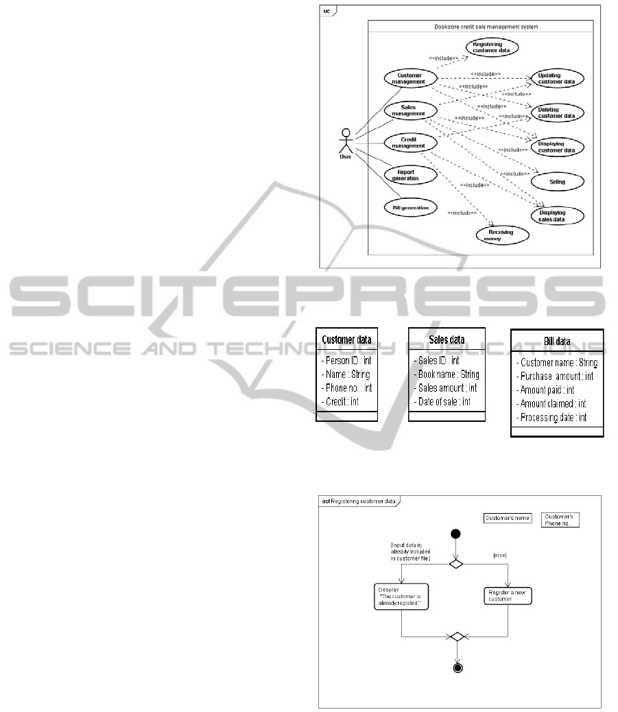
Figure 4: Inclusion relationship between use cases.
to each other. The proposed method uses the
following diagrams to model requirement
specifications:
(1) Use Case Diagram. A use case diagram
expresses functions to be implemented. The
functions correspond to interface elements I/F of
Fig. 1, and they are defined by a use case diagram.
To describe the TPS, you must define functions
(main use case) whose granularity are comparatively
large, and indivisible functions (sub use case) that
are contained in a main use case. This relation of the
use cases can be expressed by using inclusion
relation of UML2.1. The inclusion relation between
a main use case and a sub use case may be in the
relation of many-to-many. An inclusion relation is
described using include stereotype. Fig.4 shows this
situation.
(2) Class Diagram. A class diagram defines
attributes of a data file for business. The data file is
stored in a file system or a database, and
corresponds to a memory (DB) in Fig. 1. The usage
of a class diagram in the proposed method is closer
to an entity in Entity-Relationship diagram than a
concept of the class in object-oriented development.
An attribute is defined so that it may be normalized
in third normal form in a relational database.
(3) Activity Diagram. An activity diagram expresses
a process to realize sub use cases and user defined
functions. An activity diagram is created for every
sub use case defined by the use case diagram. This
corresponds to state transition function δ and output
function λ shown in Fig. 1. A user does not need to
consider that a movement of the system is an
automaton, but just to describe them like a
flowchart.
A system developer creates these UML diagrams
at first, and creates specific models for the TPS. Cast
code generation from the model is performed using
this TPS model and the activity diagrams.
4.3 Designing TPS Model for Code
Generation
A TPS model is an original defined model of the
proposed method. We have designed a meta-model
which defines a TPS model itself. The structure of
Main
use case
Sub
use case
KEOD 2010 - International Conference on Knowledge Engineering and Ontology Development
12
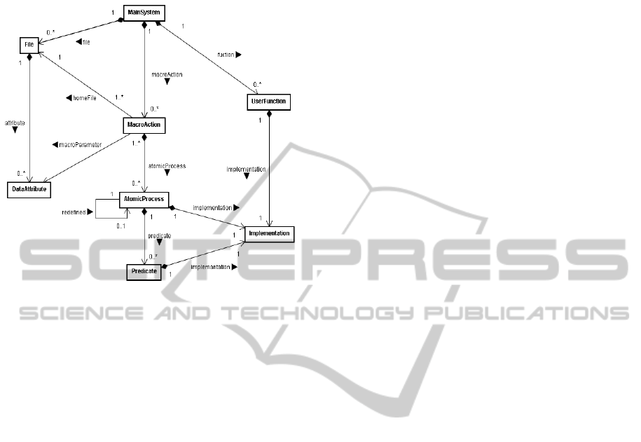
the meta-model is shown in Fig. 5. This meta-model
contains structure of the TPS, and it is used as a
Figure 5: Meta-model of TPS model.
direct input for code generation. A user designs this
TPS model using the above-mentioned UML
diagrams. UML diagrams do not depend on the
model theory approach, but only depending on
specifications of a system. TPS model is designed
for implementing the system by the model theory
approach.
4.4 Automatic Cast Code Generation
In the model-driven development, models, such as
UML diagrams, are stored as a file in XML
(eXtensible Markup Language) (XML, n.d.) form. It
enables to exchange data of the models between
modeling tools for the model-driven development.
Therefore, this XML file is analyzed in order to
generate Cast codes from the models. Rules that map
model elements in the XML file onto Cast codes are
created. The models are transformed into Cast codes
using these rules and JET technology.
4.5 TPS Development Tool for
Realizing the Proposed Method
A TPS development tool is implemented as a plug-in
of an integrated development environment Eclipse
(Eclipse, n.d.) for realizing the proposed method.
The functions of the TPS development tool are listed
as follows:
(1) Construction of a Project. This function builds a
specific project for TPS development on a work
space of Eclipse. A user can use this function calling
a wizard from Eclipse. A specific icon is displayed
so that user may be easy to distinguish the project
from other projects on the work space. Whenever
you build a project, the tool automatically generates
necessary folders and templates of UML diagrams.
(2) Transformation to TPS Model. This function
analyzes use case diagrams and class diagrams to
transform into TPS model. A user calls a wizard and
should just input required information.
(3) TPS Model Editor. This is a function for editing
TPS model. It can also output TPS model in XML
form. It is implemented using EMF. A user designs
TPS model using this editor.
(4) Code Generation from Models. This function
generates codes using JET. JET engine maps TPS
model onto skeleton codes according to contents of
JET templates, and generates concrete codes. Since
TPS model is stored in XML form by the TPS model
editor, it can be transformed into Cast codes of the
TPS using JET templates.
(5) Editing Support Function of Cast Codes. This
function supports for editing generated Cast codes.
5 EXPERIMENT AND RESULTS
An experiment has been carried out to show the
validity of the proposed method. The proposed
method has been applied to one of TPS examples
shown in (Takahara et al., 2005b) and implemented
using the development tool explained in Chapter 3.
This chapter shows results and discussions of the
application experiment.
5.1 Contents of an Experiment
A bookstore credit sale management system is taken
as one of examples of TPS applications. The aim of
the experiment is to investigate how many efforts for
developing TPS can be reduced by using the
proposed method. The TPS development tool is used
for the proposed method. On the other hand, hand
coding of all codes of TPS (we call it a conventional
method) is carried out as the comparison of quantity
of efforts. We introduce a method (Matsumoto et al.,
2010) how to quantify the amount of development
efforts: It supposes that equal amount of efforts to
add one node by the model editor and to describe
one line of source code. The number of nodes of
UML diagrams that are needed for applying the
proposed method and the rate of automatic
A MODEL-DRIVEN SYSTEMS DEVELOPMENT METHOD FOR MANAGEMENT INFORMATION SYSTEMS
13
generation of Cast source codes are computed. As a
result, the efforts of the proposed method and the
conventional method are compared.
5.2 Requirement Specifications
Specifications of the bookstore credit sale
management system are as follows:
(1) Customer Management. The system registers a
new customer, and update or delete data of an
existing customer. In the case of a new customer, the
system suggests to register the new customer.
(2) Sales Management. The system adds new sales
data and updates the customer’s accounts receivable.
(3) Credit Management. Customer’s credit data are
recorded and its accounts receivable are updated.
(4) Report Generation. The system generates a credit
sale balance report.
(5) Bill Generation. The system generates a bill for
every customer.
5.3 Model Design
A use case diagram and a class diagram are created
from the requirement specifications. The use case
diagram and the class diagram are shown in Figs 6
and 7 respectively. But, sub use cases of the report
generation function and the bill generation function
are omitted in Fig. 6.
TPS model is generated from the completed use
case diagram and the class diagram. An activity
diagram is created from TPS model. A part of
activity diagram corresponding to the customer
management use case is shown in Fig. 8. The
rectangle nodes described in Fig. 8 are input data;
we call them activity parameter nodes. After
creating a middle file from the activity diagram,
codes are generated using it.
Nodes inputted by hand are 69 in all UML
diagrams to model the bookstore credit sale
management system. There are more nodes actually
in UML diagrams than these. It is because a part of
nodes of UML diagrams are automatically generated
as a template at the time of creating a TPS project by
a wizard. The nodes generated automatically are two
use case nodes in a use case diagram, and one class
node in a class diagram. For each activity diagram,
one start node, one end node, one activity node, and
two activity parameter nodes are added
automatically.
Figure 6: Use case diagram of bookstore credit sale
management system.
Figure 7: Class diagram of bookstore credit sale
management system.
Figure 8: Activity diagram for registering customer data.
5.4 Code Generation Results of
Customer Data
Code generation results are shown in Table 1.
Where, logic LOC (Lines Of Code) is a number of
lines except for blank lines and comment lines. In
addition, “
Total Nodes” column shows the number of
KEOD 2010 - International Conference on Knowledge Engineering and Ontology Development
14
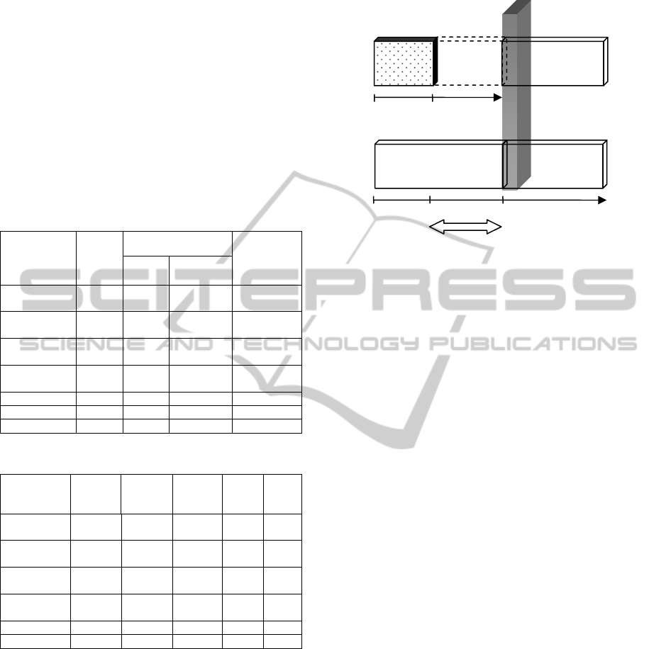
nodes inputted by hand at modeling. A numerical
value of “Total codes” column is a logic LOC of
codes shown in the book (Takahara & Liu, 2006). A
number in Table 2 is a value that the number of
nodes generated automatically is subtracted from the
number of nodes contained in each model.
Therefore, the value of use case column of the
customer management function in Table 2 is 3 (=5-
2).
Table 1 shows that automatic generation rate is
60.2 (=148×100/246) % of all the completed codes.
In addition, the codes generated automatically are
Table 1: Code generation results for bookstore credit sale
management system.
Function
Name
Total
Nodes
Logic LOC
Automatic
Generation
Rate
Total
Codes
Automatic
Customer
management
14 50 33 66.0%
Sales
management
9 25 18 72.0%
Credit
management
6 20 18 90.0%
Report
generation
14 60 29 48.3%
Bill generation 20 79 41 51.9%
Others 6 12 9 75.9%
Total sum 69 246 148 60.2%
Table 2: Number of inputted nodes for each function.
Function
name
Use
case
diagram
Class
diagram
Activity
diagram
TPS
model
Total
sum
Customer
management
3 0 11 0 14
Sales
management
3 0 6 0 9
Credit
management
2 0 4 0 6
Report
generation
4 0 10 0 14
Bill generatio
n
4 0 16 0 20
Others 0 2 0 4 6
the same as that indicated by the book of the model
theory approach. There is no necessity for correcting
the automatic generated codes in order to complete
the codes. In addition, Fig. 9 shows reduced amount
of efforts computed from Table 1. Since number of
inputted nodes in modeling is 69, the rate of
modeling efforts to 148 automatic generated lines of
codes is 46.6 (=69×100/148) % because amount of
efforts adding one node is supposed to be equal to
describing one line of source code. These results
proves that the proposed method can cut down
Figure 9: Efforts ratios of bookstore credit sale
management system.
32.1% of all amount of efforts compared to the
conventional method of hand coding of all the
source codes.
Besides reduction of efforts, the models which
are not dependent on implementing technologies are
acquired as an advantage of the model-driven
development.
6 CONCLUSIONS
This paper has proposed a new development method
for management information systems applying the
model-driven development method to a component
TPS of the model theory approach. We have
developed a TPS development tool for the proposed
method. To show the validity of the proposed
method, an experiment has been carried out using
the tool. The experiment of the proposed method has
shown good results, and the reduced amount of
developing efforts is more than 30% of all the
efforts.
As a future subject, improvement of JET
templates is necessary to increase the amount of
reduced efforts by the proposed method. We also
need to establish a modeling method from
requirement specifications to UML diagrams, and a
better quantification technique for efforts.
ACKNOWLEDGEMENTS
This work was partially supported by JSPS
KAKENHI 21560430.
100%
60.2%
0%
Codes
28.1%
32.1%
Codes
Proposed
metho
d
Conventional
metho
d
Developed parts
by hand
Codes
Nodes
Automatic
developed parts
46.6%
0%
100%
A MODEL-DRIVEN SYSTEMS DEVELOPMENT METHOD FOR MANAGEMENT INFORMATION SYSTEMS
15

REFERENCES
Cantone, D., Omodeo, E., Policriti, A., 2001. Set Theory
for Computing, Springer.
Eclipse, http://www.eclipse.org
EMF, http://www.eclipse.org/modeling/emf
Fitzgerald, J., Larse, P. G., 1998. Modeling Systems,
Cambridge University Press.
Kleppe, A., Warmer, J., Bast, W., 2003. MDA Explained,
the Model Driven Architecture: Practice and Promise,
Addison-Wesley.
Marz, N., Aniszczyk, C., 2006. Create more -- better --
code in Eclipse with JET, IBM Developer Works
Article.
Matsumoto, K., Maruo, T., Murakami, M., Mori, N., 2010.
A Graphical Development Method for Multiagent
Simulators: Cakaj, S. (Eds.), Modeling Simulation and
Optimization - Focus on Applications, pp. 147-157,
INTECH.
Mellor, S. J., Clark, A.N., Futagami, T., 2003. Model-
driven development - Guest editor’s introduction,
IEEE software, Vol.20, No.5, pp.14-18.
PHP, http://www.php.net
Selic, B., 2003. The pragmatics of model-driven
development, IEEE software, Vol.20, No.5, pp. 19 -
25.
Takahara, Y., el al., 2005. System Development
Methodology: Transaction Processing System in
MGST Approach, J. of the Japan Society for
Management Information, Vol.14, No.1, pp.1-18.
Takahara, Y., Liu, Y., Chen, X., Yano, Y., 2005. Model
Theory Approach to Transaction Processing System
Development, Int. J. of General Systems, Vol.3, No.5,
pp.537-557.
Takahara, Y., Liu, Y., 2006. Foundations and
Applications of MIS: a Model Theory Approach,
Springer-Verlag.
UML, http://www.uml.org
UML2.1 Superstructure Specification,
http://www.omg.org/
Völter, M., Stahl, T., Bettin, J., Haase, A., Helsen, S.,
2006. Model-Driven Software Development:
Technology, Engineering, Management, Wiley.
XML, http://www.w3.org/XML
KEOD 2010 - International Conference on Knowledge Engineering and Ontology Development
16
