3D OBJECT MEASUREMENT BY SHADOW MOIRÉ
Yun-Long Lay
1
,
Hui-Jen Yang
2
, Chern-Sheng Lin
3
and Wei-Yu Chen
1
1
Dept. of Electronic Engineering, National Chin-Yi University of Technology, Taichung, Taiwan
2
Dept. of Information Management, National Chin-Yi University of Technology, Taichung, Taiwan
3
Institute of Automatic Control Engineering, Feng Chia University, Taichung, Taiwan
Keywords: Shadow Moiré, Optical measurement system, Mouth shape measurement, Image processing.
Abstract: In order to get the 3 dimensional data of an object, this research applied a shadow Moiré method to build an
optical measurement system without touching the object to measure the contour for getting a 3D data. A
digital camera was used to capture the Moiré images through an image processing to get the texture of each
contour line. After calculated the texture of each contour line, the correspondence values are then filled.
Each correspondence value will make smooth contour interpolation and then three-dimensional image of the
object was plotted. This method for 3D measurement is simple and does not need an expensive
measurement device to get precisely image information for a 3D rebuilt implementation.
1 NON-TOUCHING
3-DIMENSIONAL
MEASUREMENT METHOD
Non-touching measurement method is to use a laser
or light interference measuring the objects. There
will be no touching wear or contact vibration to
cause bias. This method is very suitable to measure
the soft materials. In addition, its application domain
is wide, such as industrial model design process,
reverse engineering, medical engineering, surgery
simulation, 3D animation and so on. The followings
are some common non-touching three-dimensional
profile measurement methods (Fu, 1997).
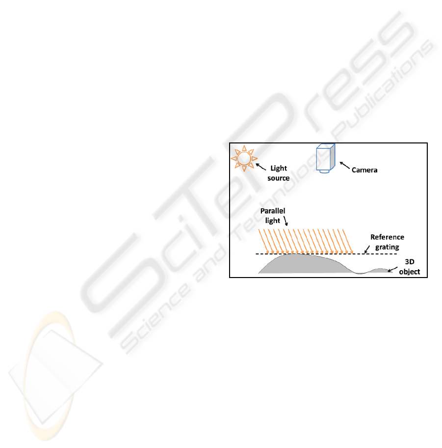
Shadow Moiré is the method applied in this
study, shown in Figure 1. The experimental devices
include a reference grating, light source and digital
camera. The light source projects on the grating with
a specific angle. This grating is called as the
reference grating. The shadow of straight-line
projected onto the testing object called as the
shadow grating which overlapped with original
reference grating and generated the circular textures.
Applying the image extracting equipment to obtain
images shall be the interception of two grating lines
forming the moiré image, which can be the most
cost-saving, but also the easiest way to set up. In
order to allow the observers intuitively understand
the ups and downs of surface with contour lines. The
measurement resolution could be changed by setting
the light angle or the grating pitch.
Figure 1: Shadow Moiré Measurement.
2 METHOD
2.1 Shadow Moiré
Moiré grating is forming by two overlapped grating
with low spatial frequency textures (Batouche, 1992).
Shadow Moiré is only using a single grating as the
reference grating placed on the front of object. After
the light projection on the reference grating through
the test object which generates a distorted shadow
called shadow grating. The shadow grating overlaps
with the reference grating formed a shadow moiré.
Figure 2 is the framework of shadow Moiré
measurement. The shadow moiré is composed of the
original grating and the grating shadow. The grating
161
Lay Y., Yang H., Lin C. and Chen W. (2010).
3D OBJECT MEASUREMENT BY SHADOW MOIRÉ.
In Proceedings of the International Conference on Data Communication Networking and Optical Communication Systems, pages 161-164
DOI: 10.5220/0002936101610164
Copyright
c
SciTePress
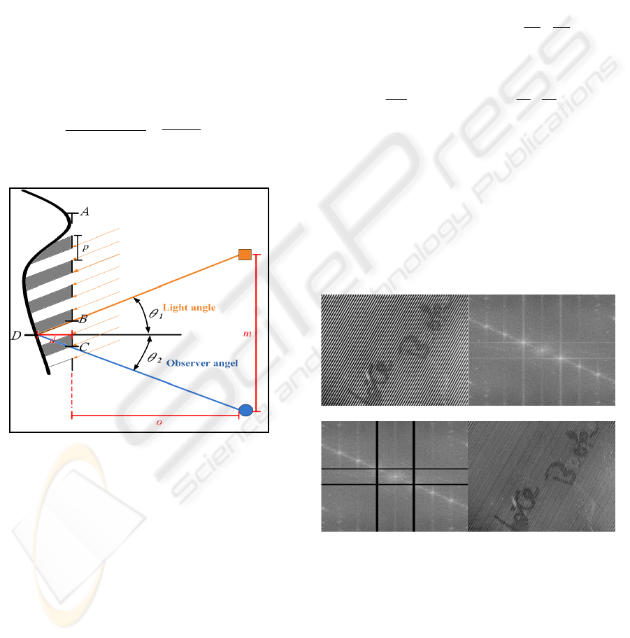
size can’t too thin or dense to produce diffraction
effects (Glassner, 1999).
From the observation, the overlapped Moiré of
two gratings of AC and AD were recognized
simultaneously. The number of AB straight stripes
has m lines and AD has n lines, then
mpAC = , npAB
=
NppnmABACBC =−
=
−= )(
)tan(tan
21
θ
θ
+= dBC
N: the number of Moiré fringe within the scope of
AC.
p: pitch of grating.
θ
1
: incidence of light.
θ
2
:Observation angle of image.
21
tantan
θθ
+
=
Np
d
m
oNp ×
=
(1)
d: Distance of a testing object and reference grating.
Figure 2: Enlargement of Shadow Moiré measurement
framework (Tran etc., 1996).
From the equation 2.1, each moiré fringe can be
calculated. It can be seen that each Moiré is a
contour, in which we can label each moiré fringe in
order to facilitate the depth calculation of the
measurement surface.
2.2 The Image Processing Methods
2.2.1 Remove the Reference Grating Stripes
In the Moiré image, if the reference grating pitch is
too large then the reference grating stripes will be
very obvious, which is not the required information.
The impact of stripes on the images are
comprehensive and can be seen as a periodical
signal in the whole image. It must use a low pass
filter to remove (Batouche, 1992).
Suppose the original matrix is f (x , y), x and y
are matrix elements. Through Fourier transformed,
the output matrix is F(u ,v). Suppose index the
matrix is M×N, the x-index ranges are from 0 to M-1
and the y-index ranges are from 0 to N-1. Equations
2.2 and 2.3 are the two-dimensional discrete Fourier
transformation formula:
∑∑
−
=
−
=
⎥
⎦
⎤
⎢
⎣
⎡
⎟
⎠
⎞
⎜
⎝
⎛
+−=
1
0
1
0
2exp),(),(
M
x
N
y
N
yu
M
xu
iyxfvuF
π
(2)
the reversed transformation is
∑∑
−
=
−
=
⎥
⎦
⎤
⎢
⎣
⎡
⎟
⎠
⎞
⎜
⎝
⎛
+=
1
0
1
0
2exp),(
1
),(
M
x
N
y
N
yu
M
xu
ivuF
MN
yxf
π
(3)
Figure 3 (a) is a stripe of its Fourier transformed
images shown in Figure 3 (b), which could be
observed out of several star shapes. The more close
of the distance represents more thin and dense of
straight line, that is the frequency is more higher.
Reversely, the far of the distance represents the
frequency is low and the pitch of straight stripes is
larger. is shown in Figure 3 (c) is the image after
processing by a notch filter . The straight-line stripes
have been removed, shown in Figure 3 (d).
(a) (b)
(c) (d)
Figure 3: Fourier transformed with the notch filter image
processing.
A template mask scanning on the image with the
adjacent grayscale calculates the new grayscale
value. If it uses a linear function to obtain the mask,
this mask can also be called as a linear filter
(McAndrew, 2004).
Too much detail of images in the computer
vision on some specific pattern recognition will
DCNET 2010 - International Conference on Data Communication Networking
162
affect its results. To solve this problem, a low-pass
filter on the image will produce fuzzy results and
also can reduce the noise.
2.2.2 Enhance the Image Contrast
The contrast of a non-obviously image can be
enhanced through the expansion of gray-scale
distributions.
Using histogram equalization, assuming a gray-
scale image has L gray levels, in the histogram of
the i layer has n pixels, and assuming that all the
number of pixels are
110
...
−
+++=
L
nnnN
the gray-
level i can be replaced by Equation 2.4 (Lin, 2001):
()
1
...
10
−
⎟
⎠
⎞
⎜
⎝
⎛
+++
L
N
nnn
i
(4)
A clear contrasted black and white images will be
obtained.
2.2.3 Binarization
After the step of the image contrast enhancement,
the next step is the binary image process. The
required stripes and unnecessary image need to be
split. The change of gray-scale image will be
converted into black and white binary images. A
common method is to set a threshold value of gray-
scale images T to judge the grayscale value of each
pixel, shown as follows.
⎩
⎨
⎧
<
≥
=
Tyxg
Tyxg
yxg
),(,0
),(,255
),(
Sometimes, the brightness of image is not consistent.
A single threshold may not be fully extracted the
images. The images can be cut to different blocks
and each image block can have different setting of
threshold value.
2.2.4 Thinning
The Zhang-Suen iterative algorithm was used to
process the thinning (Zhang & Fu, 1984).
1. Odd-iteration was used to remove the right,
bottom and upper-left corner pixels.
2. Even-iteration was used to remove the left, top
and bottom right corner pixels.
However, there is certain condition should be
considered. There is one neighboring pixel which
may be the endpoint of framework and can’t be
removed. if there are 7 or more neighboring pixels,
then it should remove the image object which
probably can destroy the shape of image.
After the thinning step, it should remove the four-
side line to get a contour line graph. The next section
will be the actual measurement results and establish
the three-dimensional graphic.
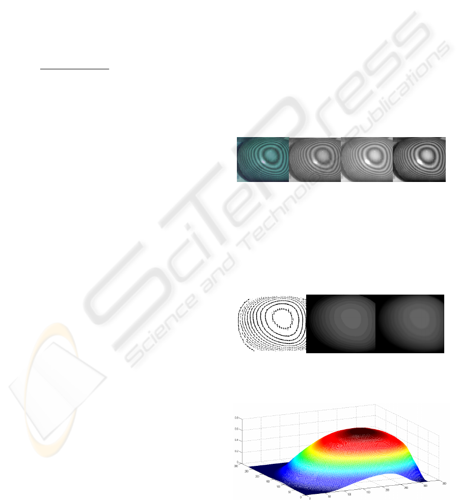
3 EXPERIMENTAL RESULTS
The pitch of reference grating is 1mm (p = 1mm),
light source is from θ
1
= 45 ° to project, and the
observation is from θ
2
= 0 ° to observe, shown in
Figure 4 which is the extracting image of the Moiré.
Through Equation 3.1 calculating the d=1N(mm), it
represents that there is a depth change of 1 mm in
each pixel. The image area was cut appropriately
and the color image was converted into grayscale for
each pixel RGB (www.mathworks.com, 2009).
Gray=0.299×R + 0.587×G + 0.114×B (5)
Cutting the region of interest image and filtering
the reference grating stripes, shown in Figure 4.
(a) (b) (c) (d)
Figure 4: Capture images (a) original image (b) 8-bit
grayscale (c) filtering the grating stripes (d) contrast
enhancement.
After binarization of the image, the unneeded
parts were cut or manual removed, shown as Figure
5(a) Marking on the Moiré lines, Figure 5(b) fill in
the different gray values.
(a) (b) (c)
Figure 5: Remove the unwanted unneeded parts and fill in
the gray-scale value.
Figure 6: Three-dimensional graphic rebuit.
3D OBJECT MEASUREMENT BY SHADOW MOIRÉ
163
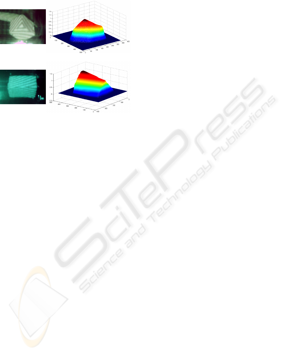
(a1) (a2)
(b1) (b2)
Figure 7: (a1) (b1) original photos (a2) (b2) three-
dimensional measurement results.
4 CONCLUSIONS
This research applies shadow Moiré to measure the
shape of the mouth. It can freely adjust the different
grating pitch, light sources and different image
grabbing angle to get different resolutions. The more
the density of the grating is, the higher the resolution
is. However, when the shadow stripe on the object is
not obvious, it will increase the difficulty to process.
If the light is not uniform while projecting, aperture
and shutter exposure are not all the same. The
images can’t be processed by a fixed step of the
camera operation. Sometimes it requires manual
adjustment and handling. In the future, in order to
increase its feasibility of projection Moiré in the
experiment, it can also build more samples of the
moving objects. The further study also needs to use
the measured information matching with the 3D
graphic design software to create animation models.
ACKNOWLEDGEMENTS
The author would like to show appreciation that this
work was supported by the National Science
Council of Taiwan, ROC under Grant No. NSC-96-
2221-E-167-026-MY3.
REFERENCES
Fu, G. B., Precise Electro-Optic Technology, 1997, Taipei,
Kau-Li Book Co. (In Chinese).
Glassner, A., 1999. Glassner's Notebook: Recreational
Computer Graphics, IEEE Computer Graphics and
Applications, Morgan Kaufmann.
Tran, A. T., Lee, J. J., Zhang, K., Lo, Y. H., 1996.
“Ultrafine Motion Detection of Micromechanical
Structures Using Optical Moiré Patter”, IEEE
Photonics Technology Letters, vol. 8, no. 8, pp.1058-
1060.
Batouche, M., 1992. “A Knowledge Based System for
diagnosing spinal deformations: Moiré Pattern
Analysis and Interpretation.” CRIN/CNRS-INRIA
Lorraine Campus scientifiquen Vandoeuvre,
pp. 591-594, France.
McAndrew, A., 2004. Introduction to Digital Image
Processing with MATLAB, Thomdon Learning
Company.
Lin, C. S., 2001. Digital Signal-Image and Voice
Processing, Taipei, Chan-Hwa Technology Book Co.
(In Chinese).
Zhang, S, Fu., K, 1984. “A Thinning Algorithm for
Discrete Binary Images.” Proceedings of the
International Conference on Computers and
Application. pp.879-886, Beijing, China.
Convert RGB image or colormap to grayscale. http://
www.mathworks.com/access/helpdesk/help/toolbox/i
mages/rgb2gray.html (retrieved date 07-19-2009)
DCNET 2010 - International Conference on Data Communication Networking
164
