
MANAGING DATA DEPENDENCY CONSTRAINTS THROUGH
BUSINESS PROCESSES
Joe Y.-C. Lin and Shazia Sadiq
School of Information Technology & Electrical Engineering, The University of Queensland, Brisbane, Australia
Keywords: Business Process Management, Data Flow, Constraint Modelling.
Abstract: Business Process Management (BPM) and related tools and systems have generated tremendous advantages
for enterprise systems as they provide a clear separation between process, application and data logic. In
spite of the abstraction value that BPM provides through explicit articulation of process models, a seamless
flow between the data, application and process layers has not been fully realized in mainstream enterprise
software, thus often leaving process models disconnected from underlying business semantics captured
through data and application logic. The result of this disconnect is disparity (and even conflict) in enforcing
various rules and constraints in the different layers. In this paper, we propose to synergise the process and
data layers through the introduction of data dependency constraints, that can be modelled at the process
level, and enforced at the data level through a (semi) automated translation into DBMS native procedures.
The simultaneous and consistent specification ensures that disparity between the process and data logic can
be minimized.
1 INTRODUCTION
The evolution of business software solutions has
seen a number of architectural generations. For the
last several years, business process management
(BPM) has secured a leading position in enterprise
systems. A process enabled enterprise system will
typically have a three-tier architecture consisting of
data, application and process layers.
Just as the DBMS provided a means of
abstracting application logic from data logic, the
business process management systems (BPMS)
provided a means of abstracting coordinative
process logic from application logic. Every
generation has provided additional functionality
through supporting systems.
A clear separation of Process, Business, Data,
and Presentation aspects of enterprise systems with
minimal overlap can be observed in current process-
enabled systems.
Furthermore, application components have
minimal direct awareness of one another and also
have minimal direct awareness of “where and how”
they are being utilized in BPM layer. BPM takes the
primary responsibility to achieve business objectives
through configuration, coordination, collaboration,
and integration of application components.
In spite of the abstraction value that BPM
provides through explicit articulation of process
models, a seamless flow between the data,
application and process layers has not been fully
realized in mainstream enterprise software, thus
often leaving process models disconnected from
underlying business semantics captured through data
and application logic. The result of this disconnect is
disparity (and even conflict) in enforcing various
rules and constraints in the different layers.
In this paper, we propose to synergise the
process and data layers through the introduction of
data dependency constraints. These constraints can
be modelled at the process level, thus providing the
benefits of abstraction and clarity of business
semantics. At the same time, we propose an
automated translation of these constraints into
DBMS native procedures. The simultaneous and
consistent specification ensures that disparity
between the process and data logic can be
minimized.
The remaining paper is organized as follows: We
first present a detailed discussion on related work in
section 2, which encompasses data dependency
constraints in general as well as managing of data
52
Y.-C Lin J. and Sadiq S. (2010).
MANAGING DATA DEPENDENCY CONSTRAINTS THROUGH BUSINESS PROCESSES.
In Proceedings of the 12th International Conference on Enterprise Information Systems - Information Systems Analysis and Specification, pages 52-59
DOI: 10.5220/0002898000520059
Copyright
c
SciTePress

dependency and data flow in BPMSs. We will then
introduce in section 3, two types of data dependency
constraints that characterize certain notions of data
dependency in business processes. These are
presented within a typical architecture of a BPMS.
We will demonstrate that the constraints cannot be
easily modelled in current business process
modelling languages and will provide a discussion
on their properties. We present in section 4, an
automated translator of the constraints into DBMS
native procedure for constraint enforcement in the
data layer, and finally discuss the main contributions
and future extensions of this work in section 5.
2 RELATED WORK
Historically, one of the first successes in data
integrity control was the invention of referential
integrity enforcement in relational database systems
(Date 1981). The generality of this solution, based
on a formal definition of a class of constraints, made
this data management concept uniformly applicable
(independently from application domain), thus
eliminating large numbers of data integrity errors.
Since then, data dependency constraints have been
widely studied with many classes of constraints
introduced.
In (Fan et al. 2008) the authors proposed a class
of integrity constraints for relational databases,
referred to as conditional functional dependencies
(CFDs), and study their applications in data
cleaning. In contrast to traditional functional
dependencies (FDs) that were developed mainly for
schema design, CFDs aim at improving the
consistency of data by enforcing bindings of
semantically related values.
In this paper, we aim to extend the data
dependency constraints of process enabled systems
through the business process model. In general, the
process model is a definition of the tasks, ordering,
data, resources, and other aspects of the process.
Most process models are represented as graphs
mainly focussed on the control flow perspective of
activity sequencing and coordination, such as Petri
nets (Aalst & Hofstede 2000), (OMG/BPMI 2009),
(OMG 2009).
In addition, some process models (often in
scientific rather than business domain) focus on the
data flow perspective of the process, i.e. data-centric
approaches. The importance of a data-centric view
of processes is advocated in (Ailamaki et al. 1998)
and (Hull et al. 1999). In (Ailamaki et al. 1998), the
authors promote an “object view” of scientific
workflows where the data generated and used is the
central focus; while (Hull et al. 1999) investigates
“attribute-centric” workflows where attributes and
modules have states. Further, a mixed approach was
proposed by (Medeiros et al. 1995) which can
express both control and data flow. (Reijers et al.
2003) and (Aalst et al. 2005) uses a product-driven
case handling approach to address some concerns of
traditional workflows especially with respect to the
treatment of process context or data. (Wang &
Kumar 2005) proposed document-driven workflow
systems where data dependencies, in addition to
control flows, are introduced into process design in
order to make more efficient process design.
Another approach called the Data-Flow Skeleton
Filled with Activities (DFSFA) is proposed in (Du et
al. 2008) to construct a workflow process by
automatically building a data-flow skeleton and then
filling it with activities. The approach of DFSFA
uses data dependencies as the core objects without
mixing data and activity relations. (Joncheere et al.
2008) propose a conceptual framework for advanced
modularization and data flow by describing a
workflow language which introduces four language
elements: control ports, data ports, data flow, and
connectors. Their view of workflow's data flow is
specified separate from its control flow by
connecting tasks' data ports using a first-class data
flow construct. Also worth mentioning is the work
on data flow patterns (Russell et al. 2005), in
particular the internal data interaction pattern
namely Data-Interaction – Task to Task (Pattern 8).
It refers to the ability to communicate “data
elements” between one task instance and another
within the same case, and provides three approaches,
namely a) Integrated Control and Data Channels b)
Distinct Control and Data Channels c) No Data
Passing that uses a global shared repository. (Kunzle
& Reichert 2009) studies the activity-centered
paradigm of existing WfMS are too inflexible to
provide data object-awareness and discussed major
requirements needed to enable object-awareness in
process management systems.
Despite these contributions from research in
modelling data flow perspectives of business
process, widely used industry standard such as
BPMN will only show the flow of data (messages),
and the association of data artefacts to activities, that
is, it doesn’t express the data flow (logic) below the
Data Object level. It can be observed that data
artefacts can have interdependencies at a low level
of granularity which if not explicitly managed, can
compromise the integrity of the process logic as well
as corrupt underlying application databases. We
MANAGING DATA DEPENDENCY CONSTRAINTS THROUGH BUSINESS PROCESSES
53

propose to use concepts and contributions from
research in data integrity management through data
dependency constraints to overcome this limitation
in business process models. Our work is focussed on
a specific class of data dependencies, that have the
capacity to not only enrich the process model, but
also provide a means of enforcing the constraints
across all layers of the process enabled enterprise
system, namely process, application and data. The
next section details our approach.
3 DATA DEPENDENCY
CONSTRAINTS FOR PROCESS
MODELS
We present in Figure 1 a reference BPM architecture
to provide the background for managing data
dependency constraints through BPM. Our aim is to
demonstrate the above mentioned layers namely
Data logic, Business or Application logic and
Process logic within the architecture:
The Data logic components provide
repositories for business and corporate data as
well as documents, mails, content
management system data, etc.
The Business logic components provide
business application functionalities through
various type of application and the
coordination of these applications are through
the web-based tools provided by the BPM
Suite or via custom developed interface with
the BPM tools..
The BPM Suite provides the core BPM
functionalities which includes two main parts,
Business Modeller and Workflow Application
Service.
Figure 1: BPM reference architecture.
In Figure 1, it is worth to distinguish the
differences between Process Relevant Data and
Application Data. Process Relevant Data is used by
the Business Process Management System (in
addition to other uses) to determine the state
transitions of a process instance, for example pre-
and post-conditions, transition conditions, etc. Such
data may affect the choice of the next activity to be
chosen and may be manipulated by related
applications as well as by the process engine. On the
other hand, the Application Data is application
specific and strictly managed by applications
supporting the process instance. In terms of the data
flow pattern Data-Interaction – Task to Task in
(Russell et al. 2005), the Process Relevant Data
refers to the third category i.e. the use of a “Global
Shared Repository”.
In the context of the above architecture, we
propose to introduce the modelling and enforcement
of two classes of data dependency constraints though
the BPMS. We identify these as so-called Change
Dependency Constraint and Value Dependency
Constraint.
To understand the semantics behind the
constraints, consider the following scenario.
Figure 2: Example scenario.
Assuming a hotel booking system introduces
special booking rates to the process, where 3 specific
data elements entered in activity Select City, Select
Hotel, Check out are named A, B and C respectively.
Suppose we would like to specify a constraint that
ensures if A and B are entered in certain values, the
value of C would be pre-determined. For example, if
Date = “10/Mar/09” and “Hotel” = Hilton, then
Discount = 10%. This constraint would guarantee
the data quality of the applications associated with
the process is synchronized with the process
definition, as well as the ability to dynamically
modify the “condition values” without changing the
process definition. While the values do not dictate
the values of every instance, but rather options of the
possible combinations, the dashed line implies this
weak relationship. Current business process models
Select
City
A
B C
City Hotel Date Discount
Timestamp1
Timestam
p
2
Timestamp3
Timestam
p
4
processrelevant dataforprocessinstanceX
Brisbane
Brisbane
Brisbane
Brisbane
Hilton
Hilton
Hilton
10%
10%
10/Mar/09
10/Mar/09
Select
Hotel
Select
Date
Checkout
E
Reward$
$10
$10
$10
$5
Confir‐
mation
BookingFee
$5
E
D
F
Use
Reward$
User
Desktop
Authentication
Intranet
Web
Server
Internet
Web
Server
Portal
O
t
h
er
External
Apps.
BPMSuite
WorkflowApplicationService
BusinessModeller
UserWorklist
Business
Applicatio
Process
EnactmentEngine
Worklist
Handler
Process
Relevant
Data
Process
Modelling
Tool
AdministrationTool MonitoringAndAnalysis
Admin
User
Application
Database
Data
Repository
Data
Repository
Document
Server
Ma
il
Server
C
ontent
Management
Server
Doc
Data
Ma
il
Data
CMSData
Process
Repository
Process Business Data
Web
Browser
Interface
OtherBPMS
Interface
Legend
Don’tUse
Reward$
ICEIS 2010 - 12th International Conference on Enterprise Information Systems
54

do not have the feature to support the specification
of such “value dependency”.
Similarly we can observe that changes in data
values can also have dependencies. For example,
assume the user decides to spend his/her
membership reward point for further discount, the
system would automatically deduct the amount from
the balance at the checkout. This constraints
enforces the automatic calculation of Process
Relevant Data “Reward $”, we term such a
constraint as “change dependency”.
In the following discussion, we will provide a
means of specifying the constraints using a well-
known notion of data tableaus borrowed from
database integrity constraint management. The
tableaus allow us to specify constraints in a concrete
manner, as well reason with their properties.
However, we first need to present some background
concepts on process schema and instance, as well as
data tableaus.
Definition 1 (Process Schema). A tuple P = (N, C,
D, L, K) is called a process schema with:
- N is a set of finite Nodes. Each node n ∈ N has a
type T ⊆ E ∪ A ∪ G such that E ∪ A ∪ G, E ∩
A = φ, A ∩ G = φ, E ∩ G = φ,where E denotes
the set of Event types (e.g., Start, End, etc.) and
A denotes the set of Activity types (e.g. User,
Manual, Service, etc.) and G denotes the set of
Gateway types (e.g., AND-SPLIT(Fork), XOR-
SPLIT(Choice), AND-JOIN(Join), XOR-
JOIN(Merge) )
- C is a set of Connecting objects or Control Flow.
Connect Relation C ⊆ N
╳ N is a precedence
relation (note: n
src
.
→
n
dest
≡ (n
src
.
,
n
dest
) ∈ C )
- D is a set of process data elements. Each data
element d ∈ D has a type D where D denotes the
set of atomic data types (e.g., String, number,
etc.)
- L ⊆ N
╳ D is a set of data links between node
objects and data elements. For the purpose of
this research, we assume the link exists at the
point of node completion, i.e. the value of the
data elements equals the value stored in
database at the end of the activity (node).
- For each link l∈L, l can be represented by a pair
<n, d >
node[l] or n[l]=n where n∈N represent node of
l.
data[l] or d[l]=d where d∈D represent data
element of l.
- K:C TC(D) ∪ φ assigns to each control flow
an optional transition conditions where TC(D)
denotes the set of all valid transition conditions
on data elements from D
Definition 2 (Process Instance). A process instance
I is defined by a tuple (P
I
, NS
P
I
, V
P
I
)where:
- P
I
:= (N
I
, C
I
, D
I
, L
I
) denotes the process schema
of I which is determined during runtime, where
N
I
denotes the node set and C
I
denotes the
control flow set and D
I
denotes the data element
set and L
I
denotes the data elements link set.
- NS
P
I
describes node states of I: NS
P
I
:N
I
{Initial, Scheduled, Commenced, Completed }
- V
P
I
denotes a function on D
I
, formally: V
P
I
:
D
I
Dom
D
I
∪ {Undefined}. This means for each data
element d∈D
I
has a value either from domain
Dom
D
I
or an Undefined value which has not been
stored yet.
- In particular, we denote V[L
I
]
P
I
as the values of
data elements link sets of Process Instance P
I
,
which is a function on L
I
, formally:
V[L
I
]
P
I
: D
I
Dom
D
I
∪ {Undefined} and L
I
=N
I
╳
D
I
Definition 3 Data Tableau. A data tableau T
L
I
is a
tableau with all attributes in L’, referred to as the
value pattern tableau of L’
or V[L’], where for each l
in L’ and each tuple t ∈T
L
I
, t[l] is either a constant in
the domain Dom(d) of l, or an unnamed variable ‘
_‘.
- L’⊆ L, therefore the maximum number of
attributes in T
L
I
equals |L|.
- t[l] = ‘_’ means that the value can be anything
within Dom
d
∪ {Undefined}
- For example: a tableau can be presented as the
following
Tableau for Definition 3
<n
1
,d
1
> <n
2
,d
1
> <n
3
,d
1
>
- - -
10 10 10
This tableau implies that the value of d1 can be
anything within the Dom(d
1
) throughout n
1
to n
3
, but
if <n
1
,d
1
> = 10, then the values of d
1
at n
2
and n
3
must remain consistent.
3.1 Constraint Specification
Using the notion of data tableaus from above, we
can specify value and change dependency
constraints as below in Figure 3 and 4 respectively.
In Figure 3 a data dependency is defined through
the value relationship between multiple data items.
The Tableau T represents the conditional values
Hotel, Date and Discount at Task SelectHotel,
→
→
→
→
MANAGING DATA DEPENDENCY CONSTRAINTS THROUGH BUSINESS PROCESSES
55

SelectDate and Checkout respectively. The Tableau
suggests a conditional rule such that if Hotel equals
to Hilton and Date equals to 10/Mar/2009, then the
Discount will be 10%. Otherwise the data will not be
accepted. In this example, instance 1 does not satisfy
this rule therefore the data is invalid.
Figure 3: Value dependency.
In Figure 4 another type of data dependency is
given, which defines the conditions under which a
data value can be changed. The example below
defines the conditional values of Reward$ at
“SelectDate”, “Use Reward$”, “Don’t Use Reward$”
and “Checkout” respectively. Since the Tableau
suggests a conditional rule such that if Reward$ at
SelectDate equals to $M and if the path “Use
Reward$” is taken and BookingFee$ equals to $F
then the Reward$ at Checkout would equal to $(M-
F). In this example, instance 4 does not satisfy this
rule therefore the data is invalid.
Figure 4: Change dependency.
Together, the above two examples demonstrate a
new type of constraint which we collectively refer to
as “Conditional Data Dependency”. We define a
Conditional Data Dependency as below:
Definition 4 (Conditional Data Dependency or
CDD). A conditional data dependency φ is a pair
(F:X Y, T), where
- X, Y are sets of links X,Y∈L,
- F:X Y is a standard Data Link Dependency,
F ⊆ L
╳ L is a precedence relation (note: l
from
→
l
to
≡ (l
from
., l
to
) ∈ F )
- alternatively, we can represent a data link
dependency f as <n
i
, d
p
><n
j
, d
q
>, where
node[l
from
] = n
i
, data[l
from
] =d
p
, node[l
to
]=n
j
,
data[l
to
]=d
q
.
-
T is a tableau with all attributes in X and Y,
referred to as the pattern tableau of φ. Where for
each l in X or Y and each tuple t∈ T, t[l] is either
a constant in the domain Dom(d) of l, or an
unnamed variable ‘_‘.
In particular, we define:
Definition 5 (Value Dependency Constraint). A
Value Dependency Constraint φ is a pair (F:X Y,
T), where
For all <n
i
, d
p
>, … <n
j
, d
q
> in X and Y, n
i
≠ n
j
implies d
p
≠ d
q
This means, the Tableau T defines the
relationships of value of multiple data elements
Definition 6 (Change Dependency Constraint). A
Change Dependency Constraint φ is a pair (F:X
Y, T), where
For all <n
i
,d
p
>, … <n
j
, d
q
> in X and Y, n
i
≠ n
j
implies d
p
= d
q
This means, the Tableau T defines the changes
of value of the same data element
3.2 Constraint Analysis
We observe that the constraint specification exhibits
certain properties namely Subset, Transitivity,
Union, Decomposition and Pseudo transitivity.
Understanding the properties is essential to provide a
non-redundant and conflict-free specification.
Although it is not the aim of this paper to present a
detailed analysis of the constraints or verification
algorithms, we present below a summary of the
properties in order to, better understand the
semantics of the constraint specification.
Subset. One Conditional Data Dependency can
subsume another. Given two CDDs, F
1
:[X
1
Y
1
],T
1
and F
2
: [X
2
Y
2
],T
2
, F
1
F
2
iff X
1
X
2
and Y
1
Y
2
,
and tuples t
2
T
2
, tuple t
1
T
1
such that t
1
t
2
Transitivity. Given two CDDs, F
1
:[X Y],T
1
and
→
→
→
→
→
→
→
→
SelectDate,Reward$ Confirmation,BookingFee$
Tableau T
Execution Data
Vali
d
Vali
d
Vali
d
Invali
d
Checkout,Reward$
$M $F $(M‐F)
SelectDate,Reward$
$10
Confirmation,BookingFee$
$5
Checkout,Reward$
$5
$10 N/A $10
$20 $5 $20
$20 $5 $15
Instance1
Instance2
Instance3
Instance4
Select
City
Select
Hotel
Select
Date
Checkout
E
Confir‐
mation
E
F
Use
Reward$
Don’tUse
Reward$
SelectHotel,Hotel
Hilton
SelectDate,Date Checkout,Discount
10/Mar/2009 10%
Tableau T
SelectDate,Date
Instance1
SelectHotel,Hotel CheckOut,Discount
Hilton 20%
ExecutionData
10/Mar/2009Instance2 Hilton 10%
10/Mar/2009
Invali
d
Vali
d
18/Mar/2009Instance3 Hilton 0%
Vali
d
10/Mar/2009Instance4 Sheraton 0%
Vali
d
Select
City
B C
Select
Hotel
Select
Date
Checkout
D
Confir‐
mation
Use
Reward$
Don’tUse
Reward$
ICEIS 2010 - 12th International Conference on Enterprise Information Systems
56
F
2
: [Y Z],T
2
, We can derive a F
3
:[X Z],T
3
such
that tuples t
2
T
2
tuple t
1
T
1
such that t
1
[Y] =
t
2
[Y]
Therefore, from the property of CDD
Transitivity, we can define a new operator which
merges two CDDs into one.
Merge. Given two CDDs, F
1
:[X
1
Y
1
],T
1
and
F
2
: [X
2
Y
2
],T
2
, F
1
F
2
= F3: [X
3
Y
3
], T
3
iff X
3
= X
1
X
2
and Y
3
= Y
2
and tuples t
3
T
3
tuple
t
1
T
1
and t
2
T
2
such that t
3
[X
3
] = t
1
[X
1
] and t
1
[Y
1
] =
t
2
[Y
2
] and t
3
[Y
3
] = t
2
[Y
2
]
Union. Given two CDDs, F
1
:[X Y],T
1
and F
2
: [X
Z],T
2
, We can derive a F
3
:[X YZ],T
3
such that
tuples t
3
T
3
tuple t
1
T
1
and t
2
T
2
such that t
1
[X]
= t
2
[X] = t
3
[X] and t
3
[YZ] = t
1
[Y]t
2
[Z]
Therefore, from the property of CDD Union, we
can define a new operator which merges two
CDDs into one.
Join. Given two CDDs, F
1
:[X
1
Y
1
],T
1
and F
2
:
[X
2
Y
2
],T
2
, F
1
F
2
= F3: [X
3
Y
3
], T
3
iff X
1
= X
2
= X
3
and Y
3
= Y
1
Y
2
and tuples t
3
T
3
tuple
t
1
T
1
and t
2
T
2
such that t
1
[X
1
] = t
2
[X
2
] = t
3
[X
3
] and
t
3
[Y
3
] = t
1
[Y
1
] t
2
[Y
2
]
3.3 Summary
To summarize the above, we are proposing a new
type of data dependency constraint to model
dependencies within process relevant data. We call
such constraint a “Conditional Data Dependency”.
The CDD extends the current process modelling
specification by introducing a tableau to specify the
data dependency. Such constraint allows us to define
business rules to ensure data integrity through the
process layer to data layer.
While the specification of the CDDs allows us to
specify additional data constraints, the correctness of
the specification is also important. A number of
conflicts may emerge into the constraint
specification namely a) Invalid Data Link Attributes,
b) Conflict between Data Link Dependency with
Control Flow, c) Conflict between the tuples within
the Tableau, d) Conflict between Data flow and
Control Flow, etc.
For example, Consider a CDD ψ1 = (<Select
Date, Date> → <Checkout, Discount>, T
1
), where T
1
consists of two pattern tuples (10/Mar/2009, 10%)
and (10/Mar/2009, 20%). Then there is no instance
Pi can possibly satisfy ψ1. Indeed, for any tuple t in
Pi, the first pattern requires if the date equals to
10/Mar/2009, the discount will be 10%, which is
contradictory to the second pattern value 20%. Such
conflict is a typical conflict between the tuples
within the Tableau. Since it is not the scope of this
paper to discuss the methods for detecting and
resolving these constraint conflict problems, we
refer the works in (Sun et al. 2006) (Fan et al. 2008)
which can be used as a road map for implementation
of the verification algorithms. Design of specific
verification algorithms for the proposed constraints
is also part of our future work.
In the remaining paper we assume that a non-
redundant and conflict-free constraint specification
is available to the BPM system in the form of a data
tableau.
4 IMPLEMENTATION AND
EVALUATION
In this section we would like to demonstrate how a
proof of concept can be built for the above approach.
The objective is to demonstrate the specification of
the constraints at the process level, and enforcement
at the data level. We present the proof of concept
through a light weight implementation of a
workflow engine Chameleon built using MS
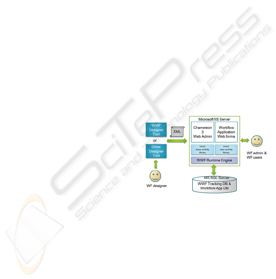
Windows Workflow Foundation (WWF). Figure 5
shows an overview of the Chameleon 3 architecture.
Figure 5: Chameleon 3 architecture.
It can be observed that the architecture is derived
from the reference BPM Suite we mentioned
previously in section 3. The Chameleon 3 Process
Modelling Tool is built based on the Windows
Workflow Foundation Designer Tools with extended
functionality. One of the most useful features of
Windows Workflow Foundation technology is that it
allows us to implement customized User Activity
types which enable us to implement the activities to
include extra properties and functionalities; such
extension allows us to access the underlying
Application Data and Process Relevant Data at the
modelling level. At design time, the WWF GUI
process designer tool has the access to any pre-built
→→
→
→→
→
→→
→
→→
MANAGING DATA DEPENDENCY CONSTRAINTS THROUGH BUSINESS PROCESSES
57
User Activity library we implement. We then use the
designer tool to create the process model and export
the process definition to an XML like language
called XOML. This process definition will then be
imported into the Chameleon Suite by using the
Web Admin tool hosted by Microsoft IIS Server.
The WWF services interpret the XML process
definition and stores the model as a process template
by a Process Repository database hosted by
Microsoft SQL Server. At runtime, the Admin User
creates and manages instances which the engine
provides supporting scheduling services for
persisting a workflow’s state, handling transactions
and also provides other services, such as
mechanisms for communicating with software
outside the workflow. The Workflow Users then use
the web interfaced Chameleon Workflow
Application and perform tasks on the Application or
Web forms corresponding to the work items on their
worklists.
In order to support the specification and
implementation of the proposed Conditional Data
Dependency, we developed the following
enhancement to Chameleon 3 architecture.
1. A Conditional Data Dependency Designer Tool
that uses an intuitive user interface for
specifying the constraint. This tool is an Add-
On to the existing WWF Designer that can
capture the constraints as tableaus as shown in
the previous section and then exported to the
required XML format.
2. An automatic translator to convert the specified
CDDs into rules in XML format and
subsequently insert the WWF built-in “Policy
Activity” into the XML file before importing
the model to the Chameleon Suite.
3. We present a simple procedure to translate the
CDD constraint to WWF native rule set as
follows:
begin
For each tuple in Tableau T
Writeln(If )
For each data value in X
Writeln(dp = Vp)
If not last value in X
Writelin( and)
End If
End For
Writeln(Then )
For each data value in Y
Writeln(dq = Vq)
If not last value in Y
Writelin( and)
End If
End For
End For
End.
4. The above procedure generates a WWF native
rule which can be processed by the WWF service.
This service automatically generates the underlying
data validation codes; hence the data integrity is
enforced at runtime as intended.
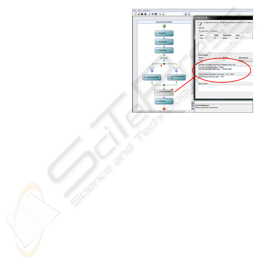
Figure 6 shows an example of the translation of
the Value Dependency described in Figure 3 which
generates a rule set for native WWF “Policy
Activity”. A policy activity is simply a
programmatic check for “If” condition “Then”
executes a specified “Action”.
Figure 6: WWF Rule Set for Value Dependency.
5 CONCLUSIONS
One of the biggest challenges in current large scale
enterprise systems is overcoming the growing
disconnect and consequent disparity in various parts
of the system. In this paper, we have attempted to
address the disparity in data integrity constraints that
may arise due to a disconnect between business
process models and underlying databases and related
applications. We have provided a means of
specifying two types of data dependency constraints
on process relevant data. Further we have provided a
proof of concept on how the constraint specification
can be utilized simultaneously at the process as well
as data level thus minimizing the opportunity for
disparity between them.
Although we briefly mentioned in this paper the
importance of the analysis and verification of the
constraints, ensuring correctness of the specification
(i.e. non-redundant and conflict-free) remains an
interesting and challenging extension of this work.
We also envisage further extension of the
ICEIS 2010 - 12th International Conference on Enterprise Information Systems
58

prototype implementation, namely Chameleon 3, to
include a smart CDD builder.
REFERENCES
Aalst, W. M. P., Hofstede, A. H. M., 2000. Verification of
workflow task structures: A Petri-net-based approach.
Information Systems, vol. 25(1) pp. 43–69.
Aalst, W. M. P., Weske, M., Grünbauer, D., 2005. Case
handling: a new paradigm for business process support.
Data and Knowledge Engineering 53, 129–162.
Ailamaki, A., Ioannidis, Y., Livny, M., 1998. Scientific
workflow management by database management. In
Proc. Int. Conf. on Statistical and Scientific Database
Management, pp.190-199.
Date, C. J., 1981. Referential Integrity. In Proc. of 7th Int.
Conf. on VLDB, September 9-11, 1981, Cannes,
France. pp.2-12.
Du, N., Liang, Y., Zhao, L., 2008. Data-flow skeleton
filled with activities driven workflow design. In Proc.
of 2nd Int. Conf. on Ubiquitous Information
Management and Communication. pp. 570-574.
Fan, W., Geerts, F., Jia, X., Kementsietsidis, A., 2008.
Conditional Functional Dependencies for Capturing
Data Inconsistencies. ACM Transaction on Database
Systems, Vol.33, No. 2, Article 6.
Hull, R., Llirbat, F., Simon, E., Su, J., Dong, G., Kumar,
B., Zhou, G., 1999. Declarative workflows that
support easy modification and dynamic browsing. In
Proc. Int. Joint Conf. on Work Activities Coordination
and Collaboration, pp. 69-78.
Joncheere, N., Deridder, D., Straeten, R., Jonckers, V.,
2008. A Framework for Advanced Modularization and
Data Flow in Workflow Systems. In Proc.of the 6th
Int. Conf. on Service-Oriented Computing, pp. 592-
598.
Kunzle, V., Reichert, M., 2009. Towards Object-aware
Process Management Systems: Issues, Challenges,
Benefits. In Proc. 10th Int'l Workshop on Business
Process Modeling, Development, and Support
(BPMDS'09), June 2008, Amsterdam, The
Netherlands. Springer, LNBIP 29, pp. 197-210
Medeiros, C., Vossen, G.,Weske, M., 1995. WASA: a
workflow-based architecture to support scientific
database applications. In Revell, N., Tjoa, A.M. (eds.)
DEXA 1995. LNCS, vol. 978, Springer, Heidelberg.
Object Management Group, 2009. Unified Modelling
Language, http://www.uml.org/
Object Management Group/Business Process Management
Initiative, 2009. Business Process Modelling Notation,
http://www.bpmn.org/
Reijers, H., Limam, S., and W.M.P. van der Aalst.
Product-based Workflow Design. Journal of
Management Information systems, 20(1): 229-262,
2003
Russell, N., Hofstede, A. H. M., Edmond, D. Aalst, W. M.
P., 2005. Workflow Data Patterns: Identification,
Representation and Tool Support. In Proc. of the 24th
Int. Conf. on Conceptual Modelling, vol 3716 of
LNCS, pp 353-368. Springer-Verlag, Berlin
Sun, S., Zhao, J., Nunamaker, J., Sheng, O., 2006.
Formulating the Data-Flow Perspective for Business
Process Management. Information Systems Research
vol. 17(4), pp. 374-391.
Wang, J., Kumar, A., 2005. A framework for document-
driven workflow systems. In Proc. Business Process
Management 2005(BPM2005), pp. 285–301.
MANAGING DATA DEPENDENCY CONSTRAINTS THROUGH BUSINESS PROCESSES
59
