DECOMPOSITION OF A 3D TRIANGULAR MESH INTO
QUADRANGULATED PATCHES
Roseline B
´
eni
`
ere, G
´
erard Subsol, William Puech
LIRMM, Univ. Montpellier 2, CNRS, 161 rue Ada, 34392, France
Gilles Gesqui
`
ere
LSIS, Aix-Marseille University, CNRS, IUT, BP 90178, 13637 Arles Cedex, France
Franc¸ois Le Breton
C4W, 219 rue Le Titien 34000 Montpellier, France
Keywords:
Remeshing, Quadrangular mesh, Quads quality, Parametrization.
Abstract:
In this paper we present a method to decompose a 3D triangular mesh into a set of quadrangulated patches.
This method consists in merging triangles to obtain quads. The quads are then grouped together to compose
quadrangulated areas and patches. Unlike many methods of remeshing, this method does not move the vertices
of the original triangular mesh. Quadrangulated patches extracted can then be used as a support of a parametric
function or of a subdivision scheme.
1 INTRODUCTION
In Computer Aided Design (CAD), numerical calcu-
lation or simple data exchange, it may be necessary
to discretize a 3D object to obtain a triangular mesh.
However, for many applications, a parametric repre-
sentation of these objects must be found. This topic
has been studied for many years. One way to solve
this problem is to calculate quadrangulated patches
which are then used to support parametric surfaces,
as shown in (Krishnamurthy and Levoy, 1996).
However, finding quadrangulated patches may be
useful for other applications. Thus (Arden, 2001)
shows the importance of these patches to use subdi-
vision methods, as the Catmull-Clark algorithm (Cat-
mull and Clark, 1978). The decomposition into quad-
rangulated patches can also be used for Finite Ele-
ments methods (Frey and George, 1999). Finally, in
the context of reverse engineering where we want to
find a CAD model composed of parametric surfaces,
searching such patches is essential (Bommes et al.,
2009a).
This paper is focused on this problem with the
three following constraints:
• The original vertex positions of the 3D triangu-
lar mesh must be preserved and new vertex must
not be added. We assume indeed that these po-
sitions were determined by metrology, or were
computed directly from discretized CAD models
or were generated by numerical computation.
• The edges of the quadrangulated mesh must be
derived from the triangulated mesh (see Figure
1(b)). This ensures that the final mesh will not
contain any incoherent junction, like, for exam-
ple, a T-junction where two edges cut themselves
in a point which is not a vertex of the mesh.
• The quadrangulated mesh must be decomposed
into patches which are rectangular grids with the
same number of rows for each column (see Figure
1(c)). This will then allow us to encode the object
in a standard format used in CAD as IGES (Initial
Graphics Exchange Specification).
A study of existing methods is proposed in Section
2 and shows some of their limitations. A new method
of decomposition into quadrangulated patches is pre-
sented in Section 3. Some results are shown in section
4, and future work is explored in Section 5.
96
Bénière R., Subsol G., Puech W., Gesquière G. and Le Breton F. (2010).
DECOMPOSITION OF A 3D TRIANGULAR MESH INTO QUADRANGULATED PATCHES.
In Proceedings of the International Conference on Computer Graphics Theory and Applications, pages 96-103
DOI: 10.5220/0002833900960103
Copyright
c
SciTePress
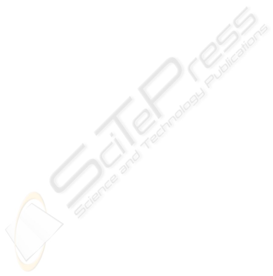
(a) (b) (c)
Figure 1: Extraction of quadrangulated patches: a quadran-
gulated mesh is computed from the triangulated mesh (b).
The quadrangulated mesh is then decomposed into patches
(c).
2 PREVIOUS WORK
We choose to classify the methods for creating a
quadrangulated mesh from a triangulated mesh into
the three following classes.
2.1 The Remeshing Algorithms
In these methods, the position of the vertices are
not preserved. The idea of quadrangulated remesh-
ing is not recent (see for example (Hormann and
Greiner, 2000)) but new methods called “Quad dom-
inant remeshing” have emerged these last years. In
2003, Alliez and al. (Alliez et al., 2003) propose to
compute the principal directions at each regular point
of the surface. The curvature lines which are the in-
tegral lines of the principal directions allow to draw a
quadrangulated grid on the surface. This method has
been extended and for example, Dong and al. pro-
posed to use harmonic functions (Dong et al., 2005).
A synthesis of these methods is presented in (Alliez
et al., 2007) and recent algorithms can be found in
(Bommes et al., 2009b), (Lai et al., 2009), (Dong
et al., 2006) or (Huang et al., 2008). Notice that
many papers mention the T-junction problem which
requires a post-processing to avoid inconsistencies in
the resulting meshes.
2.2 The Advancing Front Algorithms
The most representative method is Q-Morph (Owen
et al., 1998). The idea is to propagate the construc-
tion of quads from the outlines to the center of the
triangulated mesh. The resulting quads are based on
the edges of the triangulated mesh. However, they are
smoothed and their vertices are not anymore similar
to the original ones. Furthermore, this method raises
some problems in the case of closed meshes and re-
cently a solution has been proposed (Miyazaki and
Harada, 2009). In this method, the authors segment
the mesh into areas, based on the vertex normals and
they apply the Q-Morph method to these areas.
2.3 The Merging Algorithms
These methods come from the numerical analysis
field. Their aim is to merge triangles of the mesh into
quads to perform numerical computing, in general by
Finite Element methods. Most of these algorithms
work only with 2D meshes but (Borouchaki et al.,
1997) presents a simple and modular presents for 3D
meshes. This method is based on triangle merging
with respect to a quality coefficient. As (Tarini et al.,
2010), we have adapted and developed this idea to ob-
tain the first step of our decomposition algorithm.
2.4 Conclusion
All these methods create quadrangulated meshes
which are not composed of the original vertices and
edges of the initial triangular mesh. Furthermore,
they do not lead to a direct and explicit decomposi-
tion into patches even if some methods as (Eppstein
et al., 2008) have been proposed.
In this paper, we present a straightforward method
that combines both steps: quadrangulation and de-
composition into patches.
3 OUR METHOD
In this section we describe a new method of decompo-
sition into quadrangulated patches which is composed
of three steps:
• a coefficient which defines the quality of a quad
created by merging two triangles is computed for
each pair of adjacent triangles;
• quadrangulated areas are then built by aggregat-
ing the quads according to values of the quality
coefficient;
• quadrangulated areas are then decomposed into
quadrangulated patches.
3.1 Quads Creation
The first step consists in creating quads based on the
triangulated mesh. These quads should be built using
only vertices and edges of the original mesh. A quad
is defined by merging two adjacent triangles. A trian-
gle can lead to the creation of up to three quads, one
by edge, so a choice should be made.
As in (Borouchaki et al., 1997), this choice should
be based on a quality coefficient computed for each
pair of adjacent triangles. In our method, we want to
give high priority to quads which are similar to planar
rectangles. In this case, each angle α
i
of the quad is
DECOMPOSITION OF A 3D TRIANGULAR MESH INTO QUADRANGULATED PATCHES
97
close to
π
2
and the dihedral angle φ between the two
triangles constituting the quad is close to π (see Figure
2). So, a quality coefficient Q can be defined by:
Q =
2π if φ < φ
min
1
4
4
∑
i=1
|
π
2
− α
i
| else .
(1)
Thus, this coefficient equals to the average differ-
ence between each angle and
π
2
. Thus a quad which is
similar to a rectangle will have a coefficient close to
0.
φ
α
3
α
4
α
2
α
1
(a)
φ
(b)
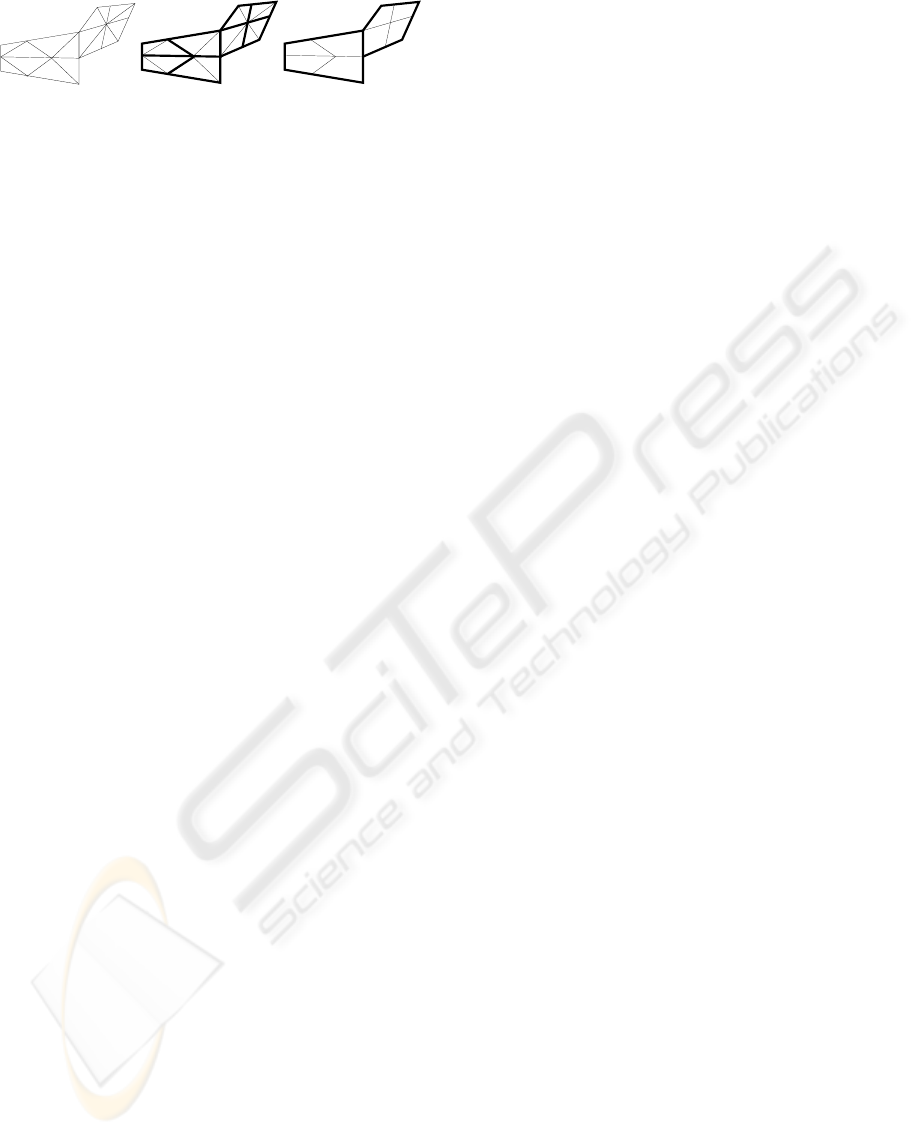
Figure 2: (a) The quality coefficient Q is computed with the
α
i
(in red) which are the angles at the quad vertices and the
dihedral angle φ (in blue). (b) A large dihedral angle and α
i
far from
π
2
implies a “bad” quality.
Moreover, if the dihedral angle is smaller than a
tolerance φ
min
, the quad will be flagged as “incorrect”
as in Figure 2(b). Similarly, the quads which have a
quality coefficient greater than the tolerance Q
max
are
not used to build quadrangulated areas.
3.2 Extraction of Quadrangulated
Areas
The aim of this step is to extract quadrangulated areas
using the quality coefficient presented in the previous
section.
In the first step, to initialize the process, the quad
with the best quality coefficient is chosen. The quad-
rangulated area is propagated iteratively by adding at
each step the quad having the best quality coefficient
among the neighborhood of the area in construction.
To find this quad, all potential quads containing an
adjacent triangle with an edge of the area outline are
examined. For example, in Figure 3(b), the hatched
triangles are examined to find the next quad of the
quadrangulated area.
The propagation is stopped when there is no
neighboring triangles anymore, or if the triangle is
isolated, or if the neighboring triangles can only cre-
ate quads with a quality coefficient larger than Q
max
.
When an area is finalized, a new area is initialized,
with the quad having the best quality coefficient in the
part of the triangulated mesh not used yet.
Initialization FinalizationStep n
(a)
(b)
(c)
Figure 3: Iterative extraction of a quadrangulated area: ini-
tialization with the quad having the best quality coefficient
(a); at each step a quad is added (b); the process stops when
there is no quad to be added anymore (c).
Thus from a triangulated mesh, one or more quad-
rangulated areas are obtained. For example, only one
quadrangulated area has been extracted from the mesh
in Figure 4. However, all triangles are not used, the
left triangles correspond to isolated triangles or tri-
angles which can only lead to quads with a quality
coefficient larger than Q
max
.
Figure 4: Extraction of a quadrangulated area from a trian-
gulated mesh. The left triangles do not enable to create a
quad having a good quality.
3.3 Decomposition into
Quadrangulated Patches
After the quadrangulated area process, a decomposi-
tion into sub-areas which are called “rectilinear poly-
gons” begins. For this purpose, a unique position is
assigned to each quad. This position consists in a line
number and a column number which will allow to de-
fine the rectilinear polygons.
The quad having the best quality coefficient is
chosen in the quadrangulated area. It is labeled with
the position (0, 0). Positions are then propagated to
its four neighbors, as in the Figure 5.
(1,1)
(0,1)
(1,0)
(0,1)
(0,0)
(0,0)
(1,0)
Initialization Step 1 Step n
(a)
(b)
(c)
(0,-1)
(-1,0)
(0,-1)
(1,-1)
(-1,1)
(0,0)
(-1,-1)
(-1,0)
Figure 5: Propagation of the position from the first quad to
its neighbors.
When a position is assigned to each quad, a recti-
linear polygon is defined using the positions to store
the quads at a correct place in a regular grid.
GRAPP 2010 - International Conference on Computer Graphics Theory and Applications
98
Creating the rectilinear polygon by assigning a po-
sition to each quad in relation to the position of its
neighbors can lead to ambiguities. Thus, the first cho-
sen quad in Figure 6 is quad 1, the positions of quads
2, 3, 4, 5 and 7 are easily deduced afterward. The
problem is with the quad 6 which would have both
the position (1, 2) as a neighbor “down” of the quad
5 and the position (0, 2) as a neighbor “up” of the
quad 7. Furthermore, these two positions are already
assigned. There will be another problem with quad
11 which has two different positions assigned, one as
the “right” neighbor of quad 8 and one as the “right”
neighbor of quad 9.
Such ambiguities occur when the vertices of the
quadrangulated area are not of valence 4. In the ex-
ample of Figure 6, a valence 3 vertex and a valence 5
vertex raise the position attribution problems.
8
9
11
12
10
31 5
2
(1,0)
4
7
(0,2)
(1,1)
(1,2)
6
(??,2)
(0,1)(0,0)
Valence 3
Valence 5
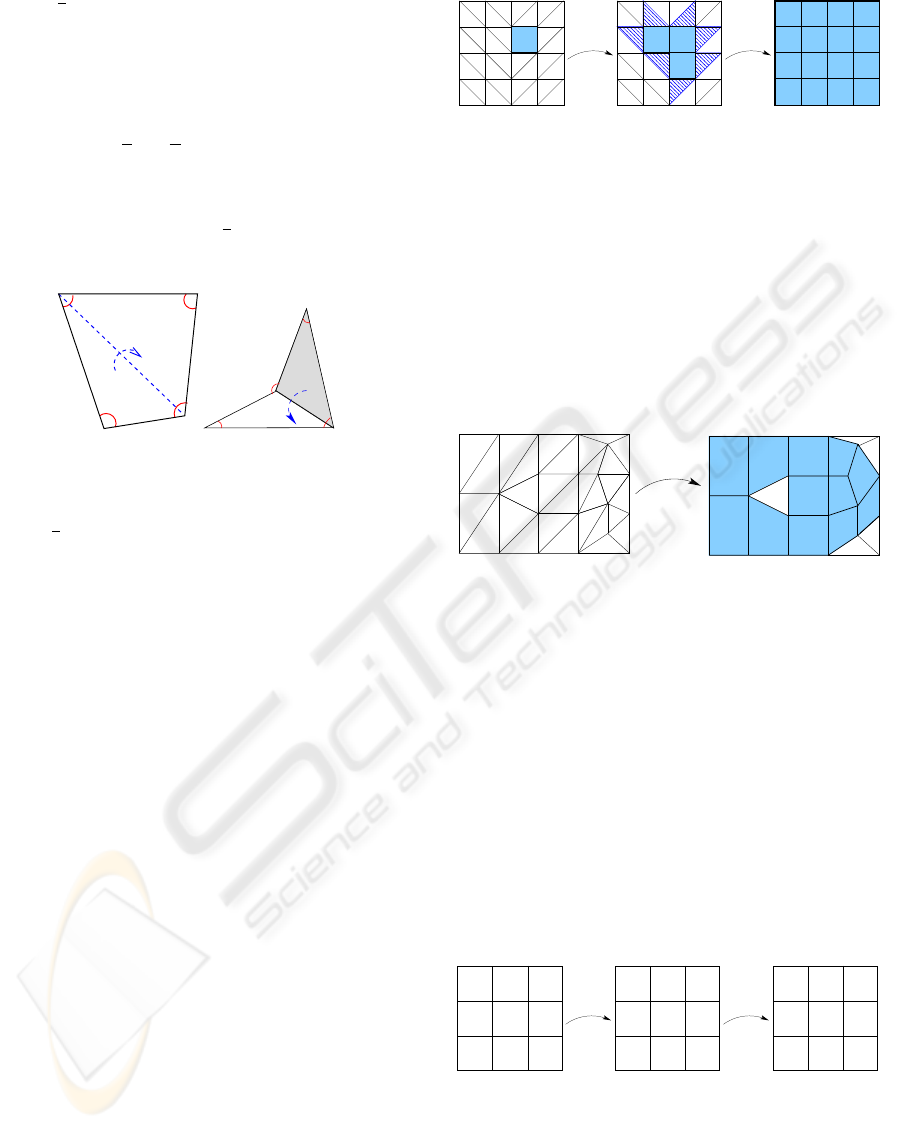
Figure 6: Decomposition into “rectilinear polygons” with
ambiguity positions with the quads 6 and 11.
To avoid this, some tests were added to check if
two quads have not the same position or if two po-
sitions are not assigned to the same quad. If any of
these cases occur, the rectilinear polygon is decom-
posed into two polygons. Thus the quadrangulated
mesh of Figure 6 is decomposed into three rectilinear
polygons as in Figure 7.
Rectilinear polygons containing only one quad are
not kept, like the rectilinear polygon with the single
quad 11 in Figure 7. Its two triangles remain then in
the triangulated mesh.
4
7
10
(0,0) (0,1) (0,2)
(0,3)
12
(0,4)
31
5
6
9
(0,0)
(0,1)
(0,2)
(1,3)
(0,3)
8
(1,2)
11
(0,0)
2
Figure 7: Decomposing the quadrangulated area into 3 rec-
tilinear polygons.
The last step enables to decompose the rectilin-
ear polygons into patches, which are rectangular grids
having the same number of lines for each column.
An iterative method is used to perform this. Ini-
tially, the patch with the greatest number of quads is
computed. The quads of the patch are removed from
the rectilinear polygon. A new patch with the great-
est number of quads can be then searched in the new
rectilinear polygon. The process is stopped when no
quad is left in the rectilinear polygon.
To find the patch with the greatest number of
quads in the rectilinear polygon, each quad of the rec-
tilinear polygon is examined. For a quad, all patches
having this quad at “left upper corner” are computed.
Such a computation of patches is based on browsing
along only two directions(→ and ↓), because the two
other directions were already examined by browsing
from the previous quads. The longest line (→) from
the quad is computed. Then, the number of lines hav-
ing the same length existing down (↓) is determined.
In Figure 8, from the quad q, the longest possible line
includes five quads, and lines of five quads are pos-
sible only on both lines. Finally, the patch with the
greatest number of quads among all patches computed
for each quad is selected.
q
Figure 8: Patch construction in a rectilinear polygon from
quad q.
Nevertheless, this method does not guarantee that
the number of patches is minimal at the end of the
process. Thus in Figure 9, extracting initially the
patch with the greatest number of quads (hatched
in blue), the rectilinear polygon is decomposed into
three patches whereas only two would be necessary
to cover the whole it.
Figure 9: Case where our method does not give an optimal
covering: we obtain three patches while two would be suf-
ficient.
However we decide to keep this simple approach
even if some methods exist to optimize the number of
patches dissecting the rectilinear polygon as for ex-
ample in (Soltan and Gorpinevich, 1993).
Finally, the three steps lead to three quadrangu-
lated patches, shown in Figure 10. Notice that a part
of the triangulated mesh is not used. This is due to
isolated triangles, quads of which Q > Q
max
, or quads
DECOMPOSITION OF A 3D TRIANGULAR MESH INTO QUADRANGULATED PATCHES
99
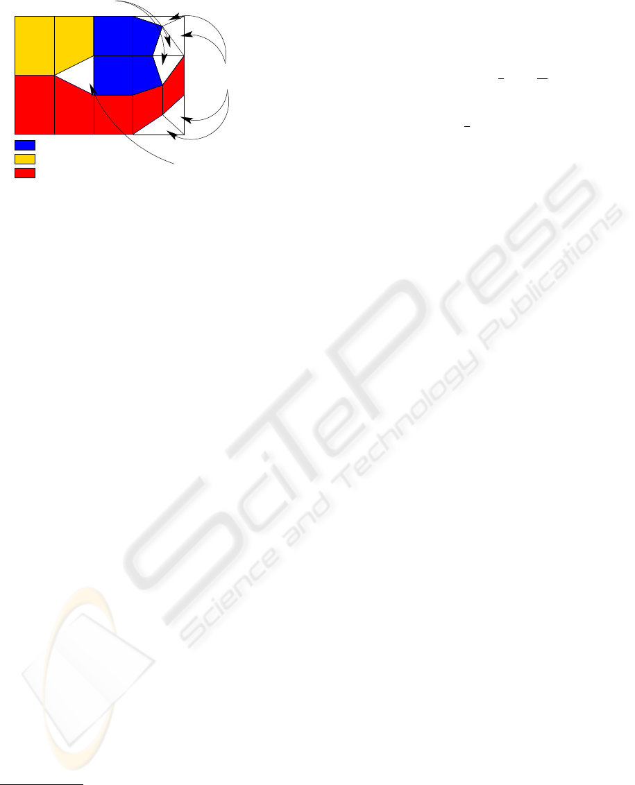
Quadrangle with
Triangle isolated
Patch extracted 1
Patch extracted 2
Patch extracted 3
Quadrangle isolated
bad quality
Figure 10: Decomposition into quadrangulated patches
from a triangulated mesh.
isolated during the creation of the rectilinear poly-
gons.
4 EXPERIMENTAL RESULTS
Our method has been implemented in the software 3D
Shop of the C4W
1
. This software gives efficient devel-
opment tools for 3D modeling and visualization
2
.
Figures 11 (Bunny), 12 (Face), 13 (Fandisk), 14
(Smurf
3
), 15 (CubeCylinders) and 16 (Torus) show
some results obtained on triangulated meshes coming
from various sources as CAD for CubeCylinders and
Torus, infography for Face and Smurf or 3D digitiza-
tion for Bunny and Fandisk. Each result is constituted
of the extracted quadrangulated patches (in blue) and
of remaining triangles (in green). Table 1 gives for
each mesh, the number of triangles, the number of ex-
tracted patches and the covering percentage that cor-
responds to the percentage of original triangles cov-
ered by quadrangulated patches.
On Bunny, Face and Fandisk, the quadrangulated
patches cover a large part of the mesh. That enables to
obtain a reduction factor between the triangle number
and the patch number which reaches 30. Effective
coding in CAD format based on the face concept (like
IGES) can be envisaged.
Nevertheless, some patches have a small size and
to cover 80% of the 5,590 triangles of the mesh Face,
335 patches are used. The decomposition of some
areas into small patches comes from a few triangles
or quads which are isolated and lead to decompose a
large potential patch into several smaller ones.
1
C4W is a company which develops innovative
CAD solutions and support this Ph.D. Thesis work
(http://www.c4w.com)
2
www.c4w.com/3d-cad-software.html
3
http://www.3dvalley.com/3d-models/characters
To avoid this and to create larger patches, we ex-
perimented different values for the parameters Q
max
and φ
min
because these thresholds may limit the prop-
agation process during the construction of quadran-
gulated areas. The values Q
max
and φ
min
were em-
pirically fixed to respectively
π
2
and
5π
6
, for all tests
except on the mesh Smurf.
For the mesh Smurf in Figure 14, the value Q
max
is fixed successively to
π
2
, π and 2π. The threshold
φ
min
has been modified in the last case to 2π: in this
case, all potential quads have been then considered.
Figure 14, with the mesh Smurf, which have 64,320
triangles, shows the patches evolution. Some areas
like the eyes, the hands or the shoulder contain many
triangles which are not used. The number of unused
triangles decreases when the thresholds are modified.
The number of patches decreases too and the cover-
ing percentage increases. These new results arises
because the patch shapes can change dramatically by
adding only one new quad as in Figure 14.
However, it is necessary to take care of the quad-
rangulated patches which can then contain some
quads with low quality. This may engender problems
to some applications, for example in numerical calcu-
lation. Moreover even when we set both thresholds
to 2π, there are always left triangles. Indeed, there
are triangles isolated in the quadrangulated areas con-
struction and quads isolated in the rectilinear poly-
gons construction. On the quadrangulated areas con-
taining many vertices which are not valence 4, these
quads can very be numerous and may lead to lots of
small rectilinear polygons.
Finally, we have tested our method on 3D simple
objects, like the union of a cube and two cylinders
(Figure 15). The result of the decomposition from
the mesh CubeCylinders, is satisfying because more
than 95% of the mesh is covered with only 21 patches
which corresponds to a reduction factor of more than
130. However in the case of a simply torus like Figure
16, our method finds one patch which covers 100%
of the object. The method is really adapted to CAD
meshes composed by simple primitives. In fact our
method has good result on the CAD mesh because
the discretization of the mesh has often a first step of
quadrangulation which was then triangulated.
5 CONCLUSIONS AND
PERSPECTIVES
In this paper, we have presented a method enabling to
decompose 3D triangulated meshes into quadrangu-
lated patches, without modifying the vertex position.
Our method is based on merging adjacent triangles to
GRAPP 2010 - International Conference on Computer Graphics Theory and Applications
100
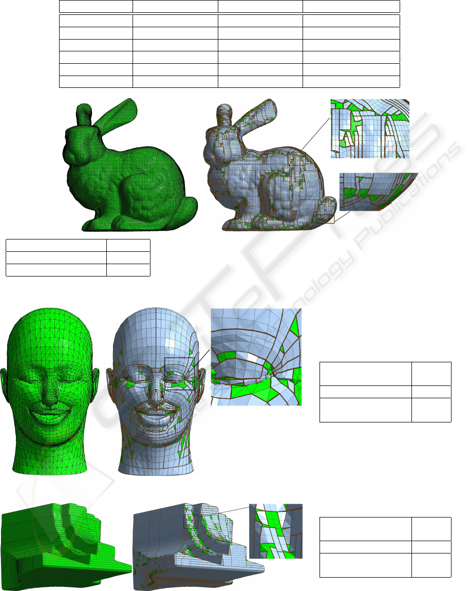
Table 1: Results on different 3D triangular meshes.
Mesh Triangles in mesh Extracted patches Covering percentage
Bunny 69,451 1,932 89.98%
Face 5,590 335 80.32%
Fandisk 23,964 720 88.66%
Smurf 64,320 931 91.39%
CubeCylinders 2,608 21 95.47%
Torus 9,384 1 100%
Triangles in the mesh 69,451
Extracted patches 1,932
Covering percentage 89.98%
Figure 11: Original mesh and result for: Bunny.
Triangles in the
mesh
5,590
Extracted patches 335
Covering percent-
age
80.32%
Figure 12: Original mesh and result for: Face.
Triangles in the
mesh
23,964
Extracted patches 720
Covering percent-
age
88.66%
Figure 13: Original mesh and result for: Fandisk.
DECOMPOSITION OF A 3D TRIANGULAR MESH INTO QUADRANGULATED PATCHES
101
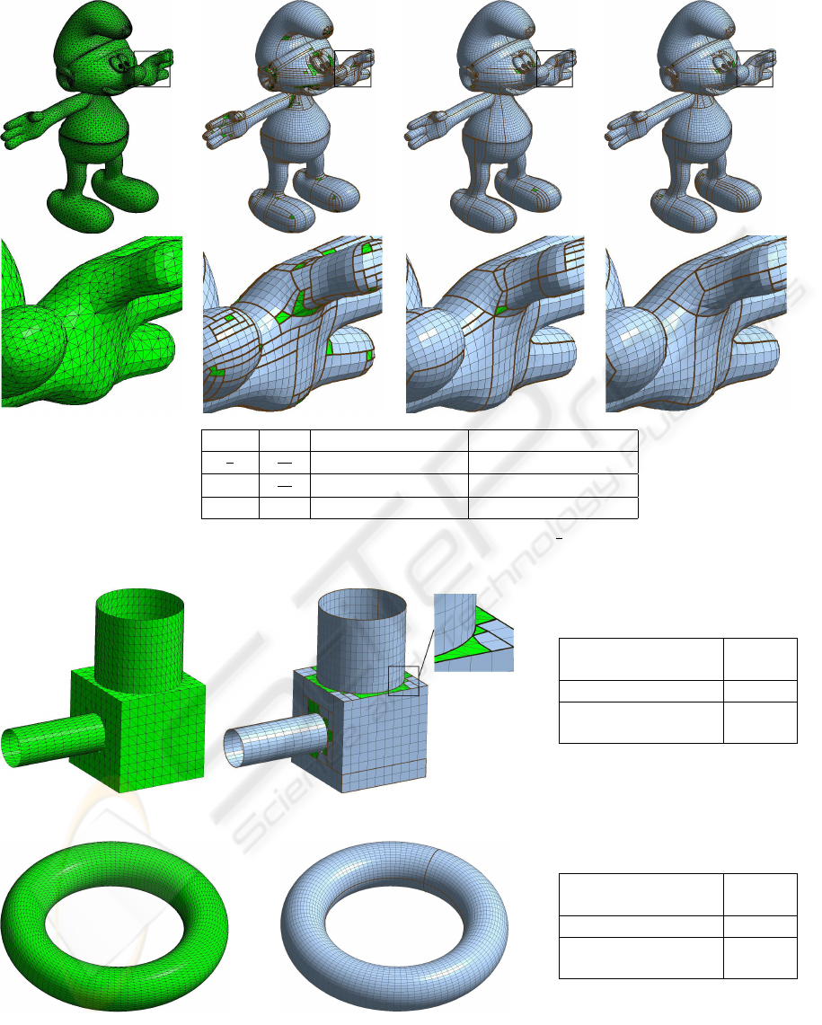
Q
max
φ
min
Number of patches Covering percentage
π
2
5π
6
931 91.39%
π
5π
6
519 98.52%
2π 2π 502 98.56%
Figure 14: The mesh Smurf with a zoom mesh and the obtained results with Q
max
=
π
2
, π and 2π (left to right). The number
of patches decreases and their sizes increase. So the covering with the decomposition is better on this example.
Triangles in the
mesh
2,608
Extracted patches 21
Covering percent-
age
95.47%
Figure 15: Original mesh and result for: CubeCylinders.
Triangles in the
mesh
9,384
Extracted patches 1
Covering percent-
age
100%
Figure 16: Original mesh and result for: Torus.
create quads satisfying a quality criterion. Quads are
then aggregated into quadrangulated areas which are
finally decomposed into patches.
This decomposition into quadrangulated patches
can be used in many applications such as the creation
of parametric surfaces, subdivision, or the numerical
GRAPP 2010 - International Conference on Computer Graphics Theory and Applications
102

calculation.
Comparison with other existing methods, quad-
rangulation and decomposition ones, should be made.
The proposed method can be improved in each
of its three steps. First, defining other quality coef-
ficients could improve the extraction of quadrangu-
lated areas. According to computed parameters on the
complete mesh, averages of angles computed for all
the vertices seems to be a good way. The constraints
can also be adjusted according to its local “shape”, by
relaxing for example the constraints of the dihedral
angle in the most curved part of the object.
Other propagation algorithm for the creation of
quadrangulated areas, can be proposed or the research
of rectilinear polygons can be optimized. The objec-
tive of these two modifications would be to decrease
the number of isolated triangles.
Another possible improvement would be to avoid
the step of extracting rectilinear polygons, and to de-
compose directly quadrangulated areas into patches.
This would enable to optimize globally the process
and to decrease the number of patches constituted by
a single quad which do not belong to the final decom-
position.
A last step of patch merging could be added and
it would enable to group two patches in only one, in-
tegrating if it is necessary adjacent isolated quads. If
it does not improve the percentage of covering, it will
decrease the number of patches of the decomposition.
Finally, some feature lines could be used, as
the “ridge lines” to define potential boundaries for
patches. The decomposition would be then optimized
using this knowledge as it is done in several remesh-
ing algorithms.
ACKNOWLEDGEMENTS
The authors want to thank the C4W company and the
Association Nationale de la Recherche et de la Tech-
nologie (ANRT) for their financial support.
REFERENCES
Alliez, P., Cohen-Steiner, D., Devillers, O., Lvy, B., and
Desbrun, M. (2003). Anisotropic polygonal remesh-
ing. ACM Transactions on Graphics, SIGGRAPH
2003 Conference Proceedings, 22(3):485–493.
Alliez, P., Ucelli, G., Gotsman, C., and Attene, M.
(2007). Recent advances in remeshing of surfaces.
In Shape Analysis and Structuring, pages 53–82.
Springer Berlin Heidelberg.
Arden, G. (2001). Approximation Properties of Subdivision
Surfaces. PhD thesis, University of Washington.
Bommes, D., Vossemer, T., and Kobbelt, L. (2009a). Quad-
rangular parametrization for reverse engineering. Lec-
ture Notes in Computer Science (to appear).
Bommes, D., Zimmer, H., and Kobbelt, L. (2009b).
Mixed-integer quadrangulation. ACM Trans. Graph.,
28(3):1–10.
Borouchaki, H., Frey, P. J., and George, P. L. (1997). Mail-
lage de surfaces param
´
etriques. Partie III: El
´
ements
quadrangulaires. 325(1):551–556.
Catmull, E. and Clark, J. (1978). Recursively generated
B-spline surfaces on arbitrary topological meshes.
Computer-Aided Design, 10(6):350–355.
Dong, S., Bremer, P.-T., Garland, M., Pascucci, V., and
Hart, J. C. (2006). Spectral surface quadrangulation.
ACM Trans. Graph., 25(3):1057–1066.
Dong, S., Kircher, S., and Garland, M. (2005). Har-
monic functions for quadrilateral remeshing of arbi-
trary manifolds. Computer Aided Geometry Design,
Special Issue on Geometry Processing, 22(5):392–
423.
Eppstein, D., Goodrich, M. T., Kim, E., and Tamstorf, R.
(2008). Motorcycle graphs : Canonical mesh parti-
tioning. Comput. Graph. Forum, 27(5):1477–1486.
Frey, P. J. and George, P. L. (1999). Maillage : Applications
aux
´
el
´
ements finis. Hermes Science.
Hormann, K. and Greiner, G. (2000). Quadrilateral remesh-
ing. In Girod, B., Greiner, G., Niemann, H., and Sei-
del, H.-P., editors, Proceedings of Vision, Modeling,
and Visualization 2000, pages 153–162, Saarbr
¨
ucken,
Germany.
Huang, J., Zhang, M., Ma, J., Liu, X., Kobbelt, L., and Bao,
H. (2008). Spectral quadrangulation with orientation
and alignment control. ACM Trans. Graph., 27(5):1–
9.
Krishnamurthy, V. and Levoy, M. (1996). Fitting smooth
surfaces to dense polygon meshes. In Proceedings of
SIGGRAPH 96, pages 313–324.
Lai, Y.-K., Kobbelt, L., and Hu, S.-M. (2009). Feature
aligned quad dominant remeshing using iterative lo-
cal updates. Computer-Aided Design (to appear).
Miyazaki, R. and Harada, K. (2009). Transformation of
a closed 3D triangular mesh to a quadrilateral mesh
based on feature edges. IJCSNS International Journal
of Computer Science and Network Security, 9(5).
Owen, S. J., Staten, M. L., Canann, S. A., and Saigal, S.
(1998). Advancing front quadrilateral meshing using
triangle transformations. 7th International Meshing
Roundtable, pages 409–428.
Soltan, V. and Gorpinevich, A. (1993). Minimum dissec-
tion of a rectilinear polygon with arbitrary holes into
rectangles. Discrete and Computational Geometry,
9(1):57–59.
Tarini, M., Pietroni, N., Cignoni, P., Panozzo, D., and
Puppo, E. (2010). Practical quad mesh simplification.
Computer Graphics Forum, 29(2):To appear.
DECOMPOSITION OF A 3D TRIANGULAR MESH INTO QUADRANGULATED PATCHES
103
