
TOPMESH
A Tool for Extracting Topological
Information from Non-manifold Objects
Leila De Floriani, Laura Papaleo
Department of Information and Computer Science, University of Genova, Italy
Annie Hui
Department of Computer Science, University of Maryland, U.S.A.
Keywords: Shape Modelling, Shape Understanding, Structural Representation, Non-manifold Geometry.
Abstract: We present TopMesh, a tool for extracting topological information from non-manifold three-dimensional
objects with parts of non-uniform dimensions. The boundary of such objects is discretized as a mesh of
triangles and of dangling edges, representing one-dimensional parts of the object. The geometrical and
topological information extracted include the number of elements in the mesh, the number of non-manifold
singularities and the Betti numbers, which characterize the topology of an object independently of the
discretization of its boundary. TopMesh also computes a decomposition of the mesh into connected parts of
uniform dimension, into edge-connected components formed by triangles, and into oriented edge-connected
sub-meshes. We describe the functionalities of TopMesh and the algorithms implementing them.
1 INTRODUCTION
A 3D object is most commonly described through a
discretization of its boundary into a mesh consisting
of triangles and of dangling edges, which do not
bound any triangle. We call these meshes, known in
algebraic topology as simplicial meshes, triangle-
segment meshes. They are common in a variety of
application domains, including computer graphics,
solid modeling, finite element analysis, virtual
reality, animation and scientific visualization.
Triangle-segment meshes are specifically well suited
for describing complex non-manifold objects.
Informally, a manifold 3D object is an object in
which the neighbourhood of every point on its
boundary is topologically equivalent to a disk, or to
a half disk. If the boundary of the object is
triangulated, the manifold condition translates into
the fact that the set of triangles incident at any vertex
form a disk, or a half disk. Objects, that do not fulfil
this property at one or more points, are called non-
manifold, and if they also contain parts of different
dimensionalities, are called non-regular.
While there exist tools to extract geometric and
topological information from manifold shapes, much
less work exists on extracting such information from
non-manifold ones. TopMesh is a tool for the
extraction of topological information about a 3D
object based on an analysis of its combinatorial
representation. The basic idea, here, is translating
topological properties in the continuum case into
combinatorial properties of the discrete
representation of the object as a triangle-segment
mesh.
Triangle-segment meshes arise from the
idealization of manifold triangular meshes obtained
by the discretization of CAD models for finite
element analysis.
Features of TopMesh are related to the extraction
of non-manifold singularities, parts of the object
boundary with different degrees of connectivity, and
with different dimensions. Moreover, TopMesh
allows computing a topological signature for a 3D
object, given by the so-called the Betti numbers.
Betti numbers provide a characterization of the
topology of the object independent of the
discretization of its boundary, which is particularly
useful in shape analysis and retrieval. Betti numbers
are topological quantities corresponding to the
21
De Floriani L., Papaleo L. and Hui A. (2010).
TOPMESH - A Tool for Extracting Topological Information from Non-manifold Objects.
In Proceedings of the International Conference on Computer Graphics Theory and Applications, pages 21-29
DOI: 10.5220/0002819400210029
Copyright
c
SciTePress
connectivity of the object and to number of through-
holes or handles, and of hollow cavities in the
object.
TopMesh is implemented based on a library for
encoding and manipulating triangle-segment
meshes, the Triangle-Segment (TS) Library, freely
available in (AIM@SHAPE, 2007).
The reminder of this paper is organized as
follows. In Section 2, we provide the mathematical
background with definitions and intuitive
descriptions. In Section 3, we discuss related work,
while in Section 4 we briefly describe the TS data
structure. Section 5 is devoted to the description of
the main functionalities of TopMesh, and in Section
6 we focus on the extraction of the Betti numbers. In
Section 7, we presents results obtained on specific
non-manifold datasets. Finally, in Section 8 we draw
some concluding remarks.
2 BACKGROUND NOTIONS
In this Section, we introduce fundamental definitions
as basis for our work.
We call a triangle-segment mesh any two-
dimensional mesh discretizing the boundary of a
non-manifold and non-regular three-dimensional
object. Thus, a triangle-segment mesh is a two-
dimensional simplicial complex embedded in the
three dimensional Euclidean space (Agoston, 2005).
The basic entities in a triangle-segment mesh are
triangles, edges that do not bound any triangles, that
we call wire-edges, and vertices. The collection of
all the vertices and edges of a triangle-segment mesh
form the 1- skeleton of the mesh.
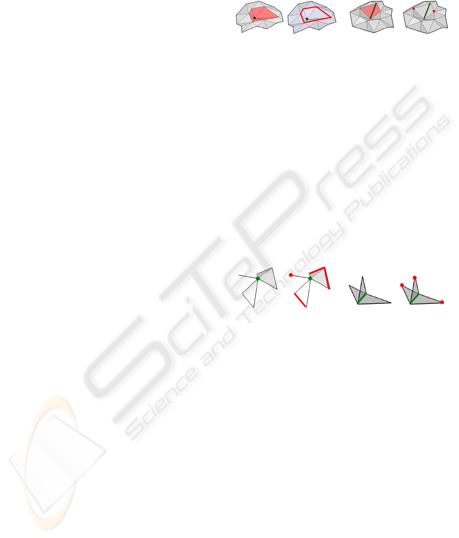
The star of a vertex v is defined as the set of
triangles and edges that are incident at v. The link of
v is defined as the set of edges and vertices in the
star of v which are not incident in v (Agoston, 2005).
Figure 1(a) and Figure 1 (b) show, respectively, the
star and the link of a vertex. In a similar way, the
star of an edge e is the set of triangles that are
incident at e. The link of e is the set of vertices of
the triangles in the star of e which are not extreme
vertices e.
Figure 1 (c) and Figure 1 (d) show,
respectively, the star and the link of an edge.
A triangle-segment is connected when its 1-
skeleton is a connected graph. A triangle-segment is
edge-connected when, for every pair of triangles t
1
and t
2
of , there is a path in composed of an
alternating sequence of triangles and edges such that
any edge in the path is shared by two triangles
preceding and following it. A triangle-segment mesh
without wire-edges is just a triangle mesh. If it
contains at least one edge that is bounding exactly
one triangle, it is called a triangle mesh with
boundary.
v
v
e
e
(a) (b) (c) (d)
Figure 1: The star and the link of a vertex and an edge: (a)
the star of vertex v; (b) the link of vertex v ; (c) the star of
edge e; (d) the link of edge e.
A vertex v in a triangle-segment mesh is a
manifold vertex if its link consists of one or two
vertices, i.e., v belongs only to one or two wire-
edges, or if the link of v consists of a closed or open
chains of edges, i.e., v is shared by a fan of triangles
forming a full disk (as in the example
Figure 1(a)) or
a half disk (in this latter case v is a boundary vertex).
An edge is a manifold edge if its link consists of one
or two vertices (as in the example
Figure 1(c)).
A vertex, or an edge which does not satisfy the
above properties is called a non-manifold vertex or
non-manifold edge, respectively. Examples of non-
manifold vertices and edges are shown in
Figure 2, as
their relative links.
e
e
v
v
(a) (b) (c) (d)
Figure 2: (a) The star of non-manifold vertex v consists of
three components, one of which is a wire-edge and two of
which consist of triangles; (b) The link of v for the
example in (a); (c) The star of non-manifold edge e
consists of three triangles; (d) The link of e for the
example in (c) consists of three vertices.
The fundamental characterization of a three-
dimensional object is given by its Betti numbers β
0
,
β
1
and β
2
(Agoston, 2005). Specifically, β
0
is the
number of connected components, β
1
is the number
of 1-cycles, and β
2
is the number of 2-cycles.
Intuitively, the 1-cycles define the independent
tunnels, or handles, while the 2-cycles are parts of
the object which enclose empty space (voids). A 2-
cycle C in a triangle-segment mesh can be viewed
as an edge-connected component of without
boundary, such that the three-dimensional region
enclosed by C is connected, that is, every two points
in the region can be joined by a curve which does
not intersect any simplex of .
Figure 3(a) shows an
example of an object with one 1-cycle and one 2-
cycle (the cube), while
Figure 3(b) shows an example
GRAPP 2010 - International Conference on Computer Graphics Theory and Applications
22
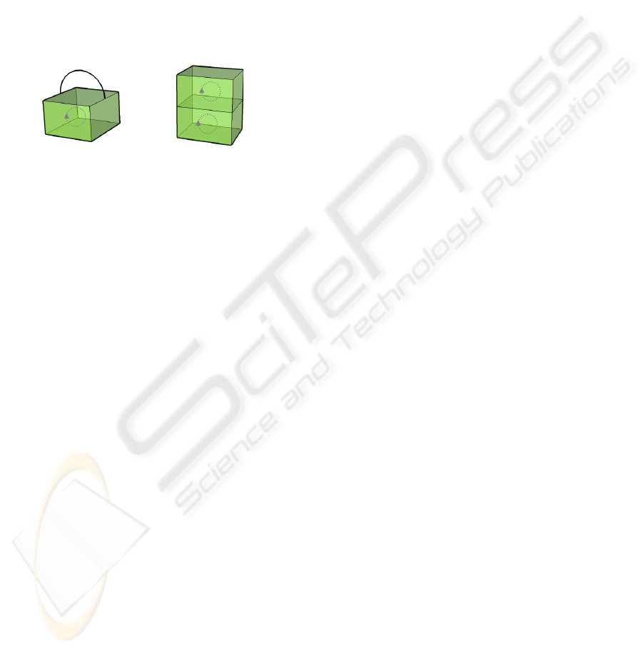
of an object with two 2-cycles (the two cubes
sharing a face). The Betti numbers are topological
invariants and are independent of the way the object
boundary is discretized.
On the other hand, the quantity β
0
-β
1
+β
2
, which
is called the Euler characteristic of the object, is
related by Euler Poincare’s formula
n – e + f = β
0
– β
1
+ β
2
(1)
where n is the number of vertices, e the number
of edges, and f the number of triangles in the
triangle-segment mesh discretizing the object
boundary.
(a) (b)
Figure 3: (a) An object formed by one 2-cycle and one 1-
cycle; for this object: β
0
=β
1
=β
2
=1); (b) an object with two
2-cycles, each of which is the interior of a parallelepiped:
for this object: β
0
=1 β
1
=0 and β
2
=2).
3 RELATED WORK
In this Section, we review some related work on
topological segmentation of non-manifold shapes
and on the computation of topological invariants.
In the literature, several techniques have been
proposed for segmenting the boundary of a 3D
manifold shape, see (Shamir, 2006) for a survey.
Such techniques try to decompose an object into
meaningful components, i.e., components which can
be perceptually distinguished from the remaining
part of the object. Some methods have been
developed in CAD/CAM for extracting the so-called
form features, like protrusions, depressions or
through-holes, which produce a boundary-based
decomposition of a 3D object guided by geometric,
topological and semantic criteria, see (Shah, 1991)
for a survey.
Much less work has been done on decomposition
of non-manifold shapes. A common approach to
represent a non-manifold shape consists of
decomposing it into manifold components. Some
techniques have been proposed in the literature for
decomposing the boundary of regular non-manifold
3D shapes (called r-sets), i.e., for non-manifold
shapes which do not contain dangling faces or edges,
which are described by their boundary. In
(Falcidieno and Ratto, 1992), the idea of cutting a
two-dimensional non-manifold shape into manifold
pieces is exploited to develop compression
algorithms. In (Delfinado and Edelsbrunner, 1995;
Desaulnier and Stewart, 1992), a representation
scheme based on the decomposition of an r-set into
its manifold parts. In (Rossignac and Cardoze,
1999), a decomposition algorithm for non-manifold
shapes is presented which minimizes the number of
duplications introduced by the decomposition
process. In (Pesco et al., 2004) the authors propose a
decomposition of a 2D cell complex based on a
combinatorial stratification of the complex, inspired
by Whitney stratification and a set of topological
operators for manipulating it.
In (Delfinado and Edelsbrunner, 1995) an
incremental algorithm is proposed for computing the
ranks of the homology groups (Betti numbers) for
simplicial 3-complexes embeddable in the three-
dimensional Euclidean space R
3
.
The basic idea is to build a complex by adding
one simplex at a time, and at each step the Betti
numbers are updated to reflect the changes in the
homology groups.
The authors discuss implementations of the
algorithm that run in time O(n(n)) and O(n), where
n is the number of simplexes in the complex.
(Dey and Guha, 1998) present an approach to
compute the generators of the homology groups for
compacted triangulated 3-manifolds in R
3
. Then,
they show that this approach can be applied to
arbitrary simplicial complexes in R
3
, after thickening
the complex to produce a 3-manifold homotopic to
it. Finally, a classical algebraic approach to the
computation of homology groups is discussed in
(Gueziec et al., 1998).
4 THE TS LIBRARY
We recall that a triangle-segment mesh is encoded as
a Triangle-Segment (TS) data structure. The TS data
structure is the non-manifold extension of the
indexed data structure with adjacencies, which is the
most common representation for triangle meshes. It
is compact and scalable and it supports efficient
navigation algorithms (De Floriani et al., 2004). The
TS data structure encodes the triangles, wire-edges
and vertices of the mesh. The wire-edges and the
triangles are represented by encoding relations wire-
edge-vertex and triangle-vertex, respectively.
For each wire edge e, wire-edge-vertex relation
associates the two extreme vertices with edge e;
For each triangle t, the triangle-vertex relation
associates triangle t with its three vertices (see
TOPMESH - A Tool for Extracting Topological Information from Non-manifold Objects
23
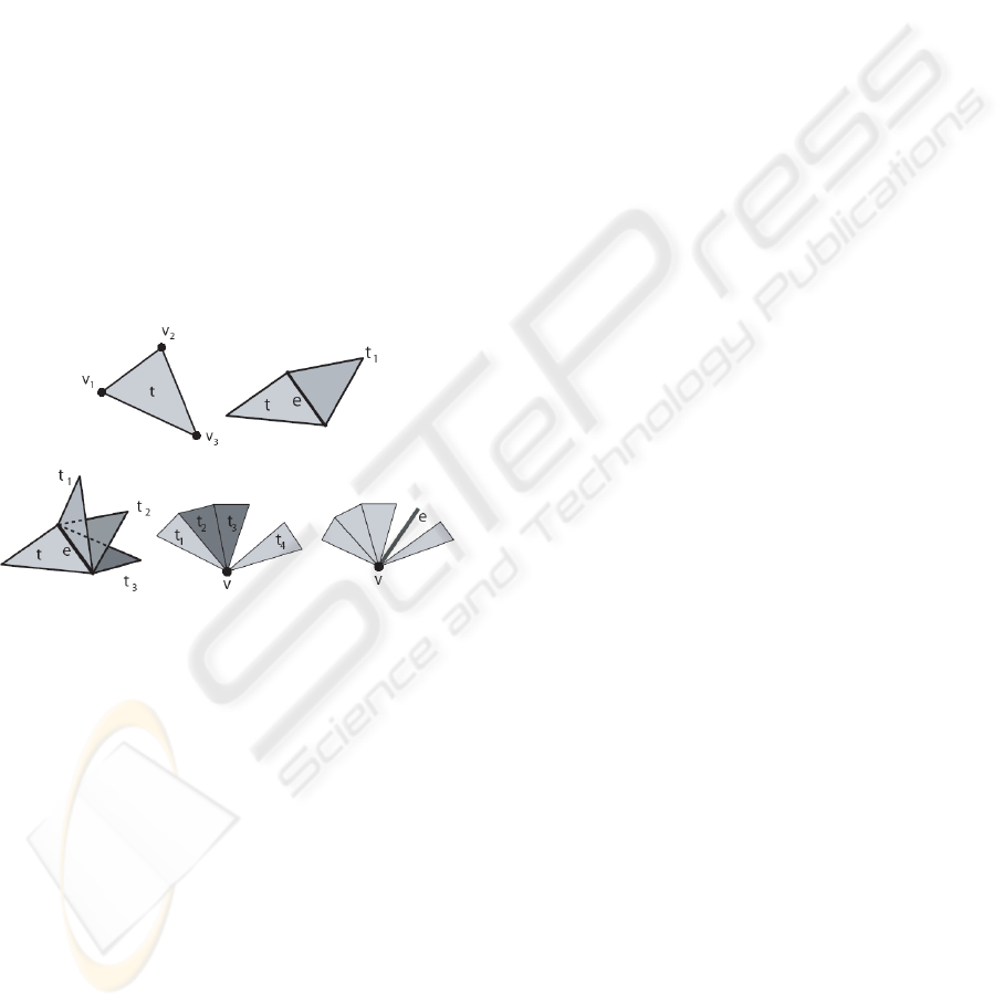
Figure 4 (a)).
The relation among a triangle t and its edge-
adjacent triangles may involve an arbitrary number
of triangles along each edge of t, since an edge can
be non-manifold.
For compactness, the TS data structure stores, for
each edge e of a triangle t, the two triangles that are
immediately preceding and succeeding t around e,
when the triangles incident at e are sorted in counter-
clockwise order around e, as shown in
Figure 4 (b)).
We call such relation the partial triangle-triangle-at-
edge relation The counter-clockwise order of an
edge e is defined by considering one of the two
possible orientations of e and by applying the right-
hand rule with the thumb pointing consistently with
vu, if e = (v, u) and the orientation vu is chosen
for e. If edge e is an interior manifold edge, the
predecessor and the successor are identical and
consist of the only other triangle t′ which share e
with t (see
Figure 4 (c)). When there is no triangle
adjacent to t along e, the predecessor and the
successor of t are both t.
(a) (b)
(c) (d) (e)
Figure 4: Topological information encoded in the TS data
structure for a triangle t (a), for an edge e (b) (c) and for a
vertex v (d) (e).
To simplify the task of navigating the mesh
around a vertex, the TS data structure encodes for
each vertex v (see
Figure 4 (d-e))
(i) the vertex-triangle relation, which
associates with v one triangle for each edge-
connected component in the star of v;
(ii) the vertex-wire-edge relation which
associates with v all the wire edges incident at
vertex v.
All the topological relations among the entities in
the TS data structure (vertices, wire-edges and
triangles) can be extracted in time linear in the
number of entities involved in the relations (De
Floriani et al., 2004). The source code of the TS
data structure library is freely available in an online
tool repository (AIM@SHAPE, 2007).
5 BASIC FUNCTIONALITIES
We present here the basic functionalities of
TopMesh, and describe the algorithms for extracting
the topological information on which it is based.
TopMesh extracts the following topological
information from an object whose boundary is
discretized as a triangle-segment mesh:
non-manifold singularities: non-manifold
vertices, non-manifold edges and wire-edges;
components with various degrees of
connectivity, namely connected components,
wire-webs, which are maximal connected
components formed by the wire-edges, and edge-
connected components, which describe the parts
of the object which do not contain non-manifold
vertices;
In the following subsections we show how,
relying on the TS data structure, TopMesh extracts
the information listed above. In Section 6, we
describe the computation of the Betti numbers, and
specifically, we propose an algorithm for computing
the number of 2-cycles.
5.1 Extracting Non-manifold
Singularities
We consider a triangle-segment mesh encoded in a
TS data structure. Wire-edges are explicitly encoded
in the TS and thus their retrieval and counting is
trivial.
A non-manifold vertex v is identified by
counting the number of connected components in the
link of v. This is performed by considering the
vertex-triangle and vertex-wire-edge relations at v
encoded in the TS data structure: v is manifold if
only one of the two relations is not empty, and
(i) if the vertex-triangle relation is not empty,
and it consists only one triangle; or
(ii) if the vertex-wire-edge relation is not
empty, and it consists of either one or two wire-
edges.
Otherwise vertex v is non-manifold.
A non-manifold edge e is detected by
considering a triangle t incident at e and checking
whether t has a predecessor and successor in the
triangle-triangle-at-edge relation of t at e in the TS
data structure, which are different. Otherwise edge e
is manifold.
5.2 Extracting Connected Components
and Wire-webs
Connected components of a triangle-segment mesh
GRAPP 2010 - International Conference on Computer Graphics Theory and Applications
24

are identified by applying a connected component
labeling algorithm to . This is performed as a
breadth-first traversal in the TS data structure. The
traversal of each connected component starts at an
arbitrary unvisited vertex v of , and visits all
triangles in the vertex-triangle relation encoded in
the TS data structure, and all the wire-edges in the
vertex-wire-edge relation at v. Then, all the vertices
which are bounding such triangles and wire-edges
are considered, and if they are not visited, they are
inserted in a queue Q.
The traversal continues by extracting the first
vertex in the queue and considering it as current
vertex. A connected component is completely
traversed when the queue is empty. By repeating this
traversal process until no unvisited vertex is left, all
the connected components are retrieved.
Wire-webs are connected components formed
only of wire-edges. To detect and count such
components, a traversal similar to the one described
above is performed, but, at each vertex v, only the
incident wire-edges are considered.
The edge-connected components are computed
by considering the sub-mesh ′ obtained from the
original one by eliminating all the wire-webs. The
edge-connected components correspond to
connected components of the dual graph
representing ′. In the dual graph, the nodes
correspond to the triangles of ′ and the arcs to the
edges shared by two or more triangles.
Edge-connected components are extracted from
the TS data structure starting from an arbitrary
triangle t of ′. For each edge e of t, all the triangles
incident at e are extracted, marked as visited and
inserted in a queue Q. Then, the first triangle in Q is
extracted and the traversal is repeated from such
triangle.
An edge-connected component is completely
traversed when Q is empty. By repeating this
traversal process until no unvisited triangle is left, all
the edge-connected components are found.
It can be easily seen that all the above algorithms
have a time complexity which is linear in the size of
the mesh.
6 COMPUTING BETTI
NUMBERS
In this Section, we show how to compute a
topological signature of a 3D object based on its
Betti numbers β
0
, β
1
and β
2
. Recall that β
0
is the
number of connected components, β
1
is the number
of 1-cycles, and β
2
is the number of 2-cycles.
Given a 3D object represented as a triangle-
segment mesh encoded with the TS data structure, β
0
can be computed as the total number of the
connected components, β
2
needs to be computed by
extracting oriented sub-meshes of the edge-
connected components which enclose voids. Finally,
β
1
is obtained from Euler-Poincare’s formula by
computing the number of vertices, edges and
triangles in the mesh. Thus, the main step, here, is to
compute β
2
.
In the following subsections, we first provide
basic definitions and successively we present the
algorithm for computing the number of 2-cycles.
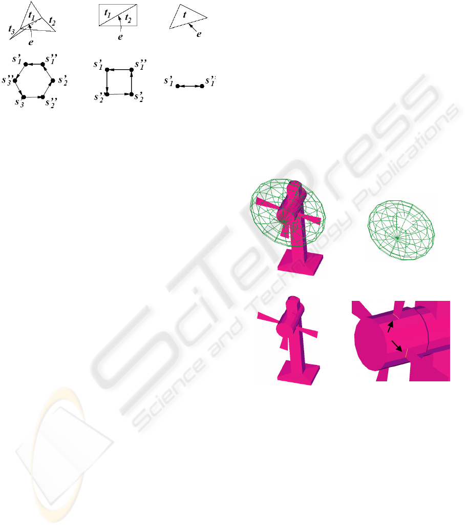
6.1 Oriented and Folded Surfaces
The algorithm for computing the Betti number β
2
of
a triangle-segment mesh is based on the concepts
of triangle sides, oriented surfaces and folded
surfaces.
A triangle t has two triangle sides (with opposite
normals) defined by the two possible orderings of its
vertices. Each triangle side induces an orientation on
each of its edges. In
Figure 5 (a) an example is shown
where the edge connecting vertices a and b has
orientation ab on one triangle side, and ba on
the opposite side. Two triangle sides are adjacent at
their common edge e if one is reachable from the
other by crossing e.
For each edge-connected component in the
mesh, we can extract connected collections of
triangle sides for the triangles in , that we call
oriented surfaces. An oriented surface is a maximal
edge-connected set of triangles sides, such that, for
each pair of triangle sides s′, s′′ in the set sharing an
edge e, s′ is the successor of s′′ according to one
orientation of e, and s′′ is the successor of s′
according to the opposite orientation of e. In other
words, the two triangle sides that belong to two
different triangles, which share a common edge,
induce an opposite orientation on their common
edge (see
Figure 5 (b)).
To clarify the definition of oriented surface, let
us consider the example shown in
Figure 5 (c).
Imagine an ant walking on the upper side of triangle
t (that is T
1
).
It reaches the triangle side U
1
by crossing edge
(a, b). It reaches the opposite side of t (T
2
) by
crossing edge (a, c), because (a, c) is a boundary
edge. An oriented surface is basically the surface
formed by all the triangle sides that are reachable by
a walking ant.
TOPMESH - A Tool for Extracting Topological Information from Non-manifold Objects
25
An oriented surface may enclose a void. An
oriented surface S with boundary, such that for each
triangle side s that belongs to S the other side s′′ of
the same triangle also belongs to S, cannot enclose
any void.
a
b
c
a
b
c
a
b
c
c
a
b
(a) (b)
a
b
c
T
U
V
V
2
V
1
U
1
U
2
T
2
T
1
(c)
Figure 5: (a) Example of the two possible triangle sides for
a triangle t (b) example of adjacency between two triangle
sides. (c) example for an oriented surface. An oriented
surface is basically the surface formed by all the triangle
sides that are reachable (via adjacency) by a walking ant.
We call such oriented surface a folded surface. If
an edge-connected component consists of only one
oriented surface, it must be a folded surface. may
consist of two surfaces, as it is always the case if it
contains only manifold edges.
For instance, if is a triangulated sphere, it
consists of two oriented surfaces, each of which
corresponding to an orientation of the surface of the
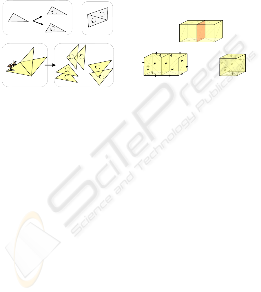
sphere. If consists of two triangulated cubes
sharing a face, then there are three oriented surfaces
associated with it, namely the two cubes with
normals pointing towards the inside and the oriented
surface consisting of the union of the two cubes with
the normals pointing towards the external empty
space (see
Figure 6).
It can be easily seen that, if we consider an edge-
connected component of the original mesh, there
exists exactly one oriented surface in the set of
oriented surfaces associated with it, that we denote
S
out
, such that the normals to the triangle sides
forming it point towards the outside space.
S
out
defines a cycle of triangles which can be
expressed as the linear combination of the other
oriented surfaces associated with . Thus, unlike the
other oriented surfaces in , S
out
does not define a 2-
cycle, since it contains the remaining oriented
surfaces.
Note that, if consists of one folded surface, this
latter does not define a 2-cycle as well. Since there is
exactly one oriented surface for each edge-
connected component which does not define a 2-
cycle, we have that the number of 2-cycles in the
model is equal to the total number of oriented
surface minus the number of 1-connected
components.
(a)
(
b
)
(
c
)
Figure 6: (a) Two triangulated cubes sharing a face; (b) the
oriented surface with normals pointing towards the
external space; (c) one of the two oriented surfaces with
normals pointing towards the enclosed void.
6.2 Algorithm
The oriented surfaces in an edge-connected
component can be computed by defining a
di-graph G
A
on the collection of the triangle sides of
, that we call the oriented adjacency di-graph of .
In G
A
, the nodes are the triangle sides, while there is
a directed arc from a node s′ to a node s′′ if and only
if the two sides s′ and s′′ share an edge e, and side s′′
is the successor of s′ at e. Note that graph G
A
may
contain parallel arcs oriented in the opposite
direction since two sides of the same triangle can be
the successors of each other at a boundary edge.
Figure 7 (a)-(c) show three examples of oriented
adjacency di-graphs for (a) three triangles sharing a
non-manifold edge, (b) two triangles sharing a
manifold edge and (c) a triangle with a boundary
edge.
Each strongly connected sub-graph of the
oriented adjacency di-graph G
A
defines an oriented
surface. A strongly-connected component of graph
G
A
is any maximal subgraph H
A
of G
A
such that any
node s′′ in H
A
can be reached from any other node s′
of H
A
through a directed path. If we consider all the
triangle sides corresponding to the nodes in the
strongly-connected component H
A
, they form a
maximal edge-connected set of triangle sides such
that any pair of triangle sides s′ and s′′ are connected
through a path on the complex formed by edge-
adjacent triangles which are consistently oriented.
Thus, they form an oriented surface.
GRAPP 2010 - International Conference on Computer Graphics Theory and Applications
26
We do not actually build the oriented adjacency
di-graph, but we simulate it on the TS data structure.
To this aim, we label each triangle t in the TS data
structure with two bit flags.
(a) (b) (c)
Figure 7: (a) Three triangles sharing a non-manifold edge
e and the corresponding di-graph; (b) Two triangles
sharing a manifold edge e and the di-graph at e; (c) A
triangle with a boundary edge e and the di-graph at e.
The first bit flag corresponds to the side of t
defined by the order of the vertices of t as the they
are encoded in the triangle-vertex relation, the
second one to the opposite side of t. A bit flag is
equal to 0 if the corresponding side has not been
visited, it is equal to 1 otherwise. The traversal of
the directed arcs emanating from a node s′ in the
oriented adjacency di-graph corresponds to finding
the successors of triangle side s′ in the TS data
structure along its three edges which have an
orientation consistent with s′. Let us consider an
edge e of s′ and let s′′ be the successor of s′ in the
oriented surface (and, thus, (s′, s′′) is an arc in G
A
).
We consider the triangle t corresponding to s′. Let
the orientation of e = (v, u) in the TS data structure
be vu. We consider relation triangle-triangle-at-
edge of t at edge e, which returns the pair (f
1
, f
2
),
where f
1
is the successor of t in counter-clockwise
and f
2
is the successor of t in clock-wise order,
according to the orientation of e.
Now, s′′ will be a side of f
1
chosen in such a way
that s′′ induces an opposite orientation on edge e
with respect to the one induced by s′. Note that, if e
is a boundary edge, than f
1
=f
2
=t and s′′ is the other
side of t with respect to s′.
Also, since the algorithm performs a visit on the
di-graph G
A
and the number of nodes in G
A
is
proportional to the number of triangles and edges in
the input mesh, the algorithm complexity is linear in
the size of the mesh.
7 DISCUSSION
TopMesh is a command line tool written in C++. It
has been tested on several data sets on a dual-core
2.66GHz CPU, 1GB RAM WinXP platform.
In this Section, we show two examples of results
of the application of TopMesh on non-manifold
objects.
Figure 8(a) shows a table fan. It has a wire-web
component (see Figure 8 (b)) and an edge-connected
component (see
Figure 8 (c)). Figure 8 (d) shows the
table fan connectivity at non-manifold edges. The
geometrical and topological data extracted by
TopMesh for this model are summarized in Table 1.
TopMesh also extracts the sub-meshes of the input
meshes forming connected components, wire-webs
and edge-connected components and also the
oriented surfaces generated in the process of
computing β
2
.
(a) (b)
(c) (d)
Figure 8: A non-manifold model representing a table fan
(a). This model has a single wire-web in (b) and a single
edge-connected component in (c). In (d) a zoom showing
the non-manifold edges.
Figure 9 (a) shows a non-manifold model
representing a chandelier. It has a wire-web
component (see Figure 9 (b)) and 10 different edge-
connected components (two of them are shown in
Figure 9 (c)-(d)). Figure 9 (e) shows the chandelier
connectivity at a non-manifold edge., The
topological data extracted by TopMesh are
summarized in Table 2.
TOPMESH - A Tool for Extracting Topological Information from Non-manifold Objects
27
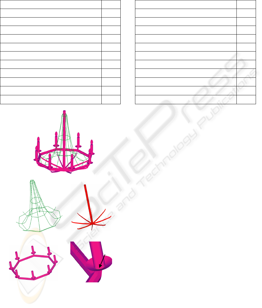
Table 1: Topological information extracted by TopMesh
from a non-manifold triangle-segment mesh representing a
table fan.
Property Value
Number of triangles 380
Number of Vertices 325
Number of edges 846
Number of wire-edges 272
Number of non-manifold vertices 145
Number of non-manifold edges 4
Number of wire-webs 1
Number of connected components (
0
)
1
Number of edge-connected components 2
Number of 1-cycles (
1
)
143
Number of 2-cycles (
2
)
1
(a)
(b) (c)
(d) (e)
Figure 9: A non-manifold model representing a chandelier,
which has a one wire-web (b) and 10 different edge-
connected components - two of them in (c) and (d). In (e)
chandelier connectivity at a non-manifold edge.
Table 2: Topological information extracted by TopMesh
from a non-manifold triangle-segment mesh representing a
chandelier.
Property Value
Number of triangles 18304
Number of Vertices 9242
Number of edges 27600
Number of wire-edges 136
Number of non-manifold vertices 80
Number of non-manifold edges 264
Number of wire-webs 1
Number of connected components (
0
)
1
Number of edge-connected components 10
Number of 1-cycles (
1
)
65
Number of 2-cycles (
2
)
10
A web page presenting TopMesh and showing
additional results, has been prepared and it is
available at the following URL: http://ggg.disi.
unige.it/topmesh/. On the web page the reader can
eventually find additional material and images of the
results.
8 CONCLUDING REMARKS
We addressed the problem of extracting topological
characteristics from non-manifold 3D shapes
containing parts of different dimensions, and
discretized as simplicial complexes.
We presented TopMesh as a tool for the
extraction of topological information by analysing a
3D object represented as a triangle-segment mesh
encoded in the TS data structure. We showed how,
by using the relations of the TS, we are able to
extract topological information of the input mesh
and we provived an algorithm for computing the
topological 3D object signature via the Betti
numbers.
Actually, TopMesh is being integrated as a core-
module in a Semantic Web system (Papaleo et al.,
2007; De Floriani et al., 2007), for inspecting 3D
shapes and for structuring and annotating such
shapes according to ontology-driven metadata. This
system has been designed to support researchers in
reasoning on digital shapes and in improving their
knowledge about multimedia data available on the
web.
As a further activity we want to extend the tool
for performing a semantic-oriented decomposition of
GRAPP 2010 - International Conference on Computer Graphics Theory and Applications
28

a shape. This decomposition could be applied, for
example, for classifying form features in simplicial
shapes obtained as idealization of CAD models in
the product analysis phase. Also, the decomposition
can be the basis for a semantic-based annotation of
complex 3D objects. We plan, also, to extend
TopMesh in order to manage large non-manifold
meshes using spatial indexing techniques.
ACKNOWLEDGEMENTS
This work has been partially supported by the
MIUR-FIRB project SHALOM under contract
number RBIN04HWR8, by the National Science
Foundation under grant CCF-0541032, and by the
MIUR-PRIN project on Multi-resolution modeling
of scalar fields and digital shapes. The authors
would like to thank May Huang for the support in
the implementation
REFERENCES
Agoston M. (2005) Computer Graphics and Geometric
Modelling: implementation and algorithms. Springer.
Campagna S., Kobbelt L., and Seidel H.P. (1998)
“Directed edges a scalable representation for triangle
meshes”. Journal of Graphics Tools, 3(4):1–12.
De Floriani L. and Hui A. (2007) “Shape representations
based on simplicial and cell complexes”. In
Eurographics 2007, State-of-the-Art Report, pp.63–88.
De Floriani L., Hui A., Papaleo L., Huang M., Hendler J.
A. (2007) “A Semantic Web Environment for Digital
Shapes Understanding”. In Lecture Notes in Computer
Science, Semantic Multimedia, SAMT 2007, vol.4816
pp. 226–239. Springer.
De Floriani L., Magillo P., Puppo E. and Sobrero D.
(2004) “A multi-resolution topological represent-tation
for non-manifold meshes”. Computer-Aided Design
Journal, 36(2):141– 159, February.
Delfinado C. A. and Edelsbrunner H. (1995) “An
Incremental Algorithm For Betti Numbers Of
Simplicial Complexes on the 3-Sphere”. Computer
Aided Geometric Design, 12(7):771--784.
Desaulnier H. and Stewart N. (1992) “An Extension of
Manifold Boundary Representation to R-Sets”. ACM
Transactions on Graphics, 11(1):40-60.
Dey T. K., and Guha S. (1998) “Computing Homology
Groups of Simplicial Complexes in R
3
” Journal of the
ACM (JACM) 45(2):266-287.
Falcidieno B. and Ratto O. (1992) “Two-manifold cell
decomposition of R-sets”. In Proceedings Computer
Graphics Forum, vol.11, pp.391-404.
Gueziec A., Taubin G., Lazarus F., and Horn W. (1998)
“Converting Sets of Polygons to Manifold Surfaces by
Cutting and Stitching”. In Proceedings of the
International SIGGRAPH’98, pp.245-245 ACM Press.
Munkres J. R. (1984) Elements of Algebraic Topology.
Addison- Wesley, Redwood City.
AIM@SHAPE NoE EC Network of excellence n.506766
(2007) www.aimatshape.net (last accessed Oct. 2009)
Papaleo L., De Floriani L., and Hendler J., (2007)
“Bridging Semantic Web and Digital Shapes”, In
Proceedings of the International Eurographics
Conference - Short Paper, Prague, September.
Pesco S., Tavares G. and Lopes H. (2004) “A
Stratification Approach for Modeling Two-
Dimensional Cell Complexes”. Computers and
Graphics Journal, (28):235-247.
Rossignac J. and Cardoze D. (1999) “Matchmaker:
Manifold B-Reps for Non-manifold R-sets”. In
Proceedings 5th Symposium on Solid Modeling and
Applications, pp.31-41. ACM Press, June.
Shah J. J. (1991) “Assessment of Features Technology”.
Computer-Aided Design, 23(5):331-343.
Shamir A. (2006) “Segmentation and Shape Extraction of
3D Boundary Meshes”. In State-of-the-Art Report,
Eurographics, Vienna.
TOPMESH - A Tool for Extracting Topological Information from Non-manifold Objects
29
