
ACTIVE3D: SEMANTIC AND MULTIMEDIA MERGING FOR
FACILITY MANAGEMENT
Renaud Vanlande
Groupe Archimen, 2 rue Renée Char, BP 66606, 21066 Dijon Cedex, France
Christophe Cruz, Christophe Nicolle
LE2I, UMR CNRS 5158, Université de Bourgogne, BP 47870, 21078 Dijon Cedex, France
Keywords: Interoperability, 3D collaborative platform, IFC, BIM, Semantic Web.
Abstract: This paper presents a Semantic Web approach for facility management. This Web-based platform lets
geographically dispersed project participants—from facility managers and architects to electricians to
plumbers—directly use and exchange project documents in a centralized virtual environment using a simple
Web browser. A 3D visualization lets participants move around in the building being designed and obtain
information about the objects that compose it. This approach is based on a semantic model called CDMF
and IFC 2x3. CDMF improves data management during the lifecycle of a building. Based on graph
combinations and the contextual element SystemGraph, our proposition, addresses the problem of model
evolution, of data mapping, management, of temporal data and the problem of the data adaptation according
to the use and the user. Our framework, based on Building Information Modeling features, facilitates data
maintenance (data migration, model evolution) during the building lifecycle and reduces the volume of data.
1 INTRODUCTION
The building lifecycle management requires the
development of a specific environment solving at the
same time the problems of syntactic and semantic
heterogeneity (Keith, 2004), (Barret, 2003).
Moreover, the environment should also allow the
required extensibility and the flexibility in order to
guarantee the coherent evolution of the collaborative
processes developed in this field. The information in
an AEC project is generated during all the building
lifecycle. It is essential to structure the information
in a relevant way for a better management. The
activities in an AEC project generate a huge variety
of data and information. Consequently, the
management and the communication of these data
by various participants are complex. The process of
information sharing requires a framework in which
computer programs can exchange data automatically
regardless of the software and data location.
Moreover, in this field, the use of tools for 3D
visualization of the buildings is crucial. Towards this
goal the IAI proposed a standard called IFC (IFC,
2007) that specifies object representations for AEC
projects (IAI, 2007). Industry foundation classes
(IFCs) include object specifications, or classes, and
provide a structure for data sharing among
applications. From a collaborative point of view the
IFCs form the basis of a building description. This
basis is enriched during the building’s lifecycle with
elements related to facilities management: financial
data, maintenance rules, evacuation procedures and
so on. The quantity of information becomes
exponential and then a relevant organization of these
elements becomes very complex. Today, “Building
Information Modeling (BIM)” is promising to be the
facilitator of integration, interoperability and
collaboration in the future of building industry. The
term BIM has been recently pointed to demarcate
the next generation of Information Technologies
(IT) and Computer-Aided Design (CAD) for
buildings.
21
Vanlande R., Cruz C. and Nicolle C.
ACTIVE3D: SEMANTIC AND MULTIMEDIA MERGING FOR FACILITY MANAGEMENT.
DOI: 10.5220/0002792000210029
In Proceedings of the 6th International Conference on Web Information Systems and Technology (WEBIST 2010), page
ISBN: 978-989-674-025-2
Copyright
c
2010 by SCITEPRESS – Science and Technology Publications, Lda. All rights reserved

2 BUILDING INFORMATION
MODELING
BIM is the process of generating, storing, managing,
exchanging and sharing building information in an
interoperable and reusable way. A BIM system is a
tool that enables users to integrate and reuse the
information of a building and the domain knowledge
throughout the lifecycle of a building (Lee, 2006). A
BIM system is a central system that manages various
types of information, such as enterprise resource
planning, resource analysis packages, technical
reports, meeting reports, etc. However, the main
feature of a BIM is the 3D modeling system with
data management, data sharing and data exchange
during the lifecycle of the building. As a matter of
fact, a building is composed of geometrical elements
which are the basis of a building’s design.
Furthermore, parametric modeling provides
powerful mechanisms that can automate the
generation of the building information. Especially
those mechanisms, in conjunction with the behavior
of building object and an object-based system,
facilitate the maintenance and the validity of the
building’s designs. Several definitions of BIM can
be found in the specialized literature. The NBIMS
(NBIMS, 2007a) divides BIM categories in three
axes which are Product, Collaborative Process and
Facility. The Product is an intelligent digital
representation of the building. The Collaborative
Process covers business drivers, automated process
capabilities and open information standards used for
information sustainability and fidelity. The Facility
concerns the well understood information
exchanges, workflows, and procedures which are
used by the different teams as a repeatable,
verifiable and sustainable information-based
environment throughout the building’s lifecycle.
According to (NBIMS, 2007b) a BIM is a
computable representation of all the physical and
functional characteristics of a building and it is
related to the project information, which is intended
to be a repository of information for the building
owner/operator to use and maintain throughout the
lifecycle of the building. According to Autodesk
(Autodesk, 2002), BIMs have three main features:
They create and operate on digital databases for
collaboration. They manage change through those
databases so that a change to any part of the
database is coordinated in all other parts. They
capture and preserve information for reuse by adding
industry-specific applications.
By analyzing the BIM definition we index a set of
features common to BIM systems (Tolman, 1999) ,
(NIST, 2007), (Eastman, 2005), (Zamanian, 1999),
(Sable, 2005), (Cruz, 2006). (1) The main feature of
BIM is the ability to store, share and exchange data.
Many methods are used to realize those processes
like files or databases. Concerning data exchange,
BIMs are developed with the aim to keep open non-
proprietary data format exchange. (2) Data managed
in BIM processes concerns building geometries
which are most of the time 3D data. 3D data is more
helpful for designers for the visualization of
complex construction conditions than 2D while it
communicates at the same time design intentions.
AEC industry visualizes the design using
stereoscopic projection tools to create an immersive
experience (Dace, 2007). Spatial relationships
between building elements are managed in a
hierarchical manner. (3) BIMS are data rich and
comprehensive as they cover all physical and
functional characteristics of a building. BIMs are
also rich semantically as they store a high amount of
semantic information about building elements.
Moreover, the data model is fully object oriented to
facilitate data management and process definition.
(4) Some of the BIMs are extensible to cover
unimplemented information domains. For instance,
the development of IFC 2.X went through a major
change in order to extend progressively the range
and the capability of IFCs by using modules. (5)
BIMs play a central role in the building lifecycle. In
order to ease data exchange, a data format has to be
widely used. By definition, BIMs enable
interoperability among diverse applications using a
shared universal information standard. (6) The
lifecycle of the project in AEC is composed of
several phases which have to be validated by the
corresponding AEC engineering designer. BIMs
cover several lifecycle phases. The state of these
phases is processed by BIMs in order to sequence
and schedule the process. BIMs support 4D analysis,
where activities from the project schedule can be
simulated and studied to optimize the sequence of
construction.
Our research aims at solving the problem linked
to the constant IFC evolution (4). The definition of a
complete framework that allows the management of
the knowledge around the building process requires
an extensible and generic formalism to represent
both specific data describing building information
and connected information defined by the user
during the building’s lifecycle. It requires also tools
to handle and query the corresponding modelling
data, and it requires also tools to manage the data
evolution during the building’s lifecycle. Moreover,
the contextual management of data that needs to
WEBIST 2010 - 6th International Conference on Web Information Systems and Technologies
22

correspond with the user’s view and constraints has
to be taken into account. It requires also an adaptive
graphical 2D/3D representation, dynamically
connected with data from buildings according to the
BIM features. Finally, the most important point is
the fact that the framework has to take into account
the constant evolution of specific data describing
building information and the corresponding
connected information defined by the user during the
building’s lifecycle. We have developed a method
that combines IFC and the various requirements
related to facility management.
3 PRINCIPLE OF THE
APPROACH
In our study context the requirement of the model
extensibility and the model evolution generates
others difficulties, such as mapping data between
two models. Handling information during the
building lifecycle requires a contextual and temporal
representation of knowledge. It is important to trace
each data evolution at a time and to know how to
present data according to the user context (Guha,
1995, 2004). To deal with these requirements, we
derived Names Graph (Carroll, 2005) in order to
complete our framework. Based on the context we
developed a system description and operators in an
architecture called CDMF that allows dealing with
the traceability of the data schema evolution. This
innovative approach allows knowing, at any time of
the project, the current version of the data schema
that defines the facility data.
Our approach considers all requirements at large
(temporal management, adaptive view, 2D/3D
representation) in order to propose a global solution
with a framework based on Semantic Web
technologies. To meet these requirements, we have
built a complete framework, called CDMF, derived
from Semantic Web formalism: RDF (Klyne, 2004),
Named Graph (Carroll, 2005), OWL (
McGuinness,
2004
) and SWRL (Horrocks, 2004). These
formalisms constitute the base of our approach. We
have extracted from each of them the more adapted
features to our problematic. RDF formalism allows
data modelling and can be used by operators
provided by OWL/SWRL. Finally, Named Graph
gives a contextual layer to this unit. To obtain a
complete formalism, well adapted to facilities
management, we have defined a framework called
CDMF which will be presented in the following
section.
4 OVERVIEW
In this section the architecture called CDMF is
presented. This architecture proposes to use
semantic operators in order to manage data in the
context of a facility management environment. The
objective of CDMF is to join together the semantics
of OWL and SWRL in only one formalism. For that
DMF defines a whole system of logical operators
allowing the description of classes, properties,
constraints and of rules. The principal interest of
CDMF is to offer a framework facilitating the
description of contextual data. This framework
offers a single structure that permit us to define a set
of data, all types of contexts and the actions that can
be realized on these data. CDMF aims at meeting the
various needs evoked; moreover, it achieves for the
complete system, due to its structure and its
operators, a reduction in volume of the data that
represents an information system in a collaborative
environment, as well as restricted treatments due to
the unicity of information. Thus, we used the
formalisms of the semantic Web to create an
environment meeting in a single way our various
needs.
The operators of DMF allow the modeling of
knowledge on 3 levels (Table 1): the model level,
where DMF makes it possible to define the concepts
of modeling (class, property, etc). The diagram level
allows the defining the description of knowledge.
The instance level, which makes it possible to define
the objects of the real-world according to the
structure of the diagram defined in the higher level
of abstraction. For each level a set of triplets forms
RDF graphs.
The architecture of CDMF is based on the
structure of modeling RDF. This structure RDF
makes it possible to represent knowledge with
graphs. These graphs are modeled using a set of
triplets. A triplet is composed of a subject, a
predicate, and an object. The architecture of CDMF
is composed of two layers: “DMF” and “C”. The
“DMF” layer is composed of the model construction
operators and the “C” layer is composed of the
context manager operator and the handling graph
operator.
ACTIVE3D: SEMANTIC AND MULTIMEDIA MERGING FOR FACILITY MANAGEMENT
23
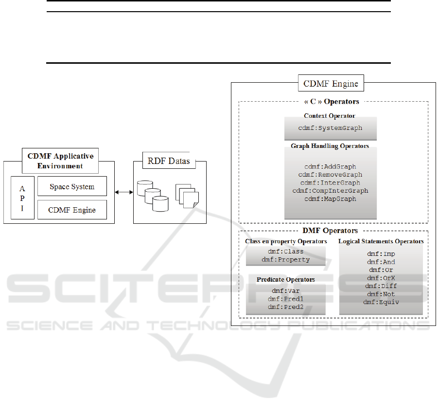
Table 1: The 3 levels of the data modeling of DMF.
Model Schema Instance
dmf:Class type dmf:Class
dmf:Property type rdf:Property
:Building type dmf:Class
:Storey type dmf:Class
:contains type dmf:Property
:b1 type :Building
:e1 type :Floor
:e2 type :Floor
:b1 :contain :s1
:b1 :contain :s2
Fig. 1. presents the composition of this
architecture of the CDMF environment which is
made of the space system stack, the API and the
engine. This environment allows the creation of
specific applications that permit to deal with facility
management requirements.
Figure 1: This is the architecture of the CDMF
environment which is made of a space system stack, an
API and an engine. RDF is used to define the data
modeling.
1. The Space System is used to configure the
system and to allow data access. It is based on an
RDF document. This space system contains a set
of graphs called SystemGraph. From this point,
the CDMF engine checks the declared graphs
and responds to queries executed from the API.
2. The API CDMF is a set of methods used to
handle the data system. This API proposes to
access data with two main classes called
SystemSetGraph and SystemGraph. The first one
allows to access the system graph which
composes the space system. The second one is
made of methods that permit to modify system
data. For instance, the method
SystemGraph.create() provides the list of Class
elements and Property elements which can be
created.
3. The CDMF engine is the kernel of the
architecture. This engine uses a space system to
configure and to know the set of systems to use.
The engine contains processes which manage
methods of the API CDMF. The engine selects
the system graphs in the space system, and
creates data, deletes data, etc. This engine is
presented in Fig. 2.
Figure 2: The CDMF engine is composed of two parts:
The DMF stack which defines modeling operators and the
C stack which defines context definition and graph
manipulation operators.
4.1 DMF: A Reduced Set of Modelling
Operators
This section presents the DMF stack. This stack is
made of operators which allow to model information
(from simple and monovalued attributes to complex
3D objects) into semantic graphs. This section
enables us to show that the formalism that we have
defined has a restricted set of operators. We show
that these operators can be combined to meet all the
needs for semantic modeling defined in the
statements. For each operator we give its equivalent
in SWRL or OWL.
• “dmf:Class” defines a class. The equivalent
operator in OWL is “owl:Class”.
• “dmf:Property” carries out the definition of a
property of a Class.
WEBIST 2010 - 6th International Conference on Web Information Systems and Technologies
24

• “dmf:Equal” defines the equality between two
variables. This operator makes it possible to test
if two resources are equivalent.
• “dmf:Var” makes it possible to define variables
used in the logical formulas. Its equivalent is
defined in SWRL by the operator
“swrl:Variable”.
• “dmf:Pred1” makes it possible to define unary
predicates. Its equivalent is defined in SWRL by
“swrl:ClassAtom”.
• “dmf:Pred2” makes it possible to define binary
predicates. The equivalent operators in SWRL
are “swrl:IndividualPropertyAtom” and
“swrl:DatavaluedPropertyAtom”. A binary
predicate is a property with a subject and an
object. To make the correspondence with RDF,
the terms of subject and object are used in order
to define the first and last element of a triplet
RDF.
• “dmf:Equiv” makes it possible to define that
two classes are equivalent. The set of the
elements of the type A is equivalent to the set of
the elements of the type B. The equivalent
operator in OWL is “owl:equivalentClass”.
• etc .
4.2 Context and Mapping Operators
This section presents the operators defined in the
stack C. These operators are used to handle graphs
and to define contexts. With these operators, new
graphs can be generated by combination of existing
graphs. These operators are commonly used to
update the data model definition when a norm in
architecture is upgraded. For example, the IFC norm
has been updated six times since 2000. Moreover,
These operators allow the semantics handling of the
3D objects contained in the graphs. The results of
this handling are directly visible in the 3D scene
which is dynamically updated. The elements defined
in this part use the space of name cdmf. For each
type of graph we present its definition by using
DMF operators.
4.2.1 Union Operator
The result of the addition of G1 and G2 is the union
of the set of the triplets of G1 and the set of the
triplets of G2. The operator of a union of graphs is
defined by the class “cdmf:AddGraph”. It has a
property “cdmf:args”. This property is a list of RDF
elements (“rdf:Bag”) whose elements are graphs.
The definition of these elements allows the union of
two or several graphs.
4.2.2 Intersection Operators
The intersection operator can be defined in different
manners and can imply a different result according
to the type of intersection carried out. The
intersection operator is defined by two elements
“cdmf:InterGraph” and “cdmf:CompInterGraph”.
The first element defines a “traditional” intersection.
The second element makes it possible to specify on
which elements of a triplet the intersection is carried
out.
Traditional Intersection. The result of the
intersection between G1 and G2 is the set of the
identical triplets in G1 and G2. This operator has
two properties “cdmf:arg1” and “cdmf:arg2”. These
two properties are “CdmfGraph” types representing
the two graphs on which the intersection must be
computed.
Composed Intersection. The composed intersection
makes it possible to determine which part of the
triplet is concerned in the calculation of the
intersection. In the case of the “traditional”
intersection, one carries out the intersection on the
set of triplets of each graph. Here we can compose
the intersection with the various parts of a triplet
(subject, object). Below you will find possible
combinations of intersections.
• The intersection on the subject in the two
graphs. The result of the intersection between
G1 and G2 is the set of the triplets whose
subjects are identical in G1 and G2.
• The intersection on the object in the two graphs.
The result of the intersection between G1 and
G2 is the set of the triplets whose objects are
identical in G1 and G2.
• The intersection on the subject of the triplets of
a graph with the object of the triplets of the
other graph. The result of the intersection
between G1 and G2 is the set of the triplets
whose subjects of the graph G1 are identical to
the objects of the graph G2.
• The intersection on the subject or the object.
There is a last combination which is actually the
addition of two intersections. The result of the
intersection on the subject of G1 and the subject
or the object of G2 is equivalent to the sum of
the intersections on the subject of G1 and G2,
and on the subject of G1 and the object of G2.
The intersection operator
“cdmf:CompInterGraph” has two properties
“cdmf:arg1” and “cdmf:arg2” which are the two
ACTIVE3D: SEMANTIC AND MULTIMEDIA MERGING FOR FACILITY MANAGEMENT
25
graphs on which the intersection is carried out. It has
two additional properties “cdmf:on1” and
“cdmf:on2” respectively defining the two parts of
the triplets used to carry out the calculation of an
intersection.
4.2.3 Difference Operator
The difference between two graphs is indicated by
the element “cdmf:RemoveGraph”. The result of the
difference between G1 and G2 is the suppression of
the set of the triplets of G2 in The class
“cdmf:RemoveGraph” has two properties
“cdmf:src” and “cdmf:rem”. The second property
constitutes the set of the triplets to be withdrawn
from the graph indicated by the first argument.
4.2.4 Mapping Operator
The last type of operation on the graphs is the
operation of mapping described by the element
“cdmf:MapGraph”. A graph of mapping is a
transformation of a graph into another graph using
mapping rules;
The mapping operator has two properties
“cdmf:src” and “cdmf:map” indicating the source
graph and the target graph. The result of the
operation of mapping is the set of the triplets which
is defined by the rules of “Gmap”. A rule in Gmap is
described by an operator of implication.
In this part we have studied five operators which
allow carrying out various combinations of graphs.
These five operators are the union, the difference,
the intersection (traditional and composed) and the
mapping. They constitute the first part of the C
stack. The second part of the C operators is the
definition of a particular graph “SystemGraph”. This
element associates various types of information with
a graph. This element is used to represent contexts.
4.3 Context Modelling, the Element
SystemGraph
The element “cdmf:SystemGraph” uses the
mechanism of Named Graphs to define the contexts
with the help of the properties. The “SystemGraph”
element associates with the graphs presented above
all useful information which is needed to respond to
the set of problems met in facility management. This
element defines the nature of the graph, on which a
graph data model is based. The element also defines
the context of use and actions that can be realized on
this graph.
“SystemGraph” evokes the data model on which
the associated graph is built. For instance, the
definition of building X is based on a data model
that describes the composition of a building. The
data model allows to check the data coherence of the
associated graph and allows to indicate which kind
of data can be generated in the graph. This data
model is defined with the help of operators
introduced in DMF. In fact, the “SystemGraph”
defines actions that can be undertaken on the graph
such as reading, writing or deleting. This can be
done according to the actions which are authorized
on the associated graph. The description of the
context in “SystemGraph” is a list of RDF
resources. This section presents the definition of
“SystemGraph” with its properties: “cdmf:model”,
“cdmf:of”, “cdmf:action”, “cdmf:graph”. The name
space cdmf is used to present these elements. An
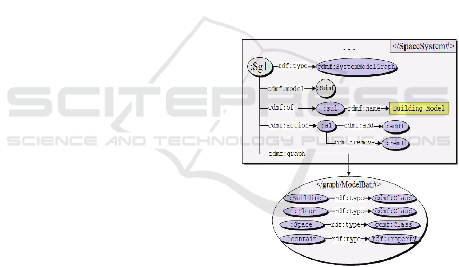
example is given in Fig. 3.
4.3.1 The Property “cdmf:model”
Figure 3: An initial “SpaceSystem” used at the beginning
of a facility management project to define the data model
that will support a building definition. There can be found
the properties “cdmf:model”, ”cdmf:of”, “cdmf:action”,
“cdmf:graph”.
This property defines the model on which a
“SystemGraph” element is based. The associated
model will be used to define the objects and the
properties which can be generated in the
“SystemGraph” graph. Subsequently, it is possible
to check the data coherency by comparing it to the
model. “SystemGraph” has a model which is also a
WEBIST 2010 - 6th International Conference on Web Information Systems and Technologies
26

“SystemGraph”. CDMF defines a class
“cdmf:SystemModelGraph” to represent a specific
“SystemGraph”. This type of “SystemGraph”
contains definitions of classes, properties and rules
defined in the syntax DMF.
4.3.2 The Property “cdmf:of”
The property “cdmf:of” defines the subject of the
“SystemGraph” element. This property defines the
context. It associates a set of RDF resources which
resume what is described by the SystemGraph. For
instance, “SystemGraph” can be the description of a
data model in the building field. “SystemGraph” can
be a data model in a certain version or
“SystemGraph” can represent data on a certain date
and in a certain language, for a certain user. It can
also define the nature of the graph and the conditions
that have to be fulfilled in order to be able to access
a graph system.
4.3.3 The Property “cdmf:action”
The property “cdmf:action” determines the actions
authorized on the graph. It defines the actions of
writing, suppression and modification. If no action is
associated to the system, this implies that only the
visualization of information is possible.
4.3.4 The Element “cdmf:Action”
The element “cdmf:Action” determines which
actions are possible, on which part of the data and
starting from which model.
An action has one or two properties. If it has only
one property add then the addition is allowed. If it
has only one property remove then the system
allows the deletion of data. If it has the two
properties, we can add and remove data in the graph
system. An element “cdmf:Add” defines which
information we can add (“cdmf:model”) and where
it has to be added (“cdmf:addIn”)
4.3.5 The Element “cdmf:Remove”
An element “cdmf:Remove” indicates the
suppressible data which have to be removed. If it
does not have this property, all the data of the graph
of the system can be deleted. The property
“cdmf:from” binds an element of the “cdmf:From”
type. According to the origin of the suppression
(“cdmf:graph”), this element defines the action to be
realized: either an addition in a
“cdmf:RemoveGraph”, or a suppression in the graph
“cdmf:graph”.
4.3.6 The Property “cdmf:graph”
The property “cdmf:graph” contains the associated
graph representing the data. The associated graph is
a “Cdmf:Graph” type. “SystemGraph” has an
attribute of the “Cdmf:Graph” type. Thus,
“SystemGraph can refer to all the types of graphs
presented in CDMF.
5 ACTIVE3D FACILITY SERVER
This section presents the Active3D Facility Server, a
web collaborative platform dedicated to the facility
management, taking into account all aspects of the
building’s lifecycle. Due to the lack of space, we
will illustrate only our proposal with two examples
of use. The first example concerns the initialization
of a space system when a facility manager needs to
configure the platform. This extension is realized by
defining a specific model. This model will be used
in the building definition process. The second point
illustrates the use of context to display specific
information to users.
5.1 Configuration of a SpaceSystem
In facility management, various versions of the
building can be managed and presented to different
actors in many countries. The representation of a
building mixes textual and graphic representations.
The first step in facility management consists in
creating the data model. A building description will
be generated starting from this model. The new data
model is created from a new applicative
environment. An initial space system is created.
Following this step, the facility manager can store
his data in the graph and has the possibility to create
data starting from “SystemGraph” ’Space System’.
The creation of “SystemGraph” includes a model, a
context (list of resources) and the graph of data. For
the model, the facility manager has to choose among
the “SystemModelGraphs” available. A
“SytemModelGraph” element is a “SystemGraph”
whose characteristic it is to contain models in its
associated graph. A SystemModelGraph represents
only a DMF model. For the context, the list of
resources contains only one resource where the
representation is ‘Building Model’.
For the associated graph, the facility manager
creates a new RDF graph which will contain the
definition of the model. For AEC projects, we have
based our model definition on the IFC 2X3. This
ACTIVE3D: SEMANTIC AND MULTIMEDIA MERGING FOR FACILITY MANAGEMENT
27
model contains approximately 600 classes (IAI,
2007), (IFC, 2007). The following snapshot presents
a part of the IFC model in the application. This
model is created with the tools proposed by the
application (creation of classes and properties).
Fig. 4 presents a snapshot of an IFC building.
Each IFC object is represented in the Building
Model by an operator “dmf:Class”. IFC links are
represented by an operator “dmf:Property”. From
this “SystemGraph”, we can declare classes,
properties, rules, etc. In this example, we have
created simply three classes which are “Building,
Floor” and “Space” and a property “contain”.
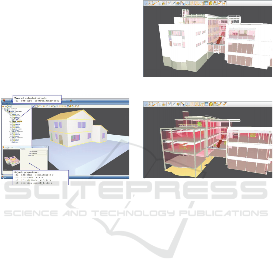
Figure 4: An example of a 3D view of a building object in
a Facility Management view using DMF operators.
5.2 Context Representation
From the ”SystemGraph” element, the facility
manager defines a view on data according to a
specific context. This context can be linked to a
specific step in the building’s lifecycle or it can be
linked to a specific type of user (for example
plumbers, architects or structure engineers).
In the Active3D collaborative platform, this context
is used to build user models that define data,
operators and interface for a specific user. Thus,
during the identification protocol, when a user tries
to connect himself to the platform, a specific graph
is built and a view of a building is built according to
its context. Figures 5 and 6 show two different views
of the same building according to the Architect view
and the Structure Engineering view respectively.
6 CONCLUSIONS
In this paper we have presented a Semantic Web
approach for facility management. This approach
Figure 5: Architectural view of a building. In this snapshot
it is required to display the walls for the architect.
Figure 6: A structural view of a building. This view is
required for structure engineers. The corresponding graph
provides all elements needed to make structure
calculations.
allows facility managers to support the building’s
lifecycle management from the design to the
destruction of the building in a collaborative context.
Several actors provide and handle building
information. This approach is based on a semantic
model called CDMF and the IFC 2x3 standard
which defines the 3D geometries of the objects of
building. CDMF improves data management during
the lifecycle of a building. Our proposition, based on
graph combinations and the contextual element
“SystemGraph”, addresses the problem of model
evolution, of data mapping, of the management of
temporal data, and of the adaptation of data
according to the use and the user. Our framework
facilitates data maintenance (data migration, model
evolution) during the building lifecycle and reduces
the volume of data.
A collaborative Internet platform was developed
to support the building’s lifecycle. This platform is
mainly used to federate all the actions realized on a
building during its lifecycle, to merge all
information related to these actions in an adaptive
hypermedia graph, to extract some trade views of the
building by combining information collected during
WEBIST 2010 - 6th International Conference on Web Information Systems and Technologies
28

the lifecycle from heterogeneous sources and to
handle all these views through a dynamic and
adaptive 3D interface. Currently, the Active3D
platform supports more than 100 specific building
information systems where more than 400 actors
from all civil engineering domains collaborate at
each step of the building’s lifecycle.
REFERENCES
Autodesk White Paper: Building Information Modelling,
(Available online at: http://images.autodesk.com/
apac_sapac_main/files/4525081_BIM_WP_Rev5.pdf),
2002
Barrett P., Baldry D., 2003. Facilities Management,
Towards Best Practice, Blackwell Publishing, ISBN
0632064455
Bizer C., Cyganiak R., 2005, NG4J Named Graph API for
Jena, http://sites.wiwiss.fu-berlin.de/suhl/bizer/ng4j/
Carroll J.J., Bizer C., Hayes P., Stickler P., 2005. Named
Graph, Provenance and Trust, http://www2005.org/
cdrom/docs/p613.pdf
Cruz C., Nicolle C., 2006. Active3D: Vector of
Collaboration, Between Sharing and Data Exchange,
INFOCOMP, Jounal of Computer Science, 5 (3), pp.
1-8, January, 2006
Dace A. Campbell., 2007. Building Information Modeling:
The Web3D Application for AEC, ACM Web3D,
Perugia, Italy, (2007)
Eastman C., Wang F., You S. F., Yang D., 2005.
Deployment of an AEC industry sector product model,
Computer Aided Design, Vol.37, No.12, pp. 1214-
1228, 2005
Guha R.V. and Fikes R., 2004, Context for the semantic
web. In Proceedings of ISWC’2004
Guha R.V.: Contexts, 1995, A Formalization and Some
Applications. PhD thesis
Horrocks I., Patel-Schneider P.F., Boley H., Tabet S.,
Grosof B., Dean M., 2004. SWRL: A Semantic Web
rule Language: Combining OWL and RuleML,
http://www.w3.org/Submission/SWRL/
IAI, http://www.iai-international.org, 2007
IFC 2x3 Workshop, Boston, USA, March 19, 2007,
http://127.0.0.1:4664/redir?url=http%3A%2F%2Fbuil
dingsmart%2Ecom%2Eau%2F&src=1&schema=2&s=
suabHoX9yEfSmitJzdEaD6NuyKQ
Keith A., Atkin B., Bröchnet J., Haugen T., 2004.
Facilities Management, Innovation and Performance,
Taylor and Francis Edition, ISBN 0415321468, 2004
Klein M., 2002. Interpreting XML via an RDF schema, In
ECAI workshop on Semantic Authoring, Annotation
& Knowledge Markup, Lyon, France
Klyne G., Carroll J.J., 2004. Resource description
Framework (RDF): Concepts and Abstract Syntax,
http://www.w3.org/TR/rdf-concepts/
Lee G., Sacks R. and Eastman Charles M., 2006.
Specifying parametric building object behavior (BOB)
for a building information modeling system,
Automation in Construction, Elsevier, Volume 15,
Issue 6, November, Pages 758-776, Knowledge
Enabled Information System Applications in
Construction, 2006
McGuinness D.L., Van Harmelen F., 2004. OWL
Ontology Language, Overview http://www.w3.org/
TR/owl-features/
NBIMS: National BIM Standard Purpose, US National
Institute of Building Sciences Facilities Information
Council, BIM Committee, (Available online at:
http://www.nibs.org/BIM/ NBIMS_Purpose.pdf),
52006), 2007b
NBIMS: National Building Information Modeling Stan-
dard Part-1: Overview, Principles and Methodologies,
US National Institute of Building Sciences Facilities
Information Council, BIM Committee, (Available
online at:
http://www.facilityinformationcouncil.org/bim/publi-
cations.php), 2007a
NIST CIS2 Web Site, Web Site, (Available online at:
http://cic.nist.gov/vrml/ cis2.html), 2007
SABLE Web Site, Web Site, (Available online at:
http://www.blis-project.org/~sable/), 2005
Tolman F., 1999. Product modelling standards for the
building and construction industry: past, present and
future, Automation in Construction, Vol.8, No.3, pp.
227-235, 1999
Zamanian K. M., Pittman J. H., 1999, A software industry
perspective on AEC information models for distributed
collaboration, Automation in Construction, Vol.8,
No.3, pp. 237-248, 1999
ACTIVE3D: SEMANTIC AND MULTIMEDIA MERGING FOR FACILITY MANAGEMENT
29
