
TEACHING PROGRAMMING WITH FORMAL MODELS IN
GREENFOOT
Moritz Balz and Michael Goedicke
Specification of Software Systems, University of Duisburg-Essen, Essen, Germany
Keywords:
Teaching formal methods, Teaching programming, Model-driven software development, Greenfoot.
Abstract:
Formal methods for software development are subject to teaching in computer science as a matter of course.
However, it is difficult to relate the theories to the practical matter of program code creation. The reason for
this is the complexity of model-driven software development approaches which would be needed to derive
executable applications from formal models, but are usually not in the focus of the courses. We propose to
teach formal methods by using “embedded models”, i.e. program code patterns that represent the semantics
of formal methods inside arbitrary object-oriented programs. The approach is realized within the Greenfoot
graphical simulation enginge. With this approach the technical barrier to the practical use of formal methods
is lowered, so that students can easily experiment with such models in a game-oriented environment.
1 INTRODUCTION
Teaching formal methods for software development is
important (Mili, 1983), but a difficult task. Not only
are the formal methods themselves complicated and
require abstract thinking by students. More impor-
tant, they are hard to connect to practical software
development and the every-day programming tasks.
That leads to two observations: (1) The examples be-
ing used are usually very simple, like an elevator con-
trol or a traffic light; (2) the examples are usually
realized in modelling tools only and not as program
code. This leads to the situation that teaching of for-
mal methods and of programming are in most cases
completely separated, making it hard for students to
grasp the benefits of formal methods for software de-
velopment.
Existing tools that are appropriate for teaching
purposes usually target either teaching of program-
ming or formal methods. For teaching programming,
a good example is the graphical simulation environ-
ment Greenfoot (Henriksen and Klling, 2004), which
allows with little effort to create worlds and interact-
ing entities therein, which are graphically represented
on the screen. Formal methods can be illustrated with
appropriate models like state machines, whose states
and transitions intuitively explain the purpose of sys-
tems developed based on such models. Tools like UP-
PAAL (Larsen et al., 1997) can be used in this context
that allow for graphical design, simulation and verifi-
cation of state machines.
However, a direct connection between models and
program code is hard to teach, because both abstrac-
tion levels are usually separated and hard to bridge.
This is a problem widely acknowledged in numer-
ous approaches of model-driven software develop-
ment (MDSD). In this context, the concept of embed-
ded models (Balz et al., 2008; Goedicke et al., 2009)
was proposed that connects models and programming
languages by representing the model syntax in static
program code structures. We now want to use this
approach for teaching purposes, too. In this contri-
bution we present our approach to integrate program-
ming with state machine models inside Greenfoot. An
appropriate embedded model allows to represent in-
teracting entities in Greenfoot as communicating state
machines which can be verified graphically in UP-
PAAL.
In order to do this, this contribution is structured
as follows: In section 2 we consider related work re-
garding MDSD and formal methods teaching. The
concept of embedded state machine models is briefly
introduced in section 3 and then adapted to Green-
foot simulations in section 4. Based upon this, we
show how verification of this simulation is possible
with the state machine tool UPPAAL in section 5 to
demonstrate the usefulness of our approach for teach-
ing formal methods. Finally, we give a conclusion
and a short outlook to future work, especially regard-
ing tools, in section 7.
309
Balz M. and Goedicke M. (2010).
TEACHING PROGRAMMING WITH FORMAL MODELS IN GREENFOOT.
In Proceedings of the 2nd International Conference on Computer Supported Education, pages 309-316
DOI: 10.5220/0002768303090316
Copyright
c
SciTePress

2 RELATED WORK
We consider approaches to be related to our contri-
bution that aim at bridging the gap between the dif-
ferent abstraction levels of formal models and pro-
gram code. This concerns software development
approaches as well as formal method teaching ap-
proaches.
MDSD approaches have the objective of develop-
ing high-level models and derive software from them
(Hailpern and Tarr, 2006). This could be of interest
for our purpose because it embraces different abstrac-
tion levels. Usually, code generation (Brown et al.,
2006) is used that derives program code automati-
cally from a model. This raises difficulties when the
generated code is to be integrated in non-generated
program code, for example in special environments
like Greenfoot. In addition, high-quality program
code is required for teaching purposes, but the qual-
ity of generated code varies depending on the gener-
ator tool. Model round-trip engineering (Sendall and
Kster, 2004) concepts relate generated program code
to high-level models, but are based on heuristics and
not unambiguous and therefore inappropriate for our
purpose. Executable models (Luz and da Silva, 2004;
Hen-Tov et al., 2008) interpret model descriptions in-
dependent from programming languages. While this
is a clean single-source approach and also suited to
demonstrate software execution based on high-level
models, it is difficult to express all business logic of a
program in high-level models. For teaching purposes,
this is also not helping to demonstrate the intercon-
nections between formal models and programming.
Approaches for teaching formal methods usually
work at higher levels of abstraction and without com-
prising program code, as stated in the introduction.
When program code is considered, the objective is
usually to verify its correctness by means of for-
mal methods, but at a low level of abstraction. Ex-
amples for this are the formal specification of al-
gorithms (McLoughlin and Hely, 1996; Bubel and
Hhnle, 2008) and specification of protocols (Brakman
et al., 2006). Similar, model checking of program
code (Roychoudhury, 2006) is related to the low-level
semantics of the programming language and thus not
appropriate for teaching the interconnections to high-
level models.
In summary, there is a lack of approaches that
work on multiple levels of abstractions at the same
time and illustrate the relations. This is especially
true with respect to tools appropriate for teaching pur-
poses: MDSD approaches and techniques make as-
sumptions about program code structures and are thus
hard to integrate in special frameworks like Greenfoot
that make conflicting assumptions.
3 EMBEDDED STATE MACHINES
In the last years, approaches were developed that con-
sider program code not only with respect to the se-
mantics of the programming language, but also with
respect to higher-level semantics that can be influ-
enced by the developer. This applies to so-called
internal DSLs (Fowler, 2006), i.e. domain-specific
languages that are embedded in general-purpose lan-
guages (host languages) and provide semantics of
DSLs there. Furthermore, attribute-enabled program-
ming (Schwarz, 2004) uses the capability of modern
programming language versions to incorporate type-
safe, compiled meta data to annotate source code frag-
ments.
Embedded models (Balz et al., 2008; Balz et al.,
2009) build on these concepts to relate program code
fragments to abstract models like state machines.
When an appropriate program code pattern is defined,
different abstraction levels are maintained in the same
program code. Access to the fragments is not only
possible at development time, but also at run time by
means of structural reflection (Demers and Malenfant,
1995). This allows to create an execution framework
that accesses and invokes the fragments.
3.1 Model and Program Code Pattern
The model type we will use for teaching purposes are
in this case state machines. The language chosen for
this implementation is Java (Gosling et al., 2005) with
its Annotations enhancement for meta data inclusion
(Sun Microsystems, Inc., 2004). The program code
pattern is illustrated in 1. The class at the top repre-
sents a state with the class name being the name of
the state. The method in the state class represents a
transition. It is decorated with meta data referring to
the target state class and a “contract” class containing
guards and updates. An instance of an interface type
referred to as “actor” that encapsulates the applica-
tion’s business logic is passed to transition methods.
Its methods are interpreted as action labels since they
are called when the transition fires.
Guards and updates are implemented as two meth-
ods in a so-called “contract” class which is shown at
the bottom of figure 1. Both evaluate expressions to
a boolean value. The guard uses the current variable
values of the state machine to determine if a transition
can fire, the update compares the current values with
the values from the point in time before the transi-
tion fired to determine the changes to the state space.
CSEDU 2010 - 2nd International Conference on Computer Supported Education
310
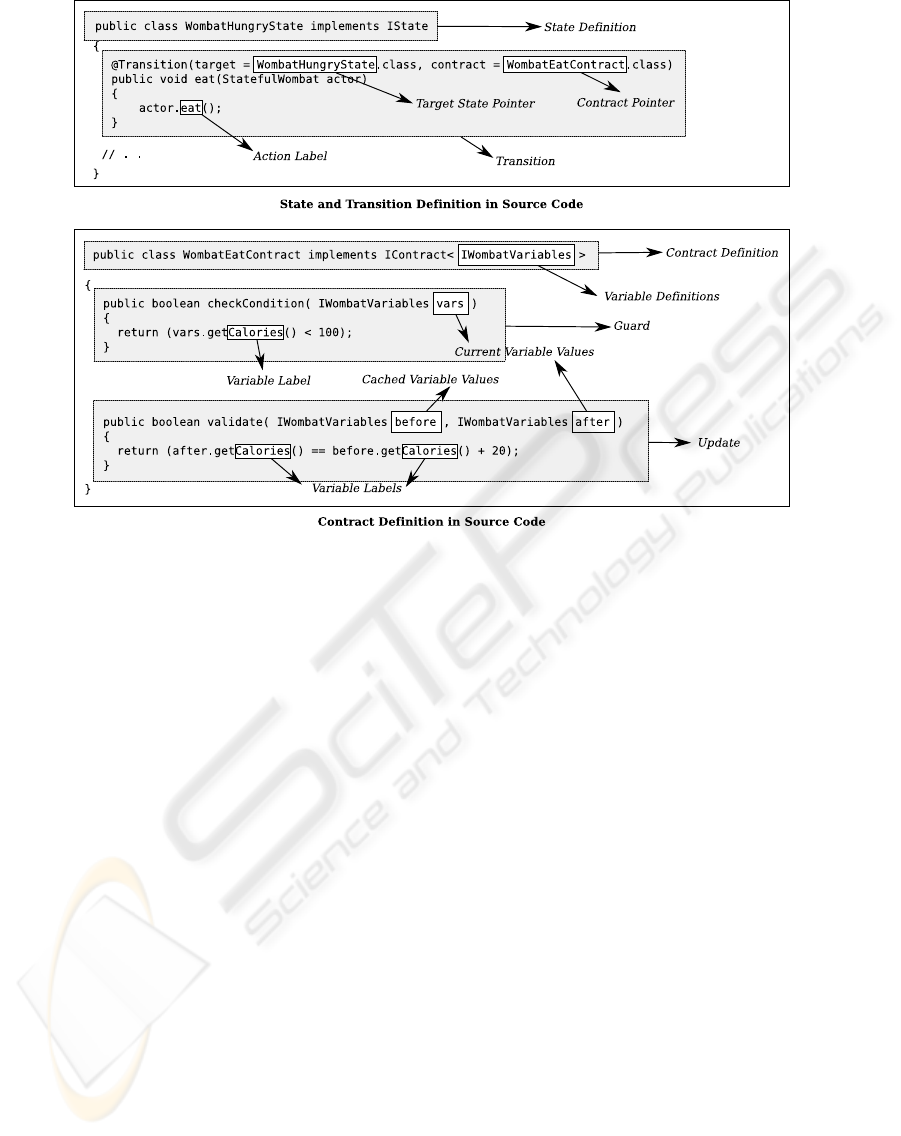
Figure 1: The program code pattern with the program code itself and the related state machine model semantics. At the top, a
state class and an emanating transition can be seen. At the bottom, the related guard and update are depicted. These structures
are unambiguous so that the complete state machine model can be extracted.
Both methods access for this purpose a “variables”
type which is a facade type representing the variables
constituting the state space of the state machine. This
type contains “get” methods for each variable, which
are by this means defined with a label and a data type.
In addition, channels can be represented by
classes implementing a given interface
IChannel
containing a method
enable
. This method provides
the channel class with a list of all transitions that try to
send and receive on this channel and allows to chose
a pair of them. It can in addition execute any busi-
ness logic on the given actors to notify them that this
channel was selected.
3.2 Execution
At run time the state machine model contained in the
program code pattern is executed by a small frame-
work. This framework takes basically a set of initial
state, variables implementation and actor implemen-
tation for each state machine and executes the state
machines roughly as follows:
1. All transition methods in the current state of each
state machine that want to send or receive on
channels are considered. They fire when the guard
evaluates to
true
and the related channel allows
them to fire.
2. For all other states, one transition method whose
guard evaluates to
true
is invoked.
3. The updates of all invoked transitions are called to
validate the transition execution.
4. For each transition invoked, the target state is set
and the procedure repeated until each machine
reaches a finite state, i.e. a state without transi-
tions.
This execution algorithm thus interprets the static
program code structures so that a sequence of actions
is created that matches the execution semantics of a
state machine model. The program code pattern man-
ages a separation between well-defined model seman-
tics and arbitrary business logic: Execution control is
passed to application components in transition meth-
ods as well as inside the variable interface implemen-
tation and returns to the state machine accordingly.
4 IMPLEMENTING STATE
MACHINES IN GREENFOOT
The objective of this contribution is to create a con-
nection between different abstraction levels for teach-
TEACHING PROGRAMMING WITH FORMAL MODELS IN GREENFOOT
311

ing formal methods. The higher level of abstraction
level is that of UPPAAL state machine models, which
can be verified and simulated. It requires the exis-
tence of precise models defining states, transitions,
variables, and channels. The low abstraction level is
that of programming in Greenfoot, which requires the
student to write detailed algorithms that address the
specifics of the simulation environment. This includes
controlling the graphical appearance of the simulation
world and its entities as well as accessing their prop-
erties, for example to find intersecting entities.
4.1 Concept
The design of Greenfoot can roughly be summarized
as follows: A world provides the background for the
simulation. This includes the size and graphical ap-
pearance of the visual background, and allows to ac-
cess all entities currently available in this world. Sin-
gle entities can move, change their appearance, and
gather information about their vicinity in the world.
Apart from that, they can implement almost arbitrary
business logic. Actions in Greenfoot are performed in
cycles. In each cycle, a pre-defined method “act” of
each entity and the world is called. In this method, the
objects must determine their current state and decide
which actions to take. If and how often these cycles
are called is controlled by the user and can thus not
be influenced by the objects running in the simula-
tion. This concept is easy to map to the execution of
embedded state machines as described in section 3.2:
• A state machine corresponds to a single entity in
the simulation. The fact that the entities must
know about their current state complies to explicit
states of a state machine.
• The decisions that are made based upon a certain
state can be represented by outgoing transitions.
• The actions that modify the system state in transi-
tions correspond to action labels.
• A system of communicating state machines corre-
sponds to a world containing different entities that
can interact.
In this section we will describe the implementa-
tion of a Greenfoot simulation called “Stateful Wom-
bats”, which is adapted from Greenfoot’s default
“Wombats” example. Our simulation has the follow-
ing rules:
• The world has two interacting types of objects,
wombats and leafs. The interaction is that wom-
bats eat leafs when they are hungry and find them.
• Wombats determine if they are hungry by the
number of calories they have eaten. They are hun-
gry with less than 100 calories. Whenever they eat
a leaf, they gain 20 calories. When wombats are
hungry, they appear walking randomly through
the world.
• When wombats are fed, i.e. the numberof calories
equals 100, they stop eating and digest until the
number of calories reaches 0. In every cycle, a
wombat digests 5 calories. As long as a wombat
digests, it is laying on its back and does not move.
• When a leaf is added to the world, it is fully
grown. This is determined by the variable
growth
having the value 100. When a leaf is grown, it
appears in the simulation in its normal size.
• When a leaf is eaten, its growth is set to 0. From
now on, leafs start to grow by 1 in every cycle.
They do not appear visually at all.
• When the growth reaches 50, the leaf is consid-
ered half-grown. It appears in a smaller size in the
world again, but continues to grow until its growth
reaches 100 again.
The two Greenfoot actors, wombats and leafs,
contain their “business logic” that manages calories
and growth and also determines if wombats and leafs
intersect. The running simulation in Greenfoot with
its actors can be seen in figure 2.
4.2 Greenfoot World
With these principles, a world is the foundation of ev-
ery embedded state machine in Greenfoot. Figure 3
contains the implementation of an exemplary world
we will use now to present the realization of our con-
cept in Greenfoot. In the constructor of the world,
a super constructor is called that constitutes the size
of the visual background. Afterwards, an object of
the type
EmbeddedStateMachineSystem
is created,
which represents the system of communication state
machines. Added to this system is a channel deciding
if objects can interact with each other. In the world,
no state machine itself is added to the system. This
will be done for each entity instance separately. Most
important in the world class is the
act
method that in-
tegrates the state machine system to Greenfoot: In ev-
ery cycle, the next step of the system is called, which
invokes the next transition for each entity by consid-
ering the channels, if applicable.
4.3 Actors
The source code of the wombat is shown in figure
4. Its purposes are to manage the calories (methods
eat
and
digest
), to manage the appearance (meth-
ods
beginDigest
and
getHungry
), and to deter-
mine if leafs are available (method
canEat
). The
CSEDU 2010 - 2nd International Conference on Computer Supported Education
312
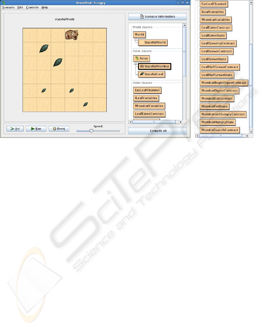
Figure 2: The communicating state machines as running in Greenfoot. The wombat is currently in the “hungry” state. The
large leafs are in the state “grown”, the small leafs in the state “halfgrown”. Some leafs are currently not visible at all because
they are in the state “eaten”. Right hand one can see the classes constituting the system: The two actors, and the “other
classes” with the actual states, transitions, contracts and channels of the state machine.
appearance and the interaction with other objects
are business logic that is specific to Greenfoot and
thus hard to represent in any formal model at all.
These methods represent everything a wombat can
do, however, they do not trigger any actions. The
actual sequence of actions at run time is determined
by a state machine, which is created and registered
in the world in the wombat’s constructor. Accord-
ing to the rules defined in section 4.1, the wom-
bat is modeled with two states – one for the wom-
bat being hungry (class
WombatHungryState
), and
one for the wombat being fed and digesting (class
WombatFedState
). The model is shown in figure 5.
It references the state classes as well as the chan-
nel class
EatLeafChannel
, in this case for send-
ing. The variable
calories
used in the guards and
updates refers to the method
getCalories
of the
interface
IWombatVariables
, which defines the re-
lated method of the
StatefulWombat
class as a vari-
able. The channel class invokes the wombat’s
canEat
method and thus accesses the Greenfoot-specific busi-
ness logic to determine if the state machines can com-
municate.
The implementation of the leaf is analogous as
shown in figure 5. The states comply to the require-
ments defined in section 4.1 with the variable influ-
encing the guards called
growth
. The channel is also
accessed, but receiving. In summary, it is possible to
create complete interacting state machines in the pro-
gram code pattern which can be run in Greenfoot.
5 VERIFICATION
In section 4 we described how embedded models can
be used to teach programming by using a model sys-
tematically to derive an implementation of it. The vi-
sualization that is possible with UPPAAL is of most
interest. In addition, UPPAAL provides a simulator
that visualizes each step of a running state machine
and visualizes current states, activation of transitions,
and current variable values. This is already desirable
as it makes the influence of the model on the program
comprehensible and thus makes manual verification
possible.
However, teaching formal methods should con-
sider formal properties of the related models that al-
low for automated verification. For the given imple-
mentation, the verification feature of UPPAAL can be
used to verify not only the state machines themselves,
but at the same time the program code containing the
state machine. The separation of model and busi-
ness logic in the program code defines starting points
for this: On the one hand the variables being used
in guards and thus controlling the program flow, and
TEACHING PROGRAMMING WITH FORMAL MODELS IN GREENFOOT
313
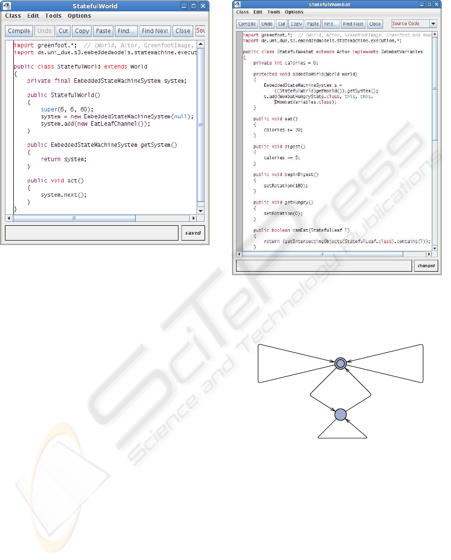
Figure 3: The source code of the Greenfoot world. Since
a system of communication state machines is being used,
it must be controlled from the world instance in order to
coordinate the single actors. The system is created at the
beginning by providing a listener that is notified about failed
contract validations and the channel that coordinates if a
leaf can be eaten by a wombat.
on the other hand the updates that constitute how the
state space is expected to change during transitions.
The example introduced above relies on the two
variables
calories
and
growth
for wombats and
leafs, which have clear ranges in this example. The
verifier can thus, for example, be used to ensure that
both variables never exceed the range [0, 100]. Figure
7 shows the query and the results for the given model.
This verification can be used to track errors in the
guards and updates. These, in turn, determine the pro-
gram flow and validate the business logic. In our tests,
the most common errors that could be found using the
verifier were caused by the usage of wrong operators
in guards and updates, for example with the expres-
sion
growth < 100
instead of
growth <= 100
.
6 EVALUATION
From a theoretical point of view, the approach is suc-
cessful: The program code structures can not only
represent the model syntax, but also be integrated in
Greenfoot seamlessly. Different to other modeling
techniques, the use of a special environment for teach-
Figure 4: The source code of the leaf actor with the overrid-
den method that initiates the state machine and the methods
providing the business logic of a leaf.
WombatFedState
WombatHungryState
calories > 0 calories = calories - 5
calories == 0
calories == 100
calories < 100
calories < 100
EatLeafChannel!
calories = calories + 20
Figure 5: The state machine controlling the wombat’s be-
havior as extracted from the program code and edited in
UPPAAL.
ing purposes is thus possible. Considering state ma-
chines, the related program code is separated: On the
one hand we have “business logic” that is specific to
Greenfoot and its simulations, in our case the Wombat
world. On the other hand, external classes exist that
represent the state machine and are responsible for de-
termine the current state of the application, deciding
which actions to take, and invoking the related busi-
ness logic. Although this leads to a higher effort when
the related classes must be created, an existing tool al-
lows to extract the model into UPPAAL to allow for
CSEDU 2010 - 2nd International Conference on Computer Supported Education
314
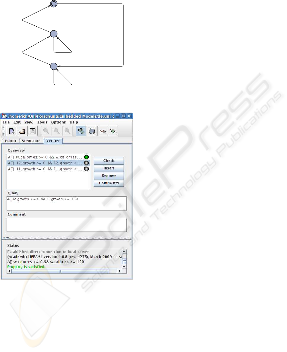
LeafHalfGrownState
LeafEatenState
LeafGrownState
growth < 50
growth = growth + 1
growth < 100
growth = growth + 1
growth == 100
growth >= 50
growth == 100
EatLeafChannel?
growth = 0
Figure 6: The state machine controlling the leaf’s behavior
as extracted from the program code and edited in UPPAAL.
Figure 7: The UPPAAL verifier used to ensure the range for
the variables
calories
and
growth
.
visual feedback. This does not only structure the pro-
gram design and implementation, but also perfectly
matches the purpose of a state machine model. The
state machine itself can be visualized and its function-
ality comprehended easily.
In addition to supporting the design, the formal
foundation of models like state machines is of course
of interest for teaching formal methods: Using an ap-
propriate tool, students can detect errors and incon-
sistencies not only in the model, but also in the appli-
cation. At the same time, they can refer to the visual
simulation in Greenfoot to see the practical influence
of the model’s properties on the simulation. From our
point of view, the concept is already appropriate to
teach development with formal models.
The practical evaluation will consist of two steps.
First, the approach will be introduced as described
here in a formal methods course at our working group
in the next year. We will rely on manual programming
this time, thus requiring the students to deal with the
program code pattern in detail. A tool will be avail-
able that extracts the UPPAAL model from the pro-
gram code afterwards to visualize, simulate and verify
it. The second step work will include an enhancement
of Greenfoot to integrate a visual editor that manages
the program code structures. This editor will also
allow to extract the model more easily to UPPAAL.
We also plan to create a monitoring tool that visual-
izes the executed state machines, their variables, and
their interactions at run time. The two steps will be
compared afterwards considering the practical under-
standing the students gain regarding the programming
as well as the use of formal methods.
7 CONCLUSIONS
In this contribution we presented an approach to teach
formal methods for software engineering by combin-
ing the game-oriented visual simulation environment
Greenfoot with the state machine model checker UP-
PAAL. The key to this combination is the concept of
embedded models which represent the syntax of for-
mal models in well-defined program code patterns.
Formal models can thus be integrated in arbitrary pro-
gram code, even within a specific environment like
Greenfoot. An execution framework that can run the
state machine by using reflection mechanisms of Java
is integrated in Greenfoot and controls the actors and
their interactions.
This approach is successful from our point of view
because different abstraction levels can be combined
and the use of formal models for software develop-
ment can be illustrated to students. Not only does the
approach facilitate a separation of business logic and
the controlling model. It also allows to visualize, sim-
ulate and verify the state machine model. Since it is
embedded in program code, students can thus easily
gain feedback regarding the correctness of model and
business logic. Future work will include the devel-
opment of appropriate tools. With these we intend to
make programming with formal models an integrated
part of computer science teaching and lead students to
gain insight to the practical use of formal models.
TEACHING PROGRAMMING WITH FORMAL MODELS IN GREENFOOT
315

REFERENCES
Balz, M., Striewe, M., and Goedicke, M. (2008). Embed-
ding State Machine Models in Object-Oriented Source
Code. In Proceedings of the 3rd Workshop on Mod-
els@run.time at MODELS 2008, pages 6–15.
Balz, M., Striewe, M., and Goedicke, M. (2009). Embed-
ding Behavioral Models into Object-Oriented Source
Code. In Software Engineering 2009. Fachtagung
des GI-Fachbereichs Softwaretechnik, 2.-6.3.2009 in
Kaiserslautern.
Brakman, H., Driessen, V., Kavuma, J., Bijvank, L. N.,
and Vermolen, S. (2006). Supporting Formal Method
Teaching with Real-Life Protocols. In Formal Meth-
ods in the Teaching Lab – A Workshop at the Formal
Methods 2006 Symposium, pages 59–67.
Brown, A. W., Iyengar, S., and Johnston, S. (2006). A Ra-
tional approach to model-driven development. IBM
Systems Journal, 45(3):463–480.
Bubel, R. and Hhnle, R. (2008). A Hoare-Style Cal-
culus with Explicit State Updates. In Proceedings
of Formal Methods in Computer Science Education
(FORMED2008), pages 49–59. Elsevier.
Demers, F.-N. and Malenfant, J. (1995). Reflection in logic,
functional and object-oriented programming: a Short
Comparative Study. In Proceedings of the IJCAI’95
Workshop on Reflection and Metalevel Architectures
and their Applications in AI, pages 29–38.
Fowler, M. (2006). InternalDslStyle.
http://www.martinfowler.com/bliki/InternalDslStyle.html.
Goedicke, M., Striewe, M., and Balz, M. (2009). Sup-
port for Evolution of Software Systems using Embed-
ded Models. In Design for Future – Langlebige Soft-
waresysteme.
Gosling, J., Joy, B., Steele, G., and Bracha, G. (2005).
Java
TM
Language Specification, The 3rd Edition.
Addison-Wesley Professional.
Hailpern, B. and Tarr, P. (2006). Model-driven develop-
ment: The good, the bad, and the ugly. IBM Systems
Journal, 45(3):451–461.
Hen-Tov, A., Lorenz, D. H., and Schachter, L. (2008). Mod-
elTalk: A Framework for Developing Domain Spe-
cific Executable Models. In Proceedings of the 8th
OOPSLA Workshop on Domain-Specific Modeling.
Henriksen, P. and Klling, M. (2004). greenfoot: Combin-
ing Object Visualisation with Interaction. In OOPSLA
’04: Companion to the 19th annual ACM SIGPLAN
conference on Object-oriented programming systems,
languages, and applications, pages 73–82, New York,
NY, USA. ACM.
Larsen, K. G., Pettersson, P., and Yi, W. (1997). UPPAAL
in a Nutshell. Int. Journal on Software Tools for Tech-
nology Transfer, 1(1–2):134–152.
Luz, M. P. and da Silva, A. R. (2004). Executing UML
Models. In 3rd Workshop in Software Model Engi-
neering (WiSME 2004).
McLoughlin, H. and Hely, K. (1996). Teaching formal
programming to first year computer science students.
ACM SIGCSE Bulletin, 28(1):155–159.
Mili, A. (1983). A case for teaching program verification:
Its importance in the cs curriculum. In SIGCSE ’83:
Proceedings of the fourteenth SIGCSE technical sym-
posium on Computer science education, pages 2–6,
New York, NY, USA. ACM.
Roychoudhury, A. (2006). Introducing Model Checking to
Undergraduates. In Formal Methods in the Teaching
Lab – A Workshop at the Formal Methods 2006 Sym-
posium, pages 9–14.
Schwarz, D. (2004). Peeking Inside the Box: Attribute-
Oriented Programming with Java 1.5. ONJava.com.
http://www.onjava.com/pub/a/onjava/2004/06/30/
insidebox1.html.
Sendall, S. and Kster, J. (2004). Taming Model Round-
Trip Engineering. In Proceedings of Workshop on Best
Practices for Model-Driven Software Development.
Sun Microsystems, Inc. (2004). JSR 175: A Meta-
data Facility for the Java
TM
Programming Language.
http://jcp.org/en/jsr/detail?id=175.
CSEDU 2010 - 2nd International Conference on Computer Supported Education
316
