
PRODUCT REPRESENTATION TO SUPPORT VALIDATION OF
SIMULATION MODELS IN COMPUTER AIDED ENGINEERING
Andreas Kain, Andreas Gaag and Udo Lindemann
Institute of Product Development, Technische Universitaet Muenchen, Boltzmannstr. 15, 85748 Garching, Germany
Keywords: Model validation, System modelling, Multiple domain matrix (MDM), Flexible multibody simulation.
Abstract: Computer aided engineering (CAE) provides proper means to support New Product Development (NPD) by
simulation tools. Simulation furthers early identification of product characteristics to reduce costs and time.
The applicability of simulation models in NPD strongly depends on their validity, thus validating a
simulation poses a major issue to provide correct experimentation results. The authors propose a matrix
based approach to combine solution neutral system representation, solution specific product representation,
and product behaviour in order to raise system comprehension to support validation of simulation models. A
case study exemplifies the suggested approach. This paper illustrates the matrix based product
representation at composing a flexible multibody simulation of a highly dynamic linear shafting machine
tool. The approach supports preprocessing and validation of a flexible multibody simulation model.
1 INTRODUCTION
New product development (NPD) nowadays grounds
on simulation tools provided by computer aided
engineering (CAE). It becomes reasonable to
evaluate engineering design in early stages before
starting physical prototyping and thus enables early
anticipation of product characteristics. Simulation
also assists further development of existing products
or establishing a line of products.
As summarized in (Musselman 1994; Robinson
and Bhatia 1995; Robertson and Perera 2002) a
simulation project comprises interpretive,
developmental, and analytical facets. Modelling
includes problem formulation, model
conceptualization, data collection, model building,
verification, validation, analysis, documentation and
implementation.
Validation requires that the model is an accurate
representation of the system being modelled taking
into account the modelling purpose (Robinson and
Bhatia 1995; Sargent 2004). The modelling purpose
includes requirements on the model itself. Reasoning
and derivation of conclusions by experimentation
with the model requires successfully model
credibility and thus completed validation. Thus
validating a simulation poses a major issue to
provide correct experimentation results. The authors
propose a matrix based system representation to
support validation of simulation models in CAE.
The paper contains in section 2 background
information. Section 3 introduces a matrix based
product representation to raise system
comprehension and thus to support system
validation in CAE. Section 4 illustrates a case study
of supporting a flexible multi body simulation in
further developing a machine tool. Section 5
discusses the application of the suggested approach
in the case study. Section 6 concludes the paper.
2 BACKGROUND
According to (Sargent 2004) analysis and modelling
derive a conceptual model based on the problem
entity which represents the system. The conceptual
model represents the system for a particular study.
Implementation of the conceptual model leads to a
computerized model. Validation of this
computerized model by operational validation
proves that the model’s output behaviour represents
sufficiently the problem entity for the model’s
intended purpose. VDI 3681 emphasises that
validation is the proof that a system satisfies the
requirements (VDI 2005). Bender narrows down the
term validation as “doing the right things” contrary
to the term specification that comprises “doing the
355
Kain A., Gaag A. and Lindemann U.
PRODUCT REPRESENTATION TO SUPPORT VALIDATION OF SIMULATION MODELS IN COMPUTER AIDED ENGINEERING.
DOI: 10.5220/0002249803550359
In Proceedings of the 6th International Conference on Informatics in Control, Automation and Robotics (ICINCO 2009), page
ISBN: 978-989-674-000-9
Copyright
c
2009 by SCITEPRESS – Science and Technology Publications, Lda. All rights reserved
things properly” (Bender 2005). Sargent summarizes
and details several validation techniques (Sargent
2004): (1) Animation, (2) Comparison to other
models, (3) Degenerate Tests, (4) Event Validity, (5)
Extreme Condition test. (6) Face Validity, (7)
Historical data validation, (8) Internal Validity, (9)
Multistage Validation, (10) Operational Graphics,
(11) Parameter Variability – Sensitivity Analysis,
(12) Predictive Validation, (13) Traces, and (14)
Turing Tests. Either the developer, or the user or a
third party conduct one or more of these techniques
either concurrently with the development of the
simulation model or afterwards.
In product development concerned with not
merely mechanical products several types of
relations connect components systematically such as
function, structure, and behaviour (Pahl and Beitz
1995; Ariyo, Eckert et al. 2006). A physical form
with a specific structure characterizes design
artefacts and enables to carry out function. The
product structure comprises parts that interact
amongst other and cause behaviour.
Based on these various approaches of product
representation in NPS have been developed (e.g.
seePahl and Beitz 1995; Lindemann 2007). Solution
neutral and/ or solution specific system/product
representations exist. Solution neutral
representations support to lose fixation to specific
physical solutions to further generating new
conceptual ideas. E.g. functional modelling
describes a system abstractly without sticking to
specific solutions.
As Browning states the design structure matrix
(DSM) is a well established method for handling
complex systems (Browning 2001).
Relations within one domain such as function or
structure fill the DSM in order to reveal
interdependencies between elements. Maurer
summarizes and details linking several DSMs by
applying domain mapping matrices (DMM), that
contain relations between elements of different
domains, to gain multiple domain matrices (MDM)
(Maurer 2007). Thus MDM methodology enables to
interconnect solution neutral representation, e.g. by
functional modelling, and solution specific
representation e.g. by component structure.
Interpretation and application of MDMs is a recent
research task, e.g. interpretation of the meaning of
specific patterns such as cycles (Biedermann and
Lindemann 2008).
Based on system representations methods such as
Failure Mode and Effects Analysis (e.g. ((VDA)
1999) or SAE J-1739) guide to reason about e.g. root
causes in a structured manner by pointing to
relations and evaluating these relations in NPD.
They support to document problem solving tasks and
application results in overall improvement of the
product itself.
Multibody simulations reveal the kinematic
behaviour of steep bodies. Schiehlen reviews the
history of multibody systems in detail (Schiehlen
1997). A multibody system comprises bodies, force
elements, and joints within a global reference frame
(Schwertassek, Wallrapp et al. 1999). Additionally
flexible multibody systems (fMBS) are capable to
handle constrained deformable bodies that undergo
large displacements, including large rotations
(Shabana 1997).
3 METHOD
The authors propose a matrix based product
representation to raise system comprehension and
thus to support system validation in CAE. Besides
the interconnection of the functional perspective on
the system and the component structure of a product
the suggested approach takes into account the
dynamic behavior of a product (see Fig.1).
system representation
solution neutral
description
product specific
description
behavioral
description
static dynamic
Figure 1: Components of the proposed system
representation.
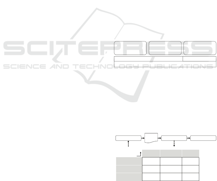
Creation and interpretation of the proposed
product representation result in a deep understanding
of the discussed product by raising awareness of
interrelations between the considered domains. In
CAE this understanding supports to define the
modelling purpose properly. Additionally extensive
collection of specifications enriches preprocessing of
the simulation model (see Fig. 2).
functional
modeling
component
structure
system
behavior
functional
modeling
DSM
relates to
DMM
implemented by
DMM
refers to
component
structure
DSM
connects
DMM
realizes
system
behavior
DSM
influences
preprocessing validation experimentation
model
Figure 2: Matrix based system representation supports
modelling.
ICINCO 2009 - 6th International Conference on Informatics in Control, Automation and Robotics
356
The matrix based system representation
identifies relevant elements within the integrated
domains and supports model conceptualization by
incorporating experience and knowledge gathered
along the product lifecycle. The product
representation finally assists validation of the
numerical simulation model applied in CAE.
According to the taxonomy of validation techniques
proposed by (Sargent 2004) the suggested approach
furthers historical data evaluation, whereas the data
proofs is the model behaves as the system does. The
following section summarizes a case study carried
out together with an industrial partner. This
technique may be applied by the developer assisted
by the user concurrently with the development of the
model.
4 CASE STUDY
In this case study a specific linear shaping machine
tool for fabricating crankshafts is modeled. The
authors apply the matrix based product
representation to support machine system simulation
as fMBS.
Measuring operation induced oscillations at the
machine tool itself confirmed the existence of
structural oscillations. The fMBS model is to
represent the structural bending induced by mass
forces that cause lower fabrication quality by
deflecting the tool from the manufacturing part. By
representing this problem entity the simulation
provides a means to finally evaluate design concepts
of sub assemblies to reduce the structural machine
misbehavior. Based on detailed product
comprehension the main purpose of applying the
suggested approach is to carry out system analysis to
support validation of the simulation model.
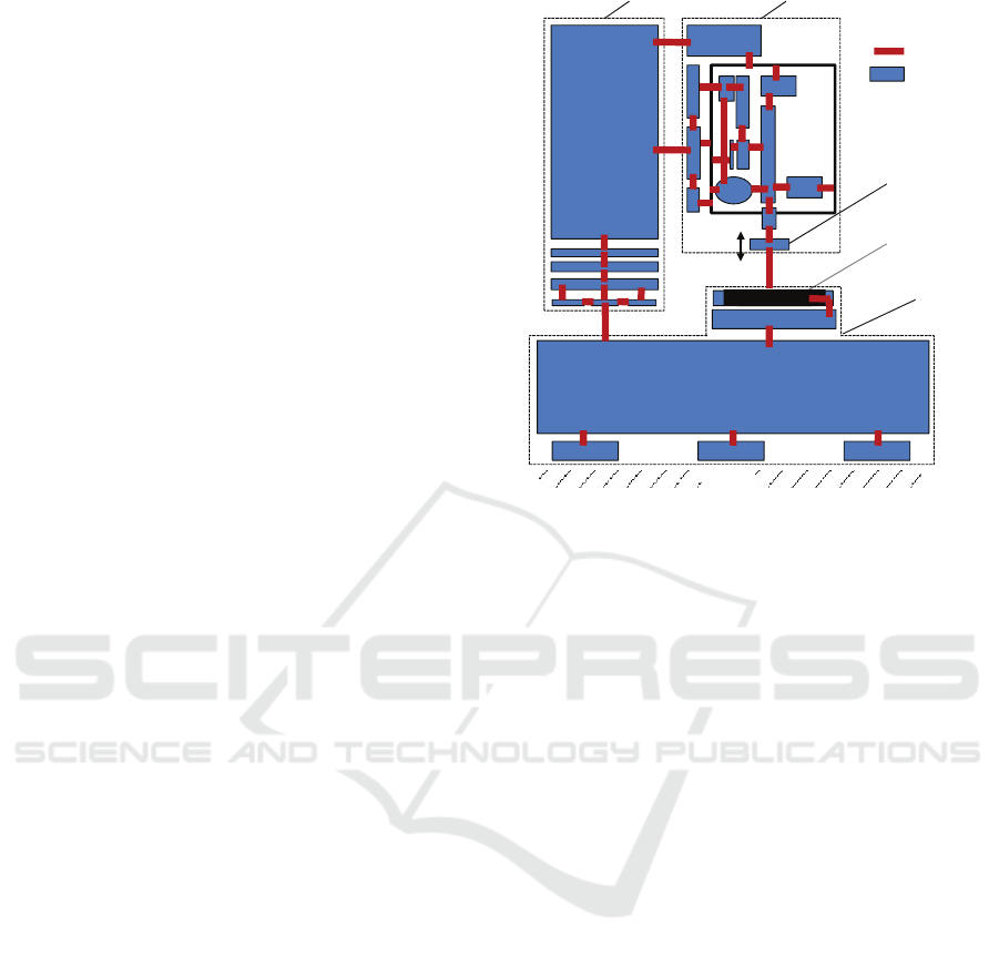
Figure 3 depicts a simplified component
structure of the shaping machine. It consists of (1)
machine bed on that the (2) machine column is
mounted. The (3) shaping head is connected to the
machine column and comprises the (4) tool that
moves highly dynamic up and down to machine the
(5) part that is fixed to the machine bed. Within the
shaping head the cutting tool moves up and down
along vertical-axis up to 700 times per minute with a
shifted weight of about 20 pounds and up to 20g.
Due to the moved mass mass-forces induce bending
of the whole machine structure that limits processing
quality.
(1) machine bed
(2) machine column (3) shaping head
(5) part
connection
components
base
(4) tool
Figure 3: Simplified component structure of the shaping
machine.
Physical components’ specification, the
assembly structure, and constraints between
components are input data for modeling. Detecting
tooth flank quality of the manufacturing part is an
indirect measure of structural bending and denotes
the machine tool behavior. Machine tool parameters
(hydraulic system pressure, lateral offset of the
column, …) as well as cutting parameters (feed,
speed, …) influence the machine behavior. Each
shaping application of particular crankshafts requires
specific cutting parameters, whereas machine
parameters are quite independent to select. fMBS is
considered a means to raise the awareness of the
actual structural bending during cutting conditions in
a new scale.
5 DISCUSSION
Figure 4 exemplifies information extracted from the
proposed matrix based product representation.
Aggregated information summarized vital aspects of
the system. It represents the domains component,
function, and behaviour. The mechanical parts are
connected by the flux of force (jack screw, machine
column, and guide rail of machine column) and are
interlinked to the functional modelling (perform
feed, vary part position) and the machine behaviour
(lateral offset of machine column). Additionally
PRODUCT REPRESENTATION TO SUPPORT VALIDATION OF SIMULATION MODELS IN COMPUTER AIDED
ENGINEERING
357
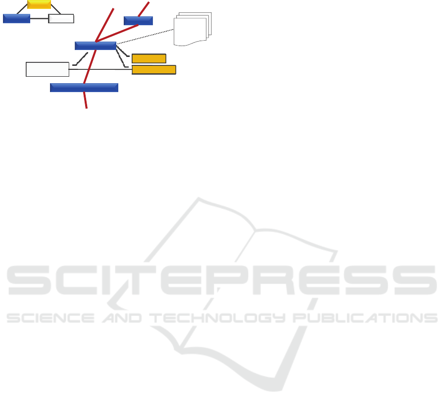
component specification such as stiffness, damping
and geometrics is attached.
lateral offset of
machine column
vary part position
perform feed
behaviorcomponet
function
stiffness
damping
geometry
machine column
guide rail of machine column
jack screw
Figure 4: Aggregated cluster of information.
This kind of data aggregation supports to set up
an enhanced fMBS simulation regarding important
modelling parameters and thus supports focusing the
modelling purpose and checking if the model’s
characteristic is as consistent to the system as
needed. The assembly shaping head is a rather
complex mechanical and functional structure and
needs to be discussed in detail regarding the
modeling purpose. Comprehension of interrelations
within this assembly is a key to become aware of the
system and thus vitally determines the preprocessing
of the fMBS. When modeling the system the
developers focus on representing the machine
complexity as far as needed, especially when
integrating machine parameters and flexible parts.
The matrix based machine tool representation
supported the determination of both the appropriated
system boundary and the level of detail in
preprocessing the fMBS. Besides it also supported
the identification of particular parameters, which
were primarily considered less important to
sufficiently represent the structural behavior of the
machine tool. The matrix based representation
provided the base for this information to become
worthy. Besides the matrix based representation also
measurements of operation induced structural
oscillations, and physical experiments supported the
validation of the fMBS. Concurrent model validation
enables to mature the fMBS simulation model
further. In order to provide a means to evaluate the
cause of tool deflection a properly validated fMBS is
needed. Currently the fMBS represents the
deflection of the tool identified by indirectly by
measuring crank shafts, but sensitivity analysis is
still been carried out. In modeling the iterative
approach is quite time consuming and it becomes
difficult to determine when the model is completely
validated. Validation of the model takes place quite
objectively by integrating the model developer and
the user systematically.
6 CONCLUSIONS
The exemplified case study has proven that the
suggested matrix based product representation could
successfully support preprocessing and validation of
a fMBS. Supported by the method specifications and
machine parameters are identified to be integrated in
the fMBS to represent structural bending induced by
moved mass. Applying the suggested approach of
matrix based product representation enables a
holistic view of the system regarding component
structure, functional modeling, and product behavior
to support both preprocessing and validation of the
simulation model. The significance of the suggested
matrix based product representation strongly
interrelates with the level of detail gained in each
domain.
The authors will detail the presented case study
further more to deeply illustrate the method and will
apply the suggested approach to different products to
enrich the application areas. Another task will be to
evaluate the transfer of the suggested matrix based
product representation to other simulation methods
in CAE.
REFERENCES
(VDA), V. d. A. e. V., Ed. (1999). Sicherung der Qualität
vor Serieneinsatz. Qualitätsmanagement in der
Automobilindustrie. Frankfurt am Main, Henrich
Druck+Medien.
Ariyo, O. O., C. M. Eckert, et al. (2006). On the use of
functions, behavior and structural relations as cues for
engineering change prediction. International Design
Conference - Design 2006. Dubrovnik, Croatia.
Bender, K., Ed. (2005). Embedded Systems -
qualitätsorientierte Entwicklung: Qualitätssicherung
bei Embedded Software. Berlin, Springer Verlag.
Biedermann, W. and U. Lindemann (2008). Cycles in the
Multiple-Domain Matrix – Interpretation and
Applications. 10th International DSM Conference,
Stockholm, Hansa.
Browning, T. R. (2001). Applying the Design Structure
Matrix to System Decomposition and Integration
Problems: A Review and New Directions. IEEE
Transactions on Engineering Management.
Lindemann, U. (2007). Methodische Entwicklung
technischer Produkte. Berlin, Spriger-Verlag.
Maurer, M. (2007). Structural Awareness in Complex
Product Design Munich, Dr. Hut.
ICINCO 2009 - 6th International Conference on Informatics in Control, Automation and Robotics
358

Musselman, K. J. (1994). Guidelines for simulation
project success. Simulation Conference Proceedings,
1994. Winter.
Pahl, G. and W. Beitz (1995). Engineering Design: A
Systematic Approach. London, Springer Verlag.
Robertson, N. and T. Perera (2002). "Automated data
collection for simulation?" Simulation Practice and
Theory 9(6-8): 349-364.
Robinson, S. and V. Bhatia (1995). Secrets of successful
simulation projects. Simulation Conference
Proceedings, 1995. Winter.
Sargent, R. G. (2004). Validation and verification of
simulation models. Simulation Conference, 2004.
Proceedings of the 2004 Winter.
Schiehlen, W. (1997). "Multibody System Dynamics:
Roots and Perspectives." Multibody System Dynamics
1(2): 149-188.
Schwertassek, R., O. Wallrapp, et al. (1999). "Flexible
Multibody Simulation and Choice of Shape
Functions." Nonlinear Dynamics 20(4): 361-380.
Shabana, A. A. (1997). "Flexible Multibody Dynamics:
Review of Past and Recent Developments." Multibody
System Dynamics 1(2): 189-222.
VDI, Ed. (2005). Classification and evaluation of
description methods in automation and control
technology, VDI/VDE 3681 Düsseldorf.
PRODUCT REPRESENTATION TO SUPPORT VALIDATION OF SIMULATION MODELS IN COMPUTER AIDED
ENGINEERING
359
