
FAR-END CROSSTALK IN ITERATIVELY DETECTED
MIMO-OFDM TWISTED PAIR TRANSMISSION SYSTEMS
Andreas Ahrens
Hochschule Wismar, University of Technology, Business and Design
Department of Electrical Engineering and Computer Science, Philipp-M¨uller-Straße 14, 23966 Wismar, Germany
Christoph Lange
T-Systems Enterprise Services GmbH, Goslarer Ufer 35, 10589 Berlin, Germany
Keywords:
Twisted-pair Cable, OFDM, Singular-Value Decomposition, Multiple Input Multiple Output System, Iterative
Decoding, EXIT Charts.
Abstract:
Crosstalk between neighbouring wire pairs in multi-pair copper cables is an important disturbance, which
essentially limits the transmission quality and the throughput of such cables. For high-rate transmission, often
the strong near-end crosstalk (NEXT) disturbance is avoided or suppressed and only the far-end crosstalk
(FEXT) remains as crosstalk influence. In this contribution the effect of far-end crosstalk (FEXT) in iteratively
detected MIMO-OFDM transmission schemes is studied. EXIT (extrinsic information transfer) charts are used
for analyzing and optimizing the convergence behaviour of the iterative demapping and decoding.
1 INTRODUCTION
The local cable network substantially ensures the
fixed subscriber access to telephone and data ser-
vices. For the most parts this fixed access network
consists of multi-pair symmetric copper cables, where
based on electromagnetic coupling, electrical energy
passes over from one wire pair to adjacent ones and
crosstalk arises, if the signals in the distinct wire
pairs lie in the same or at least in overlapping fre-
quency ranges (Valenti, 2002). Crosstalk as an elec-
tromagnetic coupling between adjacent wire pairs is
one of the most limiting disturbances in local ca-
ble networks. Thereby near-end crosstalk (NEXT)
and far-end crosstalk (FEXT) occur in bidirectional
driven cables (Valenti, 2002). Since the NEXT is a
very strong disturbance (Valenti, 2002) several tech-
niques have been developed in order to avoid or sup-
press NEXT (Honig et al., 1990). In this case only
the FEXT remains as a crosstalk influence. Often
short cables are used in high-data rate systems in fixed
access networks, e.g., optical fibre transmission is
used up to a street cabinet or a building and the last
drop is bridged by copper cables. Interestingly, in-
vestigations in (Lange and Ahrens, 2005) have shown
that the FEXT impact is much stronger in short ca-
bles than in longer ones. Considering cables or ca-
ble binders as MIMO (multiple input multiple out-
put) channels, FEXT in multi-pair copper cables can
be seen as a possible application for MIMO tech-
niques. From broadband radio transmission channels,
it is well-known that MIMO techniques are able to
overcome the limiting factor of multipath propaga-
tion known from single-carrier transmission schemes
(Raleigh and Cioffi, 1998; Raleigh and Jones, 1999).
Powerful coding algorithms are used in wireline
transmission systems. As an example it should be
mentioned, that in both voiceband modem technol-
ogy as well as in the latest VDSL2 (very-high rate
digital subscriber line) systems (ITU-T Recommen-
dation G.993.2, 2006), trellis-coded modulation is
used. Against this background, the novel contribu-
tion of this paper is that we illustrate the effect of
FEXT in iteratively detected MIMO-OFDM trans-
mission schemes, whereby both the uncoded as well
as the coded systems are restricted to support the same
user data rate within the same bandwidth. The per-
formance investigations are carried out by computer
simulations and confirmed by EXIT (extrinsic infor-
mation transfer) charts (Brink, 2001).
The remainder of this paper is organized as fol-
lows: Section 2 introduces the cable characteristics
and in 3 the FEXT impact is analyzed. In 4 the
multicarrier MIMO system model is introduced and
39
Ahrens A. and Lange C. (2008).
FAR-END CROSSTALK IN ITERATIVELY DETECTED MIMO-OFDM TWISTED PAIR TRANSMISSION SYSTEMS.
In Proceedings of the International Conference on Signal Processing and Multimedia Applications, pages 39-46
DOI: 10.5220/0001931300390046
Copyright
c
SciTePress

the performance metrics are given. The channel en-
coded MIMO system is introduced in section 5, while
the computation of the EXIT transfer function is pre-
sented in section 6. The associated performance re-
sults are presented and interpreted in Section 7. Fi-
nally, section 8 provides our concluding remarks.
2 CABLE CHARACTERISTICS
The distorting influence of the cable on the wanted
signal is modelled by the cable transfer function
G
k
( f) = e
−l
q
j
f
f
0
, (1)
where l denotes the cable length (in km) and
f
0
represents the characteristic cable frequency (in
MHz·km
2
) (Kreß and Krieghoff, 1973).
The far-end crosstalk coupling is covered by the
transfer function G
F
( f) with
|G
F
( f)|
2
= K
F
·l · f
2
, (2)
whereby K
F
is a coupling constant of the far-end
crosstalk, which depends on the cable properties such
as the type of isolation, the number of wire pairs and
the kind of combination of the wire pairs within the
binders (Valenti, 2002; Galli and Kerpez, 2002a; Galli
and Kerpez, 2002b).
If the far-end crosstalk from several neighbouring
wire pairs is considered, with increasing distance of
the disturbing wire pair from the considered pair in a
cable the impact of far-end crosstalk decreases. Con-
sidering n
F
FEXT-disturbing wire pairs, in conformity
with cable measurements, this behaviour can be mod-
elled by (Valenti, 2002)
K
F
= n
0.6
F
·K
F1
, (3)
where K
F1
is the FEXT coupling constant for one dis-
turbing wire pair. By (3) it is taken into account, that
the wire pairs, which are located farther away from
the considered wire pair contribute less to the FEXT
disturbance than the wire pairs, which are located
closer to the considered wire pair (Kalet and Shamai
(Shitz), 1990; Valenti, 2002).
3 FEXT IMPACT
Since in the copper access network on the one hand
very short copper cables are used (e. g. in fibre to
the cabinet or fibre to the building architectures) and
on the other hand also longer copper cables are ap-
plied (e.g. in rural areas) it is of interest, how the
far-end crosstalk depends on the cable length (Lange
and Ahrens, 2005). Therefore at this point the length-
dependency of the FEXT is investigated in an exem-
plary system according to Fig. 1. For simplicity of
calculations, this length dependency of the FEXT is
investigated by means of a baseband system.
u
q 1
(t)
u
q 2
(t)
G
s
(f)
G
s
(f)
u
s 1
(t)
u
s 2
(t)
G
k
(f)
G
k
(f)
G
F
(f)
u
k 1
(t)
u
k 11
(t)
u
k 21
(t)
Figure 1: Model of transmitter and cable with FEXT (ex-
ample: n = 2).
It is assumed, that each wire pair within the cable
is feeded by a system with identical mean properties
with respect to transmit filtering, pulse frequency (or
symbol rate) f
T
= 1/T
s
, the number s of signalling
levels and the mean transmit power P
s
1
. The source
signals u
q1
(t) and u
q2
(t) traverse the transmit filters
with the transfer function G
s
( f). Then the wanted
transmit signal u
s1
(t) passes the cable and causes the
signal u
k11
(t) with power P
k11
at the cable output,
whereas the FEXT signal u
k21
(t) (with power P
k21
)
originates at the cable output, after the transmit signal
u
s2
(t) in the neighbouring wire pair passed through
both, the FEXT coupling and the cable transfer func-
tion (Fig. 1). The power
P
k11
= U
2
s
T
s
s
2
−1
3
+∞
Z
−∞
|G
s
( f) ·G
k
( f)|
2
df (4)
of the wanted signal u
k11
(t) at the cable output de-
creases monotonically with rising cable length, since
with increasing cable length the lowpass effect of the
cable G
k
( f) becomes stronger and hence the area be-
low |G
s
( f)·G
k
( f)|
2
decreases. From a practical point
of view the power
P
k21
=U
2
s
T
s
s
2
−1
3
+∞
Z
−∞
|G
s
( f)·G
F
( f)·G
k
( f)|
2
df (5)
of the FEXT signal u
k21
(t) at the cable output (n
F
= 1)
is an interesting indicator for the strength of the FEXT
disturbance. In general, this FEXT power depends on
the frequency (i. e. signal bandwidth) and on the cable
length, because G
k
( f) and G
F
( f) are functions of the
frequency f and of the cable length l. Figure 2 shows
1
In this contribution a power with the dimension
(voltage)
2
(in V
2
) is used. At a real, constant resistor this
value is proportional to the physical power (in W).
SIGMAP 2008 - International Conference on Signal Processing and Multimedia Applications
40

0 0.2 0.4 0.6 0.8 1
−80
−70
−60
−50
−40
−30
f
B
= 10 MHz
f
B
= 40 MHz
f
B
= 100 MHz
l(in k m) →
10 ·lg(P
k 21
/P
s
) (indB) →
Figure 2: FEXT power P
k21
at the cable output as a function
of the cable length l (parameter: f
B
).
the mean FEXT power (5) at the cable output de-
pending on the cable length l with root-raised cosine
transmit filtering (roll-off factor r = 0.5) (Proakis,
2000) and the exemplary parameters P
s
= 1V
2
, s = 2
and K
F1
= 2.6248 ·10
−17
(Hz
2
·km)
−1
for different
bit rates f
B
= f
T
·log
2
(s). At a fixed bit rate (fixed
required bandwidth) the FEXT power P
k21
only de-
pends on the cable length l. At very small cable
lengths firstly the FEXT power increases, since the
FEXT coupling according to (2) rises with increas-
ing cable length l. A maximum in the FEXT power
arises at relatively low cable lengths (below 0.2km),
because the FEXT power according to (5) via G
F
( f)
rises with increasing l and over G
k
( f) it decreases
with increasing cable length l, i.e., there is a depen-
dency of the FEXT power (5) on the cable length
in a opposite direction. At high symbol rates the
transmit spectrum is getting broader and this causes
a higher maximum in the FEXT power compared to
lower pulse frequencies (smaller bandwidth), because
the FEXT coupling (2) rises with frequency. The ca-
ble length, at which the maximum occurs, decreases
with increasing bit rate (increasing bandwidth of the
signal), because the lowpass impact of the cable takes
already a higher effect on a shorter cable.
In order to assess the effect of far-end crosstalk
on the wanted signal not only the pure FEXT signal
power is of interest, but rather the behaviour of the
powers of the wanted signal and the FEXT signal to
each other. This behaviour may be investigated by a
signal-to-FEXT-interference ratio (SFIR)
ρ
FN
=
+∞
R
−∞
|G
s
( f) ·G
k
( f)|
2
df
+∞
R
−∞
|G
s
( f) ·G
F
( f) ·G
k
( f)|
2
df
(6)
with modified FEXT coupling constants K
F
according
0 0.2 0.4 0.6 0.8 1
10
20
30
40
50
n
F
= 1
n
F
= 9
n
F
= 49
l(in k m) →
10 ·lg(ρ
FN
) (indB) →
Figure 3: Signal-to-FEXT-interference ratio ρ
FN
as a func-
tion of the cable length l (parameter: n
F
).
to the number n
F
of disturbing wire pairs in G
F
( f)
described in (3). Figure 3 shows the SFIR ρ
FN
as a
function of the cable length at a fixed bit rate of f
B
=
100MHz (and P
s
= 1V
2
, s = 2) for different numbers
n
F
= n−1 of disturbing wire pairs. With increasing
number n
F
of disturbers the FEXT power increases
and therefore the SFIR decreases. Since the FEXT
power (5) has a local maximum and the wanted signal
power (4) decreases monotonically with respect to the
cable length l, a minimum occurs in the SFIR function
according to (6).
In particular for short cables the FEXT impact
is very significant. Therefore especially in the case,
where short copper cables are used the exploitation of
FEXT may be useful in order to improve the trans-
mission quality.
4 MIMO-OFDM SYSTEM MODEL
Now a whole cable binder is considered as a transmis-
sion channel with multiple inputs and multiple out-
puts (MIMO). The considered cable binder consists
of n wire pairs and therefore a (n, n) MIMO transmis-
sion system arises. The mapping of the transmit sig-
nals u
sµ
(t) onto the received signals u
kµ
(t) (with µ =
1,..., n) can be described accordingly to Fig. 4. On
each wire pair of the cable binder OFDM (orthogonal
frequency division multiplexing) is used as transmis-
sion technique to combat the effects of the frequency-
selective channel (Bahai and Saltzberg, 1999; Bing-
ham, 2000). In such a (n,n)-MIMO-OFDM system,
an N-point IFFT (N subchannels) modulated data sig-
nal is transmitted on every wire pair. The system is
modelled by
u = R·c+ w . (7)
FAR-END CROSSTALK IN ITERATIVELY DETECTED MIMO-OFDM TWISTED PAIR TRANSMISSION SYSTEMS
41

u
s 1
(t)
u
s 2
(t)
u
k 1
(t)
u
k 2
(t)
G
k
(f)
G
k
(f)
G
F
(f)
G
F
(f)
Figure 4: MIMO cable transmission model system with
FEXT (n = 2).
In (7), c is the (L×1) transmitted signal vector con-
taining the L = N n complex input symbols transmit-
ted over all n wire pairs. Using OFDM with a suf-
ficient guard interval length, only symbols that are
transmitted over the same subcarrier can interfere
each other. The data vector c can be decomposed ac-
cording to
c =
c
T
1
,. ..,c
T
κ
,. ..,c
T
N
T
, (8)
where the (n ×1) vector c
κ
contains the complex in-
put symbols transmitted over the κth subcarrier on
each wire pair. Furthermore u describes the (L ×1)
received vector and w is the (L×1) vector of the Ad-
ditive, White Gaussian Noise (AWGN) having a vari-
ance of U
2
R
for both the real and imaginary parts. Ap-
plying OFDM with a sufficient guard interval length,
the matrix R in (7) gets a block diagonal structure ac-
cording to
R =
R
1
0 ··· 0
0 R
2
.
.
.
.
.
.
.
.
.
.
.
.
.
.
.
.
.
.
0 0 ··· R
N
. (9)
In equation (9) zero-matrices are denoted by 0 and
for the matrices R
κ
(with κ = 1, ... ,N) the following
syntax is used
R
κ
=
r
(κ)
11
··· r
(κ)
1n
.
.
.
.
.
.
.
.
.
r
(κ)
n1
··· r
(κ)
nn
, (10)
with the elements describing the couplings of the
data symbols on the subchannel κ. Based on the
symmetry of the considered transmission system r
(κ)
νµ
(for ν = µ) can be determined taking the FFT of
g
k
(t) = F
−1
{G
k
( f)} into account. The elements
r
(κ)
νµ
(for ν 6= µ) consider the coupling between neigh-
bouring wire pairs and can be ascertained calculat-
ing the FFT of g
kfn
(t) = F
−1
{G
F
( f) ·G
k
( f)}. The
κth value of this vector represents r
(κ)
νµ
. The ele-
ments r
(κ)
νµ
(for ν 6= µ) are assumed to be identical
for each κ, although in practical systems the cou-
pling between the wire pairs is slightly different and
it depends on their arrangement in the binder (Valenti,
2002). The subcarrier-specific interferences intro-
duced by the non-diagonal matrix R
κ
require appro-
priate signal processing strategies. A popular tech-
nique is based on the SVD of the matrix R
κ
, which
can be written as R
κ
= S
κ
·V
κ
·D
H
κ
, where S
κ
and D
H
κ
are unitary matrices and V
κ
is a real-valued diagonal
matrix of the positive square roots of the eigenvalues
of the matrix R
H
κ
R
κ
sorted in descending order
2
. Us-
ing D
κ
as preprocessing matrix at the transmitter and
S
H
κ
as postprocessing matrix at the receiver side, the
overall transmission relationship results in
y
κ
= S
H
κ
(R
κ
·D
κ
·c
κ
+ w
κ
) = V
κ
·c
κ
+ ˜w
κ
. (11)
Here, the (n×n) matrix R
κ
is transformed into n inde-
pendent, non-interfering layers having unequal gains.
Arranging the subcarrier specific received vectors y
κ
according to (8), leads to the following description of
the transmission system according to
y = V·c+ ˜w. (12)
Therein the (L × L) matrix V has a block-diagonal
structure according to
V =
V
1
0 ··· 0
0 V
2
.
.
.
.
.
.
.
.
.
.
.
.
.
.
.
.
.
.
0 0 ··· V
N
. (13)
Based on the diagonal structure of the subcarrier spe-
cific (n×n) matrices V
κ
, the channel matrix R is de-
composed into L = N n independent, non-interfering
layers having unequal gains.
In general, the quality of data transmission can be
informally assessed by using the signal-to-noise ratio
(SNR) at the detector’s input defined by the half ver-
tical eye opening and the noise power per quadrature
component according to
ρ =
(Half vertical eye opening)
2
Noise Power
=
(U
A
)
2
(U
R
)
2
, (14)
which is often used as a quality parameter (Ahrens
and Lange, 2006). The relationship between the
signal-to-noise ratio ρ = U
2
A
/U
2
R
and the bit-error
probability evaluated for AWGN channels and M-ary
2
The transpose and conjugate transpose (Hermitian) of
D
κ
are denoted by D
T
κ
and D
H
κ
, respectively.
SIGMAP 2008 - International Conference on Signal Processing and Multimedia Applications
42

Quadrature Amplitude Modulation (QAM) is given
by (Kalet, 1987; Proakis, 2000)
P
BER
=
2
log
2
(M)
1−
1
√
M
erfc
r
ρ
2
. (15)
When applying the proposed system structure, the
SVD-based equalization leads to different eye open-
ings per layer ℓ according to
U
(ℓ)
A
=
p
ξ
ℓ
·U
sℓ
, (16)
where U
sℓ
denotes the half-level transmit ampli-
tude assuming M
ℓ
-ary QAM and
p
ξ
ℓ
represents
the weighting factor (singular value) resulting from
the subcarrier-based equalization. Together with the
noise power per quadrature component, the SNR per
layer becomes
ρ
(ℓ)
=
U
(ℓ)
A
2
U
2
R
= ξ
ℓ
(U
sℓ
)
2
U
2
R
. (17)
The bit-error probability per layer ℓ is given by
(Ahrens and Lange, 2006)
P
(ℓ)
BER
=
2
1−
1
√
M
ℓ
log
2
(M
ℓ
)
erfc
r
ξ
ℓ
2
·
U
sℓ
U
R
!
. (18)
The resulting average bit-error probability assuming
different QAM constellation sizes results in
P
BER
=
1
∑
L
ν=1
log
2
(M
ν
)
L
∑
ℓ=1
log
2
(M
ℓ
)P
(ℓ)
BER
. (19)
Therein the number of transmitted bits per data block
results in
R =
L
∑
ℓ=1
log
2
M
ℓ
, (20)
assuming that all L layers are used for the data trans-
mission. Considering QAM constellations, the aver-
age transmit power P
sℓ
per layer ℓ may be expressed
as (Forney et al., 1984; Kalet, 1989)
P
sℓ
=
2
3
U
2
sℓ
(M
ℓ
−1) . (21)
Combining (17) and (21), the layer-specific SNR re-
sults in
ρ
(ℓ)
= ξ
ℓ
3
2(M
ℓ
−1)
P
sℓ
U
2
R
. (22)
Using a parallel transmission over N subchannels the
overall mean transmit power per wire yields to
P
s
= N ·P
sℓ
= N
2
3
U
2
sℓ
(M
ℓ
−1) , (23)
and results in a total transmit power of nP
s
by taking
n wire-pairs into account. Assuming that the transmit
i b
˜
b
c
1,k
c
2,k
c
L,k
encoder
∏
Mapper
Mapper
Mapper
˜
b
1,k
˜
b
2,k
˜
b
L,k
MUX and Buffer
Figure 5: The channel-encoded MIMO-OFDM transmitter
structure.
power is uniformly distributed over the number of ac-
tivated layers per wire, i. e., P
sℓ
= P
s
/N, the half-level
transmit amplitude U
sℓ
per layer results in
U
sℓ
=
s
3P
s
2N(M
ℓ
−1)
. (24)
The signal-to-noise ratio per layer ℓ, defined in (17),
results together with (24) in
ρ
(ℓ)
= ξ
ℓ
3
2N(M
ℓ
−1)
P
s
U
2
R
. (25)
5 CODED MIMO-OFDM SYSTEM
The transmitter structure including channel coding is
depicted in Fig. 5. The encoder employs a rate 1/4
non-recursive, non-systematic convolutional (NSC)
code using the generator polynomials(7,7,7,5) in oc-
tal notation. The uncoded information is organized
in blocks of N
i
bits, consisting of at least 1000 bits,
depending on the specific QAM constellation used.
Each data block i is encoded and results in the block
b consisting of N
b
= 2N
i
+ 8 encoded bits, includ-
ing 2 termination bits. The encoded bits are inter-
leaved using a random interleaver and stored in the
vector
˜
b. The encoded and interleaved bits are then
mapped onto the layers. The task of the multiplexer
and buffer block of Fig. 5 is to divide the vector of
encoded and interleaved information bits
˜
b into sub-
vectors (
˜
b
1,k
,
˜
b
2,k
,··· ,
˜
b
L,k
), each consisting of R bits
according to the chosen throughput. The individual
binary data vectors
˜
b
ℓ,k
are then mapped to the QAM
symbols c
ℓ,k
according to the specific mapper used.
The iterative demodulatorstructure is shown in Fig. 6.
When using the iteration index ν, the first iteration of
ν = 1 commences with the soft-demapper delivering
the N
b
log-likelihood ratios (LLRs) L
(ν=1)
2
(
˜
b) of the
encoded and interleaved information bits, whose de-
interleaved version L
(ν=1)
a,1
(b) represents the input of
the convolutional decoder as depicted in Fig. 6. This
channel decoder provides the estimates of the origi-
nal uncoded information bits, i. e. L
(ν=1)
1
(i), as well
FAR-END CROSSTALK IN ITERATIVELY DETECTED MIMO-OFDM TWISTED PAIR TRANSMISSION SYSTEMS
43

y
1,k
y
2,k
y
L,k
Soft Demapper
L
(ν)
2
(
˜
b)
∏
−1
∏
L
(ν)
a,1
(b)
decoder
L
(ν)
1
(i)
L
(ν)
1
(b)
L
(ν−1)
e,1
(b)
L
(ν)
a,2
(
˜
b)
Figure 6: Iterative demodulator structure.
as the LLRs of the N
b
NSC-encoded bits in the form
of
L
(ν=1)
1
(b) = L
(ν=1)
a,1
(b) + L
(ν=1)
e,1
(b) . (26)
As seen in Fig. 6 and Eq. (26), the LLRs of the
NSC-encoded bits consist of the receiver’s input sig-
nal itself plus the extrinsic information L
(ν=1)
e,1
(b),
which is generated by subtracting L
(ν=1)
a,1
(b) from
L
(ν=1)
1
(b). The appropriately ordered, i. e. interleaved
extrinsic LLRs are fed back as a priori information
L
(ν=2)
a,2
(
˜
b) to the soft demapper of Fig. 6 for the sec-
ond iteration. The N
b
LLRs L
(ν)
2
(
˜
b) are composed of
the subvectors (L
(ν)
2
(
˜
b
1,k
),L
(ν)
2
(
˜
b
2,k
),··· , L
(ν)
2
(
˜
b
L,k
)),
each consisting of R elements according to the cho-
sen throughput. Each vector L
(ν)
2
(
˜
b
ℓ,k
) is generated
by the soft demapper from the MIMO channel’s out-
put y
ℓ,k
and the a-priori information L
(ν)
a,2
(
˜
b
ℓ,k
) pro-
vided by the channel decoder. After the first iteration,
this a-priori information emerges from the N
b
LLRs
L
(ν)
a,2
(
˜
b), which are again decomposed into the subvec-
tors (L
(ν)
a,2
(
˜
b
1,k
),L
(ν)
a,2
(
˜
b
2,k
),··· ,L
(ν)
a,2
(
˜
b
L,k
)), each con-
sisting of R elements.
6 EXIT CHART
The transmitted data sequence B is multiplexed onto
the different used layers ℓ and results in the layer spe-
cific sequence
3
B
ℓ
with ℓ = 1, 2, ...,L. The stationary
binary input sequence B
ℓ
= [B
ℓ,1
,B
ℓ,2
,. ..,B
ℓ,k
,. ..]
consists of r.v.s B
ℓ,k
, where the corresponding real-
izations b
ℓ,k
have an index length of 1 bit and are
taken from a finite alphabet B = {0,1} The map-
per output sequence C
ℓ
= [C
ℓ,1
,C
ℓ,2
,. ..,C
ℓ,k
,. ..] on
the ℓ-th layer consists of r.v.s C
ℓ,k
, where the cor-
responding realizations c
ℓ,k
have an index length of
3
Random variables (r.v.s) are denoted with capital letters
and their corresponding realizations with lower case letters.
Sequences of random variables and realizations are indi-
cated by boldface italics letters (as B or b ). Furthermore,
boldface roman letters denote vectors (as B or b). The time
instant is denoted with k and the layer with ℓ.
log
2
(M
ℓ
) bits and are taken from a finite alphabet
C = {0, 1,.. .,M
ℓ
−1}. The symbols c
ℓ,k
are trans-
mitted over independent channels resulting in the re-
ceived values y
ℓ,k
. The resulting layer-specific model
is shown in Fig. 7. The a priori channel models the
a priori information used at the soft demapper. The
sequence A
ℓ
= [A
ℓ,1
,A
ℓ,2
,. ..,A
ℓ,k
,. ..] with the cor-
responding realizations a
ℓ,k
contains the a priori LLR
information passed to the demapper.
b
ℓ,k
c
ℓ,k
y
ℓ,k
a
ℓ,k
e
ℓ,k
Mapper
Comm.
channel
A Priori
channel
Soft Demapper
Figure 7: Transmission model analyzing the ℓ-th layer.
EXIT charts visualize the input/ output character-
istics of the soft demapper and the decoder in terms
of a mutual information transfer between the data se-
quence B
ℓ
and the sequence A
ℓ
of the a priori LLR
information at the input of the soft demapper, as well
as between B
ℓ
and the sequence E
ℓ
of the extrinsic
LLR at the output, respectively. Denoting the mu-
tual information between two r.v.s X and Y as I(X;Y)
we may define for a given sequence B
ℓ
the quantities
I
ℓ,A
= I(A
ℓ
;B
ℓ
) as well as I
ℓ,E
= I(E
ℓ
;B
ℓ
). Herein,
I
ℓ,A
represents the average a priori information and
I
ℓ,E
the average extrinsic information, respectively
(Ahrens et al., 2008). The transfer characteristic T of
the soft demapper is given by I
ℓ,E
= T(I
ℓ,A
,ρ), where
ρ represents the SNR of the communication channel.
Analyzing the outer decoder in a serially concatenated
scheme T does not depend on ρ. An EXIT chart is
now obtained by plotting the transfer characteristics T
for both the demapper and the decoder within a single
diagram, where the axes have to be swapped for one
of the constituent decoders (Brink, 2001) (normally
the outer one for serial concatenation).
Transmitting R bits per data block, a layer specific
parameter α
(ℓ)
can be defined as follows
α
(ℓ)
=
log
2
M
ℓ
R
, (27)
describing the fraction of the data sequence B that is
transmitted over the ℓth layer, i. e. B
ℓ
. The mutual
information for a given sequence B and the extrinsic
LLR E at the output is obtained by
I(E ;B ) =
L
∑
ℓ=1
α
(ℓ)
I(E
ℓ
;B
ℓ
) , (28)
as it was shown in (Ahrens et al., 2008). Hence, the
mutual information for a given sequence B and the
SIGMAP 2008 - International Conference on Signal Processing and Multimedia Applications
44
extrinsic LLR E is effected by the layer-specific char-
acteristics, i.e. the SNR and the mapping of the bits
to both the QAM symbols as well as to the layers, as
well as the layer specific parameters α
(ℓ)
.
7 RESULTS
The FEXT impact is in particular strong for short ca-
bles (Valenti, 2002). Therefore for numerical analysis
an exemplary cable of length l = 0.4km with n = 10
wire pairs is chosen. The wire diameter is 0.6mm
and hence a characteristic cable frequency of f
0
=
0.178MHz·km
2
is assumed. On each of the wire
pairs a multicarrier system with N = 10 subcarriers
was considered. The actual crosstalk circumstances
are difficult to acquire and they vary from cable to ca-
ble. Therefore an exemplary mean FEXT coupling
constants of K
F
= 10
−13
.. . 10
−15
(Hz
2
· km)
−1
are
employed (Valenti, 2002; Aslanis and Cioffi, 1992).
The average transmit power on each wire pair is sup-
posed to be P
s
= 1V
2
and as an external disturbance
a white Gaussian noise with power spectral density
Ψ
0
is assumed. Identical systems on all wire pairs are
presumed (multicarrier symbol duration T
s
= 2µs, M-
ary QAM and a guard interval length of T
g
= T
s
/2).
Furthermore, the baseband channel of the multicarrier
system is excluded from the transmission in order to
provide this frequency range for analogue telephone
transmission. For a fair comparison the ratio of sym-
bol energy to noise power spectral density at the cable
output is defined for the MIMO case (n > 1) accord-
ing to
E
s
Ψ
0
=
T
s
+ T
g
P
k
+ (n−1)P
kfn
Ψ
0
, (29)
with P
k
as mean power of the signal on the direct
paths at the cable output and P
kfn
as mean FEXT
signal power at the cable output (Ahrens and Lange,
2006). Using the constraint-length K = 3 NSC code
with the generator polynomials of (7,7,7,5) in oc-
tal notation, the performance is analyzed for an effec-
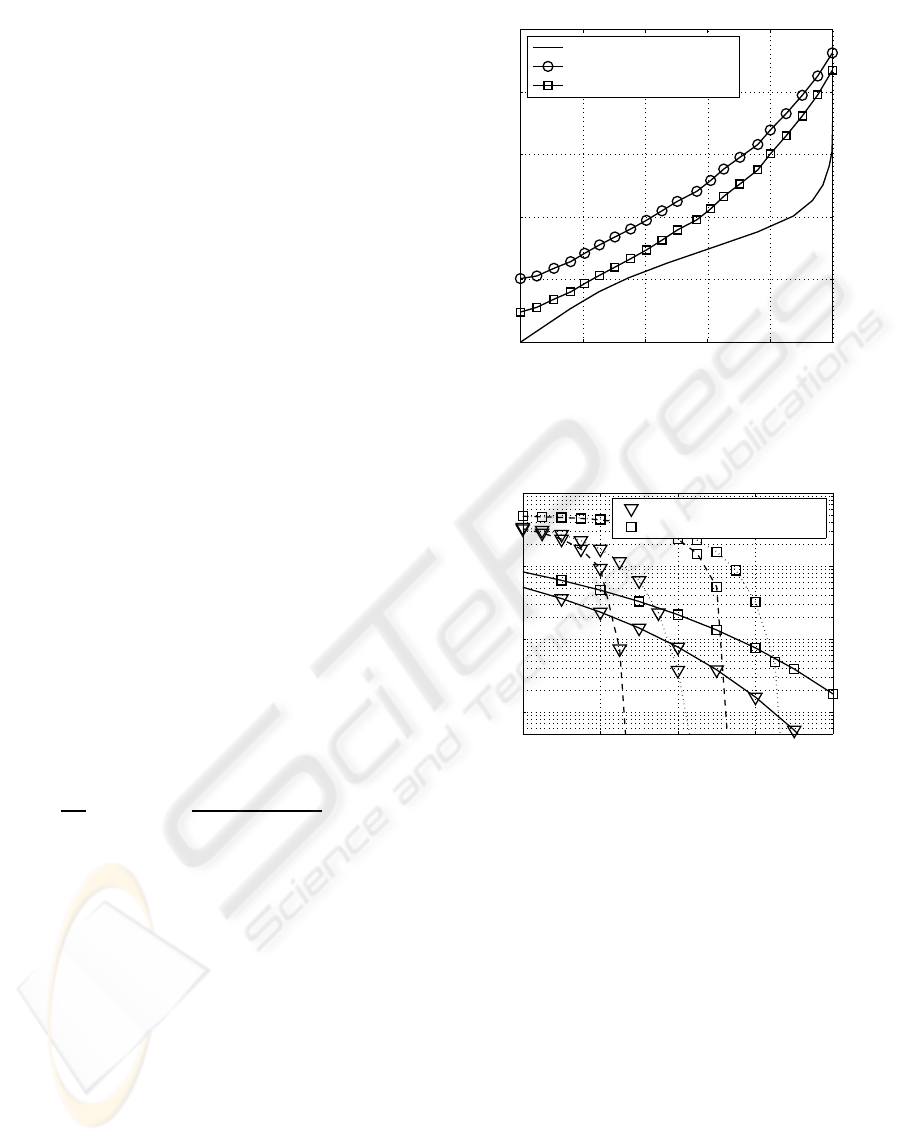
tive user throughput of 4 bit/s/Hz. Our results, ob-
tained by analyzing the soft-demapper characteristic
(Fig. 8), suggest that the performance of the MIMO-
OFDM system is strongly effected by the FEXT cou-
pling. Here it turns out that a heavy FEXT coupling
is highly beneficial for a fast convergence in the low
SNR region as it is can be seen in Fig. 9. In general,
the achievable performance of the iterative decoder is
substantially affected by the specific mapping of the
bits to both the QAM symbols as well as to the layers.
While the employment of the classic Gray-mapping
is appropriate in the absence of a priori information,
0 0.2 0.4 0.6 0.8 1
0
0.2
0.4
0.6
0.8
1
extrinsic demapper output →
extrinsic decoder output →
NSC code with K = 3
K
F
= 10
−13
(Hz
2
·km)
−1
K
F
= 10
−15
(Hz
2
·km)
−1
Figure 8: Exit chart with anti-Gray mapping on all activated
layers at 10 log
10
(E
s
/Ψ
0
) = 15 dB.
12 14 16 18 20
10
−3
10
−2
10
−1
10
0
10 ·lg(E
s
/Ψ
0
) (in dB) →
bit-error rate →
K
F
= 10
−13
(Hz
2
·km)
−1
K
F
= 10
−15
(Hz
2
·km)
−1
Figure 9: BER of the investigated system (solid line , un-
coded system using 4-QAM on all layers, dotted line , iter-
atively detected coded system (3 iterations) with anti-gray
mapping and 16-QAM on all layers, dashed line , itera-
tively detected coded system (10 iterations) with anti-gray
mapping and 16-QAM on all layers).
the availability of a priori information in iteratively
detecting decoders requires an exhaustive search for
finding the best non-Gray – synonymously also re-
ferred to as anti-Gray – mapping scheme (Chindapol,
2001). Investigations in (Ahrens et al., 2008) have
shown that layer-specific mapping schemes only offer
a slightly better performance at low SNRs. Therefore
throughout this work anti-gray mapping were used on
all layers. Our BER curves obtained by computer
simulations show that the overall BER performance
is strongly effected by both the FEXT coupling and
the number of iterations. Thereby the FEXT coupling
between neighbouring wire pairs seems to be a real
catalyst for the overall performance that is effected
FAR-END CROSSTALK IN ITERATIVELY DETECTED MIMO-OFDM TWISTED PAIR TRANSMISSION SYSTEMS
45

by both the cable length as well as the cable proper-
ties such as the type of isolation, the number of wire
pairs and the kind of combination of the wire pairs
within the binders.
8 CONCLUSIONS
In this contribution the FEXT impact in iteratively de-
tected MIMO-OFDM transmission schemes has been
studied. Our results show that FEXT is not neces-
sarily a limiting factor if appropriate signal process-
ing strategies are used. Our results show that a heavy
FEXT impact is overall beneficial for a good conver-
gence behaviour at low SNR. Having hybrid optical
and electrical fixed access networks with relatively
short copper cables (e. g. fibre transmission up to
a street cabinet or a building and bridging the last
short drop by already installed twisted pair copper
cables), iteratively detected and SVD-aided MIMO-
OFDM transmission schemes seems to be a true alter-
native for delivering broadband services, when heavy
FEXT couplingsbetween neighbouringwire pairs can
be expected.
REFERENCES
Ahrens, A., K¨uhn, V., and Weber, T. (2008). Iterative De-
tection for Spatial Multiplexing with Adaptive Power
Allocation. In 7th International Conference on Source
and Channel Coding (SCC), Ulm.
Ahrens, A. and Lange, C. (2006). Optimal Power Allo-
cation in a MIMO-OFDM Twisted Pair Transmission
System with Far-End Crosstalk. In International Con-
ference on Signal Processing and Multimedia Appli-
cations (SIGMAP), Set´ubal (Portugal).
Aslanis, J. T. and Cioffi, J. M. (1992). Achievable Infor-
mation Rates on Digital Subscriber Loops: Limiting
Information Rates with Crosstalk Noise. IEEE Trans-
actions on Communications, 40(2):361–372.
Bahai, A. R. S. and Saltzberg, B. R. (1999). Multi-Carrier
Digital Communications – Theory and Applications of
OFDM. Kluwer Academic/Plenum Publishers, New
York, Boston, Dordrecht, London, Moskau.
Bingham, J. A. C. (2000). ADSL, VDSL, and Multicarrier
Modulation. Wiley, New York.
Brink, S. t. (2001). Convergence Behavior of Iteratively
Decoded Parallel Concatenated Codes. IEEE Trans-
actions on Communications, 49(10):1727–1737.
Chindapol, A. Ritcey, J. A. (2001). Design, Analysis,
and Performance Evaluation for BICM-ID withsquare
QAM Constellations in Rayleigh Fading Channels.
IEEE Journal on Selected Areas in Communications,
19(5):944–957.
Forney, G. D., Gallager, R. G., Lang, G. R., Longstaff,
F. M., and Qureshi, S. U. (1984). Efficient Modu-
lation for Band-Limited Channels. IEEE Journal on
Selected Areas in Communications, 2(5):632–647.
Galli, S. and Kerpez, K. J. (2002a). Methods of Sum-
ming Crosstalk From Mixed Sources—Part I: Theo-
retical Analysis. IEEE Transactions on Communica-
tions, 50(3):453–461.
Galli, S. and Kerpez, K. J. (2002b). Methods of Sum-
ming Crosstalk From Mixed Sources—Part II: Perfor-
mance Results. IEEE Transactions on Communica-
tions, 50(4):600–607.
Honig, M. L., Steiglitz, K., and Gopinath, B. (1990). Multi-
channel Signal Processing for Data Communications
in the Presence of Crosstalk. IEEE Transactions on
Communications, 38(4):551–558.
ITU-T Recommendation G.993.2 (2006). Very high speed
digital subscriber line transceivers 2 (VDSL2). Inter-
national Telecommunication Union, Geneva.
Kalet, I. (1987). Optimization of Linearly Equalized
QAM. IEEE Transactions on Communications,
35(11):1234–1236.
Kalet, I. (1989). The Multitone Channel. IEEE Transac-
tions on Communications, 37(2):119–124.
Kalet, I. and Shamai (Shitz), S. (1990). On the Capacity of
a Twisted-Wire Pair: Gaussian Model. IEEE Trans-
actions on Communications, 38(3):379–383.
Kreß, D. and Krieghoff, M. (1973). Elementare Ap-
proximation und Entzerrung bei der
¨
Ubertragung von
PCM-Signalen ¨uber Koaxialkabel. Nachrichtentech-
nik Elektronik, 23(6):225–227.
Lange, C. and Ahrens, A. (2005). Effect of Far-End
Crosstalk in Multi-Pair Symmetric Copper Cables.
In XXI Krajowe Sympozjum Telekomunikacji (KST),
pages 181–190, Bydgoszcz (Poland).
Proakis, J. G. (2000). Digital Communications. McGraw-
Hill, Boston.
Raleigh, G. G. and Cioffi, J. M. (1998). Spatio-Temporal
Coding for Wireless Communication. IEEE Transac-
tions on Communications, 46(3):357–366.
Raleigh, G. G. and Jones, V. K. (1999). Multivariate
Modulation and Coding for Wireless Communication.
IEEE Journal on Selected Areas in Communications,
17(5):851–866.
Valenti, C. (2002). NEXT and FEXT Models for Twisted-
Pair North American Loop Plant. IEEE Journal on
Selected Areas in Communications, 20(5):893–900.
SIGMAP 2008 - International Conference on Signal Processing and Multimedia Applications
46
