
A COOPERATIVE METHOD FOR SYSTEM DEVELOPMENT
AND MAINTENANCE USING WORKFLOW TECHNOLOGIES
J. L. Leiva, J. L. Caro
Department of Computer Science, Málaga University. 29071 Málaga, Spain
A. Guevara, M. A. Arenas
Department of Computer Science, Málaga University. 29071 Málaga, Spain
Keywords: Human-Computer Interaction, Reverse engineering, Workflow, Cooperative methodology.
Abstract: Reverse engineering has arisen as a fundamental alternative in all reengineering processes. Its objective is to
recover design specifications and workflows (WF) to construct a representation of the system with a high
degree of abstraction. This paper describes the basic aspects of the EXINUS tool, enabling the generation of
process specifications and user interfaces in an organisation or business. The main advantage is the
possibility of modelling specifications of both the organisation’s current status and new methods generated
in the system. We also propose a cooperative work system in which users participate in system
development, using the advantages of the proposed tool. This methodology provides a high degree of
reliability in the development of the new system, creating competitive advantages for the organisation by
reducing times and costs in the generation of the information system (IS).
1 INTRODUCTION
Due to the rapid evolution of computer systems, the
appearance of new platforms and the logical needs
of future workflows, many systems either become
aged or at least require maintenance to adapt them to
organisations’ needs (Champy, J., Hammer, M.,
1994).
Software maintenance is not always possible,
due to multiple difficulties, such as (Chikofsky E.
and Cross J., 1990):
• Size and storage space constraints.
• The tools with which the system was created are no
longer used.
• The changes made to the information system to adapt
or improve it have made it less consistent with current
specifications.
• Impossibility of contacting with the engineers who
developed the system.
• Having used a traditional software engineering method
based on supposedly correct specifications.
One solution for the problem is the use of
reengineering and reverse engineering techniques
(Briand, L. C., Y. Labiche and Y. Miao. , 2003),
examining and reconstructing the system in order to
guarantee satisfactory communications between the
users and the experts.
We propose involving the user in system design
and analysis, to adapt the specifications to current
requirements. This paper provides a description of
the EXINUS (Ex
traction of Information from the
Us
er) tool, the purpose of which is to support and
help both users and experts to obtain specifications
of the system’s external design and to define the
workflows or functions involved.
In section 2, we study the basic aspects of the
tools, justifying the need for the interface to be the
focal point of the description. Section 3 approaches
the language to be used to describe the interfaces
automatically obtained from the user’s interaction
with the tool. This is followed by a description of the
language used to model the workflows involved in
the interface processes. Section 5 contains an
example and, finally, section 6 contains our
conclusions and shows the present state of
130
L. Leiva J., L. Caro J., Guevara A. and A. Arenas M. (2008).
A COOPERATIVE METHOD FOR SYSTEM DEVELOPMENT AND MAINTENANCE USING WORKFLOW TECHNOLOGIES.
In Proceedings of the Tenth International Conference on Enterprise Information Systems - HCI, pages 130-135
DOI: 10.5220/0001675001300135
Copyright
c
SciTePress

development of the tool and the work to be
completed in the future.
2 BASIC ASPECTS OF THE
EXINUS TOOL
The primary objective of the EXINUS tool is to help
end users and experts to obtain appropriate
specifications with which to obtain a new system
that satisfies users’ needs. It is a cooperative tool
based on the following principles:
• Users have most information about the IS; they are
aware of its functionalities, where there is room for
improvement and what will be required in the near
future.
• Ease of use so that users become involved in the
process.
• Cooperation of users to attain a common objective,
sharing information between them.
• Obtaining specifications which can be exported to a
system development environment.
The use of reverse engineering techniques as part
of the reengineering process is fundamental for
obtaining the conceptualisation of the IS, enabling
us to obtain the system design and workflow
specifications required for a representation with a
high degree of abstraction, for a better quality IS
with more efficiency, correction, usability, etc.
(Woods, S., Carriere, S.J., Kazman, R.,1999).
Reengineering is a solution to the problem of
remodelling an application. These techniques,
however, although they obtain high quality
applications with major advantages, can generate
programs which do not fully satisfy the user’s
requirements (Leiva, JL., J.L. Caro, A. Guevara,
2006). Therefore we suggest that the user should
provide the information required to obtain the
necessary present and future interface design and
workflow specifications. The method is based on
providing the user with the simple tools required to
create an external (interfaces) and internal
(workflows) of the IS, so that users are involved in
the development of the new system.
EXINUS is based on a model enabling the
specification of workflows on several levels:
management level (use of primitives), automation
(XML language) and demosstration (temporal modal
logic) (Caro, JL., Guevara A, Aguayo A., Leiva JL.,
2004).
2.1 User Interfaces as a Descriptive
Focal Point
End users find it easy to understand and describe the
processes they run on each of the interfaces they use,
so user interfaces are a focal point of our method,
aimed at obtaining as much information as possible.
One of the characteristics of EXINUS is that it
exports the specifications obtained in a language
with a high degree of abstraction.
There are currently different types of language
for describing interfaces and processes. Their
primary objective is to provide a simple description
of the structure of the interface, with a high level of
abstraction, so that this specification can be used to
generate the final user interface.
We have conducted a study of different
languages, including AAIML, AUIML, UML,
XIML, XUL and XFORMS (Azevedo, P, Merrik, R.
Roberts, D. , 2000) and concluded that we need a
language with the following characteristics:
• It must be able to describe the interfaces and processes
involved.
• It must enable the definition of systems designed in
different environments, regardless of the platform,
programming language, etc.
• It must clearly distinguish elements from the previous
and future system. In other words, it must be capable
of defining interfaces and processes of both the
present system and the system to be constructed.
• It must be flexible enough to enable us to generate
prototypes in any programming language.
Figure 1 shows how users participate in the
design process and how the focal point of our model
(Leiva, J.L., 2003) is the interface, from which not
only do we obtain specifications of the interfaces
themselves but also of the functions that the user
performs between them.
Each user involved in the project can define and
design different interfaces, with some of them being
shared by several users, so the tool has to allow for
cooperative work (Arenas, M.A, Guevara, A., Caro,
JL., Leiva, JL., 2007), enabling one user to consult
and change other users’ forms providing he/she has
the appropriate permission to do so.
Each interface designed by the user defines a set
of processes which can be basic (pertaining to the
designed object) and grouped on different levels. In
turn, processes can belong to one or several
interfaces (Leiva, J.L., 2003).
A COOPERATIVE METHOD FOR SYSTEM DEVELOPMENT AND MAINTENANCE USING WORKFLOW
TECHNOLOGIES
131

Figure 1: User Participation in Exinus.
2.2 Basic Features of the Tool
Following is a general description of the main
features provided by the EXINUS tool, showing
how powerful it is. Its basic features include:
• Creation of engineering/reengineering projects.
• Creation of work teams, grouped on levels.
• Creation-Editing of user interfaces, defined both by the
user him/herself or by other users.
• Creation of workflows on different levels.
• Grouping of workflows from a lower level on a higher
level.
• Generation of specifications.
• Obtaining XML files for interfaces.
• Obtaining XPDL files for processes.
To restructure the system, it is essential to
compile information provided by the user, based on
the interface and process models.
Once the external appearance of the interface has
been designed, the data related to its functionality is
collected in order to obtain the required workflow
diagrams.
Besides creating forms, the tool enables the creation
of tasks aimed at grouping together the interfaces
involved in the same process. The tasks can be described
when the design of an interface is completed.
For users to describe different interfaces, they
are supplied with an easy-to-use toolbar with
different objects (text fields, labels, lists,
checkboxes, option buttons, command buttons, etc.).
The environment is attractive enough for all
users to actively participate. Each defined object will
have a series of properties, some related to their
external appearance (size, colour, position) and
others with their individual behaviour (for instance,
a given command button remains disabled until a
certain value is entered in given text fields, etc.)
Each time the user performs an operation on the
form, he/she is providing information of different
kinds. Part of this information is automatically used
by EXINUS to change styles, fonts, positions, and so
on, and the other interacts with the tool’s assistants.
In any event, the use of assistants is optional,
although advisable, for end users.
The assistant is easy to use and obtains all that is
required to define the interface’s specifications and
the basic tasks related to the defined objects.
3 LANGUAGES FOR THE
DEFINITION OF INTERFACES
AND OBJECTS
The EXINUS tool is based on a set of languages
oriented towards the representation of process and
interface requirements. We now go on to describe
the storage structure used by EXINUS. Each project
or IS is determined by a structure referencing both
the users involved in the project and the interfaces it
contains. Each interface is determined by a file
containing properties organised in a structure based
on XML, characterised by a high level of
abstraction. The following structure is used to store
project data:
Figure 2: XML structure of a project.
After the information about the users involved,
the defined interfaces are identified. When a project
is created, a structure is generating indicating the
name, the owner of the project, the users with access
to the project and the interfaces. It only stores
references to the user interfaces in the system, as
there will be an XML file with the properties of each
interface.
Figure 3: XML structure of a form.
ICEIS 2008 - International Conference on Enterprise Information Systems
132

This structure includes general information about
the interface (name, description, etc.) to
subsequently define each of the objects involved and
their attributes. The internal appearance of a form’s
description can be divided into two different parts:
part defining the properties of the interface and part
defining the components of the interface.
4 LANGUAGE FOR THE
REPRESENTATION OF
WORKFLOWS
Once the external appearance and intrinsic
functionalities of each of the described objects has
been defined, the tool has to obtain information
about workflows in order to define their
specifications. It has to distinguish between the workflows
in the present IS and the changed or new workflows
in the new system (Leiva, Caro, Guevara, 2006). The user
can define two types of task: performed on several
interfaces or performed on a single interface.
Figure 4: Task architecture of EXINUS.
The core of the tool is the definition of tasks in
‘bottom-up’ mode, based on basic or intrinsic tasks
of the form’s objects, which are grouped in others on
a higher level. For each form designed, the tool
shows the set of primitive tasks related to the objects
used in the design. The end user this groups tasks
into others on a higher level (Figure 4) and so on.
The following figures show the primitives
(Leiva, JL. Caro, JL. Guevara A., 2006)
which will
form part of the workflow diagrams obtained with
the tool:
Figure 5: Workflows description primitives.
Following are the characteristics of each of the
primitives which will form part of the workflow
diagrams generated with EXINUS:
• Workflow component: each workflow represents a
sub-task which forms part of the workflow. The flows
represented with dotted lines (c and d) show that this
flow is not in the present system but required in the
future; double line flows (b and d) show that the task
is primitive and not divided into more sub-tasks,
whereas single line workflows (a and b) can be broken
down. Continuous line flows (a and b) are current
workflows.
• Interface transition: this component is used to indicate
the changeover from one interface to another. In the
transition, there may be a parameter step, either input
(E), output (S) or both (E/S).
• Object: representation of each of the objects forming
part of the interface. The description mat involve a list
of preconditions and/or post-conditions which must be
met before and/or after the appearance of said object
on the interface
• Workflows of an object: represented in the same way
as the previous workflows, except that we use an
ellipse instead of a box.
• Start and end: start and end of the workflow.
• Alternation and junction of workflows: these
components indicate the possibility of running several
workflows simultaneously. A basic workflow is
divided into several sub-flows, of which one or
several may be run.
• Division and junction of workflows: these constructors
refer to the parallel running of workflows, creating
new sub-flows of undetermined duration which will at
some time become synchronised by the junction
constructor.
• Optional status of workflows: this component runs one
of the flows, depending on the result of predicate P.
• Repetition block: set of workflows which will be
repeated as long as condition P is met.
A COOPERATIVE METHOD FOR SYSTEM DEVELOPMENT AND MAINTENANCE USING WORKFLOW
TECHNOLOGIES
133
An XML structure is defined for each workflow, to
store a lot of properties as type, name, mode, description,
objective, clients, describers, interfaces, resources, code, …
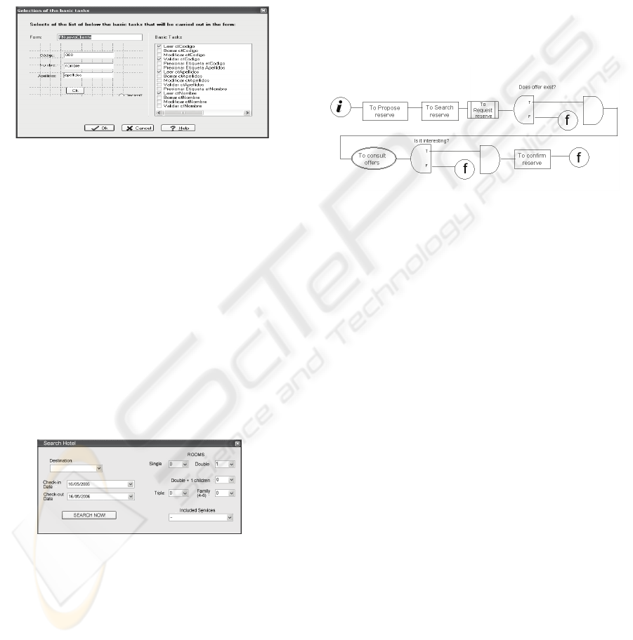
As we mentioned earlier, in the definition of the
interface the system creates tasks automatically, so
in EXINUS, when the user is going to define a
workflow, the existing tasks must be taken into
account. Figure 6 shows how the user can select the
tasks forming part of another task on a higher level
from a list of basic tasks.
Figure 6: Basic task selection interface.
5 ANALYSIS OF A FORM USING
THE EXINUS TOOL
This section includes an example showing how, with
the help of the user, the flow diagram can be
obtained with the proposed method.
The example shows how a system user performs
a search to book a hotel in a given city. Using a
simple interface creation assistant and a set of tools,
the user involved in the system maintenance process
designs the forms he or she regularly uses in the
present system, changing its characteristics and
creating forms for the future system. In this practical
case, the user designs the form shown in figure 7:
Figure 7: Form designed in EXINUS for hotel booking in
a central reservation system.
While the user creates the form, the EXINUS
tool creates interface definition structures. For each
object that the user defined on the form, external
characteristics and inherent primitive tasks can be
defined. Also, each created object has a very
important attribute determining whether the object:
• Is present in the current system and will remain in the
future system.
• Is present in the current system and will not be found
in the future system.
• Is not in the current system but will be included in the
future system.
• Is not in the current system, but will be included in the
future system replacing other objects from the current
system.
Once the form has been designed, it has to be
associated to processes. The principal workflow in
our example is Hotel Booking process. The
workflow is triggered manually by the user upon
receipt of a customer’s request for a hotel booking or
by another event such as an e-mail message from the
customer, requesting information.
Figure 8: Hotel Booking workflow.
The above diagram shows how the end user
proceeds to make a hotel booking:
• Propose type of booking: he/she indicates the type of
room, type of accommodation, arrival and departure
date.
• He/she searches for hotels satisfying the requirements
entered in the previous task.
• The user sees a new interface with a list of hotels
meeting the desired requirements. The end user
decides to close the process if there is nothing
available or make a query if there are several
possibilities, to find which is the best.
• If there is nothing suitable available, he will end the
process, but if there is, he/she will perform the task of
confirming the reservation (it is important to observe
the type of primitive used, as this task is not primitive
and will also be broken down into other sub-tasks),
thus completing the HOTEL BOOKING process.
Figures 9 show how the tool generates this type
of diagram, together with complete specifications of
both the forms and the workflows, this showing
information about tasks on different levels: from the
highest to the primitive (primitive tasks) level.
ICEIS 2008 - International Conference on Enterprise Information Systems
134
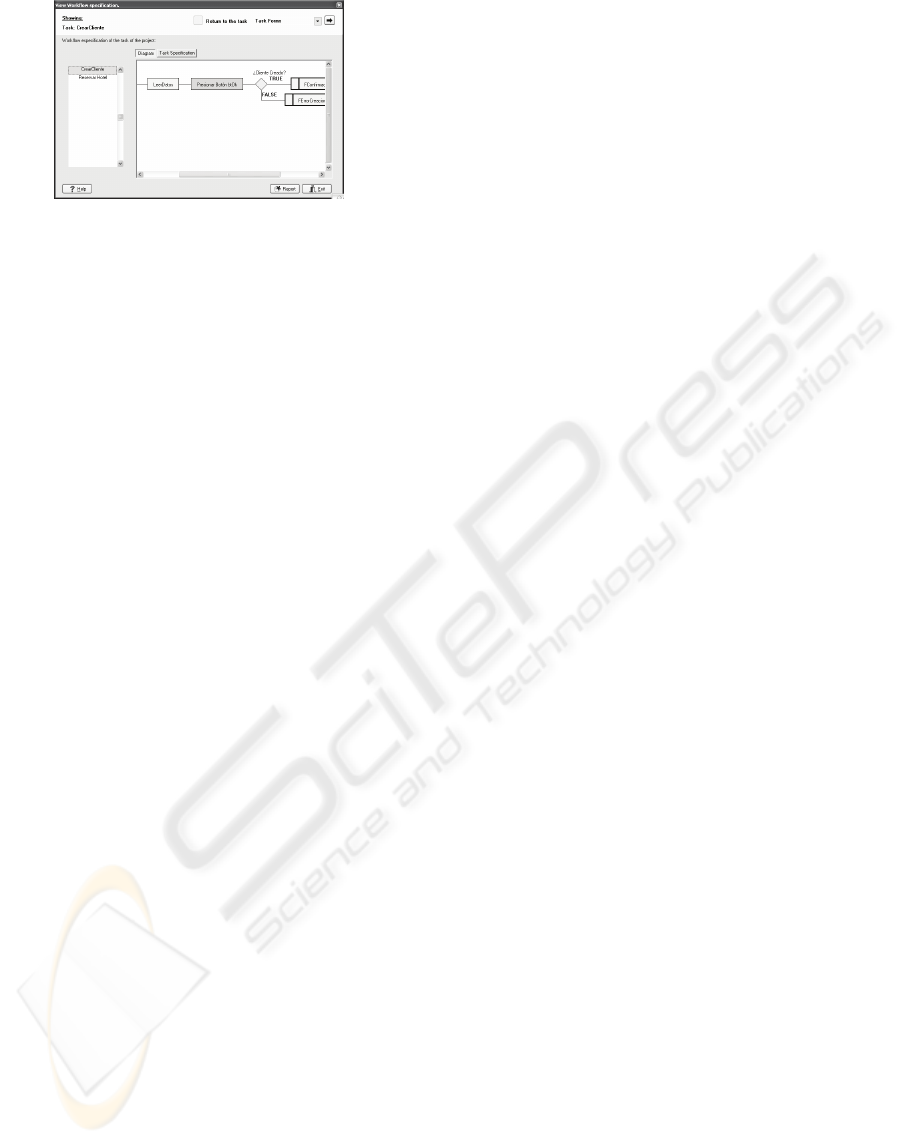
Figure 9: Workflow specification generated.
The specifications can be divided into several levels:
• General information about the project
• Information about the users and forms involved and
the tasks performed in the system.
• Information about each interface and its components.
• Information about the highest level workflows.
6 CONCLUSIONS
This paper presents a method for cooperative
software maintenance enabling the use of the
knowledge of system users, who can clearly and
precisely identify aspects which can be improved
(related to the user interface and workflows) in the
information systems they operate.
The main contribution is the EXINUS tool, the
main characteristic of which is its ease-of-use and
the quality of the specifications it generates.
If the end users and experts are capable of
joining forces to automate operations with this tool,
they will attain their objectives more efficiently.
In the future, we intent to include new
functionalities in EXINUS, making task description
and management even easier, with the work process
definitions created by experts compatible with the
processed designed by users.
ACKNOWLEDGEMENTS
This work is supported by Málaga University project
‘Workflow modelling techniques to evaluate business
processes for organizations and enterprises’.
REFERENCES
Arenas, M.A., Guevara, A., Caro, J., Leiva, J. Cooperative
Metholodology for Information Systems ENC, 2007.
Azevedo, P, Merrik, R. OVID to AUIML- User Oriented
Interface Modelling IBM UK. TUPIS 2000.
Bianchi, A., Caivano, D., Marengo, V., Visaggio, G.;
Iterative Reengineering of Legacy Functions,
Proceedings IEEE International Conference on
Software Maintenance Computer, 2001.
Booch, Rumbaugh , Jacobson.. El Lenguaje Unificado de
Modelado. Addison Wesley Iberoamericana, 1999.
Briand, L. C., Y. Labiche and Y. Miao. Towards the
Reverse Engineering of UML Sequence Diagrams.
Proceedings of the 10th Working Conference in
Reverse Engineering, IEEE Computer Society, 2003
Caro, J., Guevara A, Aguayo A., Leiva J. Communication
based workflow loop formalization using Temporal
Logic of Actions (TLA). CSAC- ICEIS 2004.
Carrillo A, Falgueras J, Guevara: Tool for the Design, Specification
and Generation of Goals Driven User Interfaces. ICEIS 2006
Champy, J., Hammer, M. Reingeniería, Ed. Norma, 1994.
Chikofsky E. and Cross J., Reverse engineering and
design recovery:A taxonomy. IEEE Software, 7. 1990.
Di Lucca, G., R. Fasolino, F. Pace, P. Tramontana , U.De
Carlini WARE: a tool for the Reverse Engineering of
Web Applications. 6th European Conference on
Software Maintenance and Reengineering, Budapest,
IEEE Computer Society, 2002.
García Ochoa, J. Lenguajes XML para la definición de
interfaces de usuario. Universidad de Deusto. Grupo
DELi, 2005
Hausi A. Müller, Jens H. Jahnke, Dennis B. Smith,
Margaret-Anne D. Storey,Scott R. Tilley, Kenny
Wong: "Reverse Engineering: A Roadmap," The
Future of Software Engineering Track at the 22nd
ICSE, Limerick, Ireland, 2000.
Leiva, JL., J.L. Caro, A. Guevara (Grupo SICUMA).
Aplicación de técnicas workflow a la reingeniería de
sistemas de información. CISTI 2006.
Leiva, JL. Construcciones de especificaciones de interfaces en un
proceso de reingenieria, (Orlando-USA). CISCI 2003
Woods, S., Carriere, S.J., Kazman, R. A Semantic
Foundation for Architectural Reengineering and
Interchange, 391-398. Proceedings of the International
Conference on Software Maintenance-ICSM, 1999.
Workflow Management Coalition, WfMC. Workflow
Process Definition Interchange: XML Process
Definition Language. Version 1.0., 2002.
A COOPERATIVE METHOD FOR SYSTEM DEVELOPMENT AND MAINTENANCE USING WORKFLOW
TECHNOLOGIES
135
