
ROBOTIC WHEELCHAIR CONTROL CONSIDERING USER
COMFORT
Modeling and Experimental Evaluation
Razvan Solea and Urbano Nunes
ISR - Institute of Systems and Robotics, Department of Electrical and Computer Engineering
University of Coimbra, 3030-290, Coimbra, Portugal
Keywords:
Users comfort, sliding-mode control, human head-neck complex model, intelligent wheelchair.
Abstract:
This paper analyzes the comfort of wheelchair users when a sliding-mode trajectory-tracking controller is
used. The transmission of the horizontal (fore-and-aft) vibration to the head-neck complex (HNC) in the
seated human body may cause unacceptable discomfort and motion sickness. A double-inverted pendulum
model with two degrees of freedom is considered as a model for the HNC. The user comfort is examined not
only in the time domain (using the fourth power vibration dose value), but also in the frequency domain (using
the cross-spectral density method). For measuring the acceleration of the wheelchair, along the trajectory, an
inertial measurement unit was used.
1 INTRODUCTION
Few studies have been performed addressing how dy-
namic acceleration affects wheelchair’s users. A bar-
rier to performing in-depth analysis during the pro-
cesses of wheelchair design and ride comfort is a lack
of wheelchair-acceleration data, measured over time,
that vary with the activity of the wheelchair user. Fur-
thermore, little is known about how this dynamic ac-
celeration affects user comfort. Most current litera-
ture focus on the vibration exposure of a seated oc-
cupant. To this end, standards have been developed
by the International Organization for Standardization
(ISO) to quantify how much exposure is allowable for
various frequencies of exposure. To standardize the
methods of data collection for whole-body vibration,
the ISO introduced the ISO-2631 (ISO-2631, 1997).
The boundaries in ISO-2631 are based on cumulative
root-mean-square (rms) amplitude over a single day,
specified for frequencies between 1 and 80 Hz.
The human body is a complex dynamic system,
the properties of which vary from moment to moment
and from one individual to another. From the results
of large amount of experimental data, various biome-
chanical models have been developed to describe the
human motion. These models can be grouped as
lumped or distributed parameter models. The lumped
parameter models consider the human body as sev-
eral rigid bodies, springs and dampers (Atapourfard
et al., 2002), (Atapourfard et al., 2004), (Gurses et al.,
2005). Some distributed models treat the spine as a
layered structure of rigid elements, representing the
vertebral bodies and deformable elements represent-
ing the intervertebral disc by the finite elements (Ki-
tazaki and Griffin, 1997).
The dynamic response of seated subjects exposed
to vibration has been widely assessed in terms of the
driving point impedance, apparent mass and transmis-
sibility (transmission of motion through the human
body). The transmission of the acceleration to the
head-neck complex (HNC) in the seated human body
may be the cause of discomfort and motion sickness
in wheelchairs. The seat back, by limiting the hor-
izontal and rotational motion of the trunk, increases
the transmission of the trunk horizontal acceleration
to the HNC. This may has considerable influence on
discomfort.
The present study focuses specifically on the in-
fluence of sliding-mode trajectory-tracking (SM-TT)
controller action on user comfort. The user com-
fort is examined not only in the time domain (using
the transmissibility parameter), but also in the fre-
quency domain. For measuring accelerations of the
wheelchair, a three-dimensional inertial sensor was
used. The analysis of user comfort is made in three
different situations: i) SM-TT controlunder odometry
navigation; ii) when the odometric data is fused with
absolute position data from magnetic markers (using
37
Solea R. and Nunes U. (2008).
ROBOTIC WHEELCHAIR CONTROL CONSIDERING USER COMFORT - Modeling and Experimental Evaluation.
In Proceedings of the Fifth International Conference on Informatics in Control, Automation and Robotics - RA, pages 37-44
DOI: 10.5220/0001487100370044
Copyright
c
SciTePress

an EKF-based fusion in the on-line pose estimation);
iii) SM-TT control with purposely-incorrectly-tuned
parameters.
2 CONTROL OF WHEELED
MOBILE ROBOTS
The application of sliding mode control strategies in
nonlinear systems has received considerable attention
in recent years (Yang and Kim, 1999), (Chwa, 2004),
(Chwa et al., 2006), (Solea and Nunes, 2007). A
well-studied example of a non-holonomic system is
a wheeled mobile robot (WMR) that is subject to the
rolling without slipping constraint.
In trajectory-tracking, is an objective to control
the non-holonomic WMR to follow a desired path,
with a given orientation relatively to the path tan-
gent, even when disturbances exist. In the case of
trajectory-tracking the path is to be followed under
time constraints. The path has an associated velocity
profile, with each point of the trajectory embedding
spatiotemporal information that is to be satisfied by
the WMR along the path. By other words, path track-
ing is formulated as having the WMR following a vir-
tual target WMR which is assumed to move exactly
along the path with specified velocity profile.
2.1 Kinematic Model of a Unicycle-type
Mobile Robot
Let the pose of the mobile robot be defined by the
vector q
r
= [x
r
,y
r
,θ
r
]
T
, where [x
r
,y
r
]
T
denotes the
robot position on the plane and θ
r
the heading angle
with respect to the x-axis. In addition, v
r
denotes the
translational velocity of the robot, and ω
r
the angu-
lar velocity around the vertical axis. For a unicycle
WMR rolling on a horizontal plane without slipping,
the kinematic model can be expressed by:
˙x
r
˙y
r
˙
θ
r
=
cosθ
r
0
sinθ
r
0
0 1
·
v
r
ω
r
(1)
which represents a non-linear system.
Controllability of the system (1) is easily checked
using the Lie algebra rank condition for nonlinear sys-
tems. However, the Taylor linearization of the system
about the origin is not controllable, thus excluding the
application of classical linear design approaches.
2.2 Trajectory Tracking Model
Without loss of generality, it can be assumed that
the desired trajectory q
d
(t) = [x
d
(t),y
d
(t),θ
d
(t)]
T
is
Table 1: ISO 2631-1 Standard.
Overall Acceleration Consequence
a
w
< 0.315m/s
2
not uncomfortable
0.315 < a
w
< 0.63m/s
2
a little uncomfortable
0.5 < a
w
< 1m/s
2
fairly uncomfortable
0.8 < a
w
< 1.6m/s
2
uncomfortable
1.25 < a
w
< 2.5m/s
2
very uncomfortable
a
w
> 2.5m/s
2
extremely
uncomfortable
generated by a virtual unicycle mobile robot. The
kinematic relationship between the virtual configura-
tion q
d
and the corresponding reference velocity in-
puts [v
d
,ω
d
]
T
is similar to (1). From the error vector
(Solea and Nunes, 2007),
x
e
y
e
θ
e
=
cosθ
d
sinθ
d
0
−sinθ
d
cosθ
d
0
0 0 1
·
x
r
− x
d
y
r
− y
d
θ
r
− θ
d
(2)
we get the error dynamics:
˙x
e
= −v
d
+ v
r
· cosθ
e
+ ω
d
· y
e
˙y
e
= v
r
· sinθ
e
− ω
d
· x
e
˙
θ
e
= ω
r
− ω
d
(3)
2.3 Trajectory Planner
A trajectory planner for human-transport robots must
generate smooth velocity profiles (linear and angu-
lar) with low associated accelerations. The trajec-
tory planning process can be divided into two sepa-
rate parts. First, a continuous collision-free path is
generated. In a second step, called trajectory gener-
ation, a velocity profile along the path is determined.
A method to generate a velocity profile, respecting
human body comfort, for any two-dimensional path
in static environments was proposed in (Solea and
Nunes, 2007).
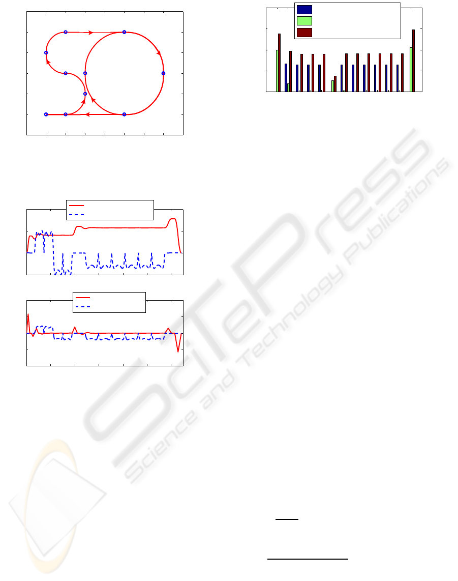
Figures 1 - 3 show an example of a planned trajec-
tory using the method described in (Solea and Nunes,
2007) were the goal was to obtain an overall rms ac-
celeration in the range of ”not uncomfortable” (see
Table 1). The overall rms acceleration is defined as:
a
w
=
q
k
2
x
· a
2
wx
+ k
2
y
· a
2
wy
+ k
2
z
· a
2
wz
(4)
where a
wx
, a
wy
, a
wz
, are the rms accelerations along
x, y, z axes respectively, and k
x
, k
y
, k
z
, are multiply-
ing factors. For a seated person k
x
= k
y
= 1.4, k
z
= 1.
For motion on the x-y plane, a
wz
= 0. The local co-
ordinate system is chosen so that the x-axis is the lon-
gitudinal trajectory direction, and y-axis is the lateral
trajectory direction.
ICINCO 2008 - International Conference on Informatics in Control, Automation and Robotics
38
−1 0 1 2 3 4 5 6 7
−1
0
1
2
3
4
5
Path
x [m]
y [m]
J(2,2,π/2)
B(1,0,0)
C(2,1,π/2)
D(1,2,π)
E(0,3,π/2)
F(1,4,0)
G(4,4,0)
K(4,4,0)
H(6,2,−π/2)
L(6,2,−π/2)
I(4,0,−π)
M(4,0,−π)
A(0,0,0)
N(0,0,−π)
Figure 1: Path example composed by thirteen path segments
calculated by the trajectory planner, from the fourteen way-
points A to N.
0 10 20 30 40 50 60
−0.5
0
0.5
1
time [s]
Velocity
Linear velocity [m/s]
Angular velocity [rad/s]
0 10 20 30 40 50 60
−1
−0.5
0
0.5
1
time [s]
Acceleration [m/s
2
]
Longitudinal accel.
Lateral accel.
Figure 2: Velocity and acceleration profiles for path de-
picted in Fig. 1.
The ISO 2631-1 standard (ISO-2631, 1997) (Ta-
ble 1) relates comfort with the overall rms accelera-
tion, acting on the human body.
Figure 1 shows the generated path, where the
larger circles represent the used fourteen waypoints
(A, B, ..., N). Each waypoint is defined by a position,
in meters, and an orientation, in radians. The gener-
ated velocity and acceleration profiles are shown in
Fig. 2. As can be observed in Fig.3, the rms overall
accelerations, in each path segment, are below the im-
posed acceleration constraint of a
w(i,i+1)
< 0.31m/s
2
.
2.4 Sliding-mode Controller
The objective of SMC is the same as for classical
controllers, i.e., force the output states to follow the
desired input states. However, the SMC is a model-
based control strategy in which the controller struc-
AB BC CD DE EF FG GH HI IJ JK KL LM MN
0
0.1
0.2
0.3
0.4
Lateral r.m.s. accel. − a
wy
Longitudinal r.m.s. accel. − a
wx
Overal r.m.s. accel. − a
w
Figure 3: Acceleration rms values for each path segment
(AB, BC, ..., MN) of path depicted in Fig. 1.
ture and gains are designed based on the system
model.
Uncertainties which exist in real mobile robot ap-
plications degrade the control performance signifi-
cantly, and accordingly, need to be compensated. In
(Solea et al., 2006) a SM-TT controller for WMRs is
proposed, where trajectory tracking is achieved even
in the presence of large initial pose errors and distur-
bances.
Let us define the sliding surface s = [s
1
s
2
]
T
as
s
1
= ˙x
e
+ k
1
· x
e
,
s
2
= ˙y
e
+ k
2
· y
e
+ k
0
· sgn(y
e
) · θ
e
.
(5)
where k
0
, k
1
, k
2
are positive constant parameters, x
e
,
y
e
and θ
e
are the trajectory-tracking errors defined in
(3). If s
1
converges to zero, trivially x
e
converges to
zero. If s
2
converges to zero, in steady-state it be-
comes ˙y
e
= −k
2
· y
e
− k
0
· sgn(y
e
) · θ
e
. For y
e
< 0 ⇒
˙y
e
> 0 if only if k
0
< k
2
· |y
e
|/ |θ
e
|. For y
e
> 0 ⇒
˙y
e
< 0 if only if k
0
< k
2
· |y
e
|/ |θ
e
|. Finally, it can be
known from s
2
that convergence of y
e
and ˙y
e
leads
to convergence of θ
e
to zero. Using the reaching law
defined in (Gao and Hung, 1993)
˙s = −Q· s− P· sgn(s) (6)
Q = diag[q
1
,q
2
], q
i
> 0,
P = diag[p
1
, p
2
], p
i
> 0, i = 1,2
sgn(s) = [sgn(s
1
),sgn(s
2
)]
T
together with (5), and after some mathematical ma-
nipulation, we get the commands for trajectory-tra-
cking controller:
˙v
c
=
1
cosθ
e
(−q
1
s
1
− p
1
sgn(s
1
) − k
1
˙x
e
−
−y
e
˙
ω
d
− ˙y
e
ω
d
+ v
r
˙
θ
e
sinθ
e
+ ˙v
d
).
(7)
ω
c
=
1
v
r
cosθ
e
+ k
0
sgn(y
e
)
(−q
2
s
2
− p
2
sgn(s
2
)−
−k
2
˙y
e
− ˙v
r
sinθ
e
+ x
e
˙
ω
d
+ ˙x
e
ω
d
) + ω
d
.
(8)
The SM-TT architecture with a on-line robot’s
pose estimator, fusing odometry with absolute posi-
tion data, as described in (Lopes et al., 2007), is de-
picted in Fig. 4.
ROBOTIC WHEELCHAIR CONTROL CONSIDERING USER COMFORT - Modeling and Experimental Evaluation
39
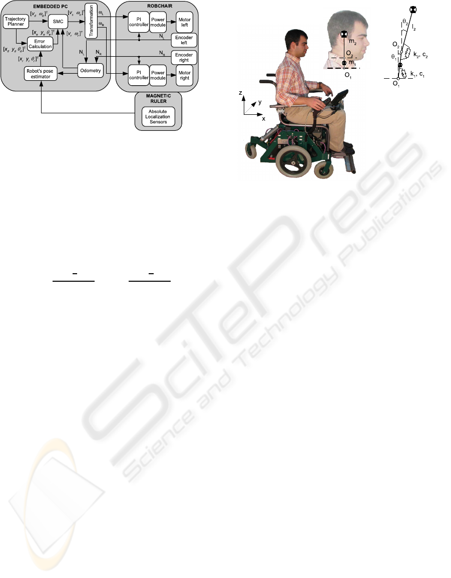
Figure 4: SM-TT control architecture with a robot’s pose
estimator, fusing odometry and absolute position data.
RobChair has a two-level control architecture (see
Fig. 4). High-level control algorithms (including ref-
erence motion generation) are written in C and run
with a sampling time of T
s
= 50 ms on a embedded
PC, which also provides a user interface with real-
time visualization and a simulation environment. The
PC communicates through a CAN bus with several
devices. Wheel velocity commands,
ω
R
=
v
c
+
L
2
· ω
c
R
, ω
L
=
v
c
−
L
2
· ω
c
R
(9)
where R is radius of the drive wheels and L the dis-
tance between drive wheels, are sent to the PI con-
trollers, and encoder measures N
R
and N
L
are received
in the robot’s pose estimator for odometric computa-
tions.
The low-level control layer is in charge of the exe-
cution of the wheels velocity control. For each wheel,
a microcontroller implements a digital PI with a cycle
time of T
c
= 5 ms. Two power amplifiers drive the
motors with PWM voltage.
3 HUMAN HEAD-NECK
COMPLEX MODEL AND
EVALUATION OF COMFORT
In general, comfort while riding depends not only on
the amplitude, but also on the frequencyof wheelchair
vibrations and accelerations. Oscillations have influ-
ence on users comfort and may affect users health.
Moreover, natural frequency of the wheelchair and
human organ is strongly related with the user’s un-
comfort while riding.
3.1 Model of Head-neck Complex
A double-invertedpendulum model with two degrees-
of-freedom is considered for the HNC model (Fig. 5).
Figure 5: Human head-neck model.
One of the centers of rotation of the model was as-
sumed to be at C7-T1 (O
1
in Fig. 5), and the other
at C0-C1 (O
2
in Fig. 5) of the cervical spine. Two
lumped masses, indicating the mass of the neck and
the mass of the head, were considered in the model.
The center of mass of the neck was assumed to be
exactly at the mid-point of the two centers of rotation.
Moreover, the center of mass of the head was assumed
to be exactly over the center of mass of the neck and
the center of rotation (Fig. 5). The equation of motion
using generalized coordinates can be expressed as:
M(q) ¨q+C(q, ˙q) ˙q+ Kq+ G(q) = Q
q
(10)
where: q =
θ
1
θ
2
, Q
q
= 0,
M(q) =
M
11
M
12
M
21
M
22
M
11
= m
1
l
2
1
+ m
2
L
2
1
+ J
1
M
12
= m
2
L
1
l
2
cos(θ
1
− θ
2
)
M
21
= m
2
L
1
l
2
cos(θ
1
− θ
2
)
M
22
= m
2
l
2
2
+ J
2
C(q, ˙q) =
c
1
+ c
2
C
12
C
21
c
2
C
12
= m
2
L
1
l
2
sin(θ
1
− θ
2
)
˙
θ
2
− c
2
,
C
21
= −m
2
L
1
l
2
sin(θ
1
− θ
2
)
˙
θ
1
− c
2
,
K =
k
1
+ k
2
−k
2
−k
2
k
2
G(q) =
−(m
2
L
1
+ m
1
l
1
) ¨xcos(θ
1
)
−m
2
l
2
¨xcos(θ
2
)
In our study, the user characteristic elements,
shown in Table 2 (from (Atapourfard et al., 2002)),
were used to model the dynamic behavior of the hu-
man HNC.
ICINCO 2008 - International Conference on Informatics in Control, Automation and Robotics
40

Table 2: Characteristics of user’s elements.
Element Neck Head
Length of segment L
i
[m] 0.080 0.138
Center of gravity l
i
[m] 0.040 0.069
Mass m
i
[kg] 1.01 4.22
Moment of Inertia J
i
[kgm
2
] 0.0011 0.210
Spring constant k
i
[Nm/rad] 14.04 10.29
Damping constant c
i
[Nms/rad] 0.347 0.230
3.2 Time-domain Calculations
The fourth power vibration dose value (VDV) is pri-
marily a measurement procedure used to report the
relative severity of complex oscillation exposures, be-
ing preferred to other measures due to its use of the
duration and variability of the motion:
VDV =
Z
T
0
[a
w
(t)]
4
· dt
1
4
(11)
in units of ms
−1.75
, where the frequency-weighted ac-
celeration is defined by a
w
(t), and T is the duration
of an experiment. VDV was selected over the differ-
ence between the peak accelerations and acceleration
rms parameter. The problem with the peak-to-peak
value is that it only represents one instance in time,
rather than the entire signal. Furthermore, the peak-
to-peak parameter does not accurately represent oscil-
latory motion. The problem with the rms value is that
it is independent of the duration of the signal, and is
designed to describe oscillatory motions.
According to the EU Directive on mechanical vi-
bration (European-Parliament and the Council of the
European Union, 2002) the average limit value of
VDV is 9.1ms
−1.75
and the upper limit is 21ms
−1.75
.
The transmissibility (T
r
) is defined as the output
VDV divided by the input VDV,
T
r
=
VDV
output
VDV
input
(12)
The transmissibility defines the performance of
the wheelchair in terms of the amplification or at-
tenuation of the vibration that is transmitted to the
occupant. A value less than unity indicates that the
accelerations were attenuated by the combination of
wheelchair and human, whereas a value great than
unity indicates an amplification of accelerations by
the wheelchair-human system.
3.3 Frequency-domain Calculations
Given the input, wheelchair acceleration, and the out-
put, acceleration obtained from the HNC model, the
transfer function is usually calculated using the cross-
spectral density (CSD) method defined as:
H
CSD
( f) =
CSD
input−output
( f)
PSD
input
( f)
(13)
where CSD
input−output
( f) is the CSD of the input and
output, and PSD
input
( f) is the power spectral density
(PSD) of the input. The advantage of using the CSD
method is that the function generates the phase of the
response and also only includes data at the input and
output that are correlated, thus reducing the effects of
noise in the measurement system.
4 EXPERIMENTAL RESULTS
In order to validate the applicability of the sliding-
mode controller for trajectory-tracking, real experi-
ments have been performed using RobChair (intelli-
gent platform developed in ISR-UC (Pires and Nunes,
2002), (Lopes et al., 2007)). RobChair, shown in
Fig.6, has two differentially driven rear wheels and
two passive castor front wheels. There is also a fifth
rear wheel connected to the back of the wheelchair
with a damper used for stability. It is powered by two
12-V batteries (60 Ah) and reaches a maximum speed
of 7 Km/h. It has been equipped, in ISR-UC, with
several devices such as: two power driver modules,
which provide an independent control of each motor,
optical encoders, laser range finders, an inertial sen-
sor and a magnetic sensing ruler, developed at ISR-
UC, that is able to perform a robust detection of mag-
netic markers (Lopes et al., 2007). Figure 7 presents a
block diagram of the actual hardware control architec-
ture. The current implementation of the framework is
based on Linux as its underlying real-time operating
system. The component-based software selected for
the proposed software framework is GenoM (Genera-
tor of Modules) (Fleury et al., 1997), which is an en-
vironment for description and implementation of soft-
ware components.
An embedded PC is responsible for giving some
degree of intelligence to the robot. This computer is
connected to distributed devices through fieldbuses.
The platform is connected to external devices through
a wireless link. This connection allows the implemen-
tation of a distributed architecture, which exhibits the
possibility and capability to extend our single robot
to other perspectives, like multi-robot cooperation, its
integration in intelligent environments, etc.
All the distributed devices, connected through
CAN, use a base printed circuit board, containing
a microchip micro-controller (µC), as described in
(Maia, 2004). A custom communication protocol,
ROBOTIC WHEELCHAIR CONTROL CONSIDERING USER COMFORT - Modeling and Experimental Evaluation
41
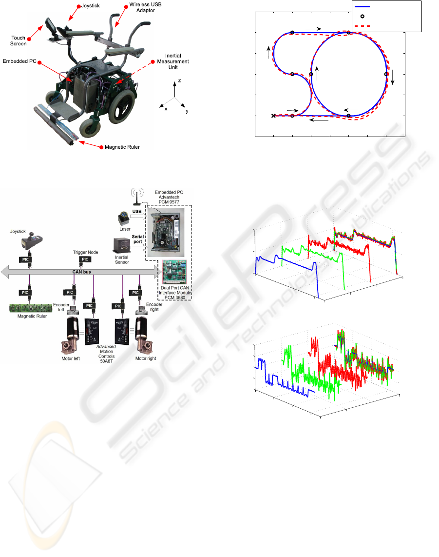
Figure 6: RobChair platform.
Figure 7: RobChair hardware architecture.
based on the time-triggered protocol paradigm, was
designed and implemented. All events are synchro-
nized by a message, sent from a Synchronization
Micro-Controller Unit (Trigger Node, in Fig. 7), that
synchronizes the other Micro-Controller Units, and
defines the control loop time reference.
The odometric data provided by the wheel en-
coders is fused with the data from magnetic mark-
ers. The extended Kalman filter (EKF) was chosen for
the fusion process (Bento et al., 2005). This naviga-
tion technology, based on sensing magnetic markers,
is well suited when high precision navigation and ro-
bustness is required, and it can be used to complement
other navigation systems, such as GPS.
The inertial sensor RGA300CA-100 (Crossbow)
was used for measuring the wheelchair accelerations
in three orthogonal directions.
Experimental results of the SM-TT controller us-
ing the planned path presented in Fig 1, are shown
−1 0 1 2 3 4 5 6 7
−1
0
1
2
3
4
5
x [m]
y [m]
Path
Desired Path
Magnetic Marker
EKF
FINISH
START
Figure 8: Experimental sliding-mode trajectory-tracking
control using an EKF-based fusion in the on-line pose es-
timation.
vd, vc, vr
vr
vc
vd
0
20
40
60
0
0.5
1
time [s]
Linear Velocity [m/s]
wd, wc, wr
wr
wc
wd
0
20
40
60
−1
−0.5
0
0.5
1
time [s]
Angular Velocity [rad/s]
Figure 9: Desired (v
d
, ω
d
), command (v
c
, ω
c
) and real
(v
r
, ω
r
) linear/angular velocities for SM-TT control under
magnetic-markers navigation (case B).
in Figs. 8- 10. Figure 9 shows desired, command
and real linear and angular velocities for SM-TT con-
trol under magnetic-markers navigation. Corrections
in the pose after each magnetic marker detection pro-
vokes an error signal that is efficiently dealt by the
SM-TT controller, and rapidly the tracking errors con-
verge to zero (see Fig. 10).
The analysis of user comfort is made in three dif-
ferent situations:
• case A: SM-TT control under odometry naviga-
tion;
ICINCO 2008 - International Conference on Informatics in Control, Automation and Robotics
42
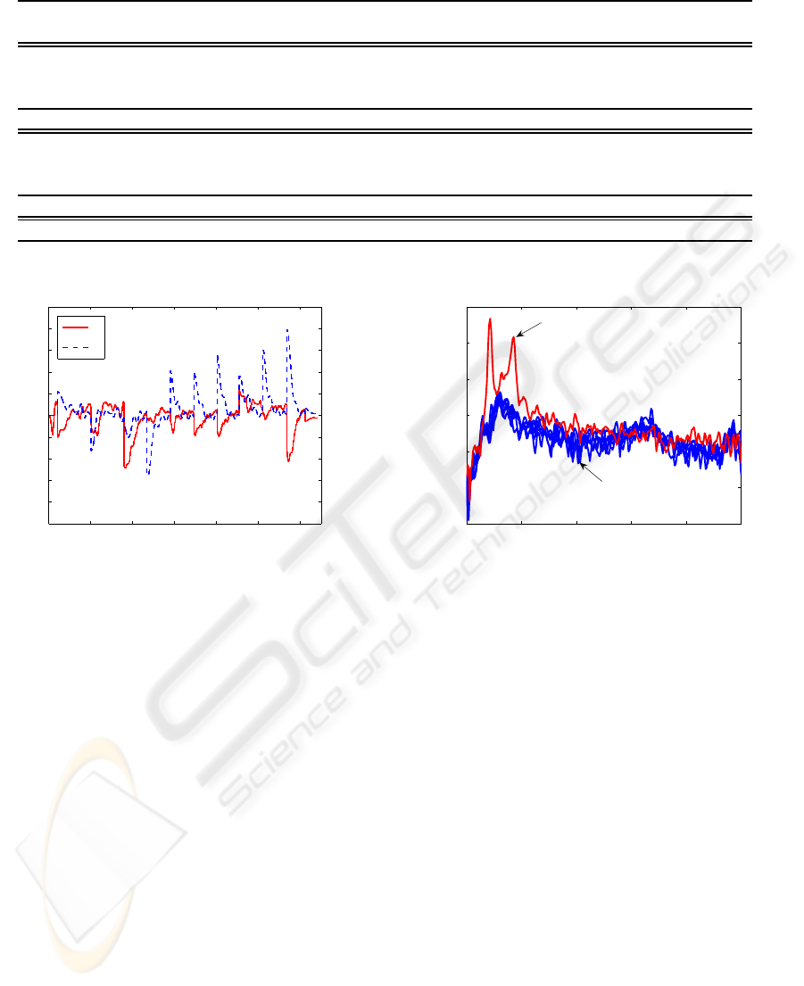
Table 3: Experimental Results.
Case No VDV
x
VDV
x
T
r
RMS accel. Max. accel RMS accel. Max. accel
RobChair Head RobChair RobChair Head Head
I 2.9219 1.3826 0.4732 0.3287 1.5686 0.1656 0.7286
A II 2.7634 1.3429 0.4859 0.3191 1.4988 0.1589 0.7307
III 2.7177 1.2802 0.4710 0.3187 1.5590 0.1510 0.8210
average 2.8010 1.3352 0.4767 0.3222 1.5421 0.1585 0.7601
I 2.9481 1.4408 0.4887 0.3538 1.2853 0.1797 0.7100
B II 3.2946 1.5707 0.4767 0.3663 1.7635 0.1856 0.7988
III 3.0318 1.4860 0.4901 0.3629 1.4136 0.1828 0.7755
average 3.0915 1.4992 0.4852 0.3610 1.4875 0.1827 0.7614
C - 11.4623 5.4607 0.4764 1.5185 4.1708 0.7039 2.2210
0 10 20 30 40 50 60
−0.25
−0.2
−0.15
−0.1
−0.05
0
0.05
0.1
0.15
0.2
0.25
Longitudinal and lateral errors [m]
time [s]
x
e
, y
e
[m]
x
e
y
e
Figure 10: Longitudinal and lateral errors for SM-TT con-
trol under magnetic-markers navigation (case B).
• case B: SM-TT control under magnetic-markers
navigation (odomeric data is fused, using an EKF-
based fusion, with absolute position data from
magnetic markers detection);
• case C: SM-TT control with purposely-
incorrectly-tuned parameters.
The experimental data of all three cases are summa-
rized in Table 3. Three experimental trials were ex-
ecuted in cases A and B. The table shows the vi-
bration dose value (VDV), transmissibility (T
r
), root
mean square accelerations (RMS) and maximum val-
ues (Max). The results of columns ”RMS accel.
Robchair” and ”Max. accel. RobChair” concern the
acceleration results obtained by the inertial sensor;
and the ”RMS accel. Head” and ”Max. accel. Head”
were obtained from the model of head-neck complex
(10). The overall rms acceleration of head (along the
x axes) in cases A and B are in range of ”not uncom-
fortable”, but in caseC is in range of ”uncomfortable”
(see Table 1 and equation (4)).
Each experiment was made for the same trajec-
tory (see Fig. 1). The time domain VDV values ob-
0 2 4 6 8 10
−50
−40
−30
−20
−10
0
10
Frequency (Hz)
Power/frequency (dB/Hz)
Cross PSD Estimate via Welch
C
A, B
Figure 11: Cross-spectal density functions for all experi-
ments.
tained in cases A and B are below the limit value of
9.1ms
−1.75
, only in caseC, VDV values are abovethat
limit. As can be observed from Table 3, the transmis-
sibility tends to be under unity, suggesting that the
vibrations are attenuated.
Figure 11 shows cross-spectral density values for
all experiments. The maximum of H
CSD
magnitude
occurs in case C, and the corresponding frequencies
are between 0.8 − 1.8Hz. When the magnitude of
H
CSD
increases, the user comfort decreases.
5 CONCLUSIONS
Wheelchair is exposed to vibration coming not only
from a variety of different road surface but also
from the command of the wheelchair (manually -
using Joystick or automated - using different type
of controllers). The paper analyzes the comfort of
wheelchair users when a SM-TT controller is used.
The user comfortis examined not only in time domain
(using the fourth power VDV), but also in frequency
ROBOTIC WHEELCHAIR CONTROL CONSIDERING USER COMFORT - Modeling and Experimental Evaluation
43

domain (using the cross-spectral density method).
Outdoor experiments, using RobChair with SM-TT
controller were performed. The experimental tests
presented in this paper are representative of the av-
erage performance of the controllers. We had sum-
marized our acquired experience in general observa-
tions that can be useful guidelines for implementation
of the same control strategies in other type of mobile
robots.
ACKNOWLEDGEMENTS
This work was supported in part by ISR-
Coimbra and Portuguese Technology and Sci-
ence Foundation (FCT), under contract NCT04:
POSC/EEA/SRI/58016/2004. R.Solea acknowledges
a PhD research fellowship from FCT.
REFERENCES
Atapourfard, M., Ishihara, T., and Inooka, H. (2002). The
influences of trunk horizontal vibration to the head-
neck complex. In SICE02, pages 1053–1058, Osaka.
Atapourfard, M., Ishihara, T., and Inooka, H. (2004). Iden-
tification of the head-neck complex in response to
trunk horizontal vibration. Biological Cybernetics,
90(6):418–426.
Bento, L., Nunes, U., Moita, F., and Surrecio, A. (2005).
Sensor fusion for precise autonomous vehicle naviga-
tion in outdoor semi-structured environments. In 8th
IEEE International Conference on Intelligent Trans-
portation Systems (ITSC’05), pages 245–250, Vienna.
Chwa, D. (2004). Sliding-mode tracking control of non-
holonomic wheeled mobile robots in polar coordi-
nates. IEEE Transactions on Control Systems Tech-
nology, 12(4):637–644.
Chwa, D., Hong, S., and Song, B. (2006). Robust posture
stabilization of wheeled mobile robots in polar coordi-
nates. In 17th International Symposium on Mathemat-
ical Theory of Networks and Systems, pages 343–348,
Kyoto.
European-Parliament and the Council of the Euro-
pean Union (2002). On the minimum health and safety
requirements regarding the exposure of workers to the
risks arising from physical agents (vibration). Offi-
cial Journal of the European Communities, Directive
2002/44/EC.
Fleury, S., Herrb, M., and Chatila, R. (1997). Genom: A
tool for the specification and the implementation of
operating modules in a distributed robot architectures.
In IEEE of the International Conference on Intelligent
Robots and Systems, pages 842–848, Grenoble.
Gao, W. and Hung, J. (1993). Variable structure control of
nonlinear systems: A new approach. IEEE Transac-
tions on Industrial Electronics, 40(1):45–55.
Gurses, S., Dhaher, Y., Hain, T., and Keshner, E. (2005).
Perturbation parameters associated with nonlinear re-
sponses of the head at small amplitudes. CHAOS,
15(2):023905.
ISO-2631 (1997). Mechanical vibration and shock - Eval-
uation of human exposure to whole body vibration -
Part 1: General requirements. International Organi-
zation for Standardization.
Kitazaki, S. and Griffin, M. (1997). A modal analysis of
whole-body vertical vibration using a finite element
model of the human body. Journal of Sound and Vi-
bration, 200(1):83–103.
Lopes, A. C., Moita, F., Nunes, U., and Solea, R. (2007). An
outdoor guidepath navigation system for AMRs based
on robust detection of magnetic markers. In 12th IEEE
International Conference on Emerging Technologies
and Factory Automation, pages 989–996, Patras.
Maia, R. (2004). Movimento de robots moveis com rodas
de tracao diferencial: modelacao e controlo do sistema
motriz. Master’s thesis, Universidade de Coimbra (in
portuguese), Coimbra.
Pires, G. and Nunes, U. (2002). A wheelchair steered
through voice commands and assisted by a reactive
fuzzy-logic controller. Journal of Intelligent and
Robotic Systems, 34:301–314.
Solea, R. and Nunes, U. (2007). Trajectory planning and
sliding-mode control based trajectory-tracking for cy-
bercars. Integrated Computer-Aided Engineering, IOS
Press, 14(1):33–47.
Solea, R., Nunes, U., and Filipescu, A. (2006). Trajec-
tory planning and sliding-mode control for WMR
trajectory-tracking and path-following respecting hu-
man comfort travel. In 7th Portuguese Conference on
Automatic Control - CONTROLO’2006, Lisbon.
Yang, J. and Kim, J. (1999). Sliding mode control for
trajectory tracking of nonholonomic wheeled mobile
bobots. IEEE Transactions on Robotics and Automa-
tion, 15(3):578–587.
ICINCO 2008 - International Conference on Informatics in Control, Automation and Robotics
44
