
WIRELESS MULTIMEDIA
CONTINUOUS PACKET CONNECTIVITY (CPC), POWER
AMPLIFIER (PA) BACK-OFF AND THE CUBIC METRIC (CM)
Terence E. Dodgson and Mark Horgan
Siemens Roke Manor Research Ltd., Romsey, Hampshire, SO51 0ZN, United Kingdom
Keywords: UMTS, WCDMA, Radio Coverage, Resource Efficiency, Cubic Metric, Continuous Packet Connectivity.
Abstract: With the every-increasing complexity of (e.g. multi media) signal waveforms generated by transmitters of
modern digital communications systems, there comes a corresponding demand for transmitters to continue
to operate efficiently (e.g. from a cost per bit and power output point of view) and to produce minimum
distortion, within specified limits. This paper looks at how a particular CPC scheme (for efficient resource
usage) might be devised and what the resulting impact is on the CM measure. The work uses, as a basis for
simulations, mainly the Uplink of the third generation (3G) Wideband Code Division Multiple Access
(WCDMA) Release six (R6) system.
1 INTRODUCTION
When looking at services which require high user bit
rates, wireless communication systems have tended
to lag behind wired systems due to problems caused
by the less benign radio transmission environment.
To the end user however, service is all important.
The current perception is that users would like to
have the same service offered over a wireless link as
they would be able to obtain over a wired one. This
has led to the design of cellular wireless systems
which are capable of working with relatively high
data rates, in particular over the wireless link.
2 CONTINUOUS PACKET
CONNECTIVITY (CPC)
The increase in data rate that allows for the delivery
of enhanced user services needs to be complimented
by the “efficient” delivery of that service, that is to
say, resources should not be needlessly wasted.
Optimisation of system resource is a necessary task
in order to drive down the cost per bit to the end
user. Multi-media (e.g. internet) service users
require relatively high data rates combined with low
data access delays. Internet sessions tend to be
bursty in nature, with defined periods of activity and
inactivity. Users require that they stay in a CPC
mode during periods of inactivity, i.e. they should
stay continuously connected. To ensure efficient
resource usage, users should be assigned only the
minimum resources which would allow them to
remain connected during these inactive times.
The CPC scheme given in Section 5 is thus
aimed at reducing the power level of the Uplink
(UL) Dedicated Physical Control Channel (DPCCH)
when there is no data to be transmitted on the UL
Enhanced Dedicated Physical Data Channel (E-
DPDCH).
3 CUBIC METRIC
HSDPA and HSUPA/E-DCH involve the
deployment of an increased number of channels and
associated channel configurations. The way these
channels are configured, and their subsequent
processing by the PA, has an impact on PA
distortion. In the past (i.e. with second generation,
2G, systems) the calculation of a signal’s PAPR has
been sufficient to determine what the PA back-off
should be. However, recent literature e.g. (3GPP
TSG RAN WG4#31, 2004), (3GPP TSG RAN
WG4#33, 2004), (3GPP TSG RAN WG4#38, 2006),
(Rohde & Schwarz, see ref) has suggested that the
PAPR measure is not sufficiently accurate when
working with the, increasingly, complex signals that
occur with enhanced 3G systems. Reference (3GPP
101
E. Dodgson T. and Horgan M. (2007).
WIRELESS MULTIMEDIA CONTINUOUS PACKET CONNECTIVITY (CPC), POWER AMPLIFIER (PA) BACK-OFF AND THE CUBIC METRIC (CM).
In Proceedings of the Second International Conference on Wireless Information Networks and Systems, pages 101-104
DOI: 10.5220/0002145801010104
Copyright
c
SciTePress
TSG RAN WG4#31, 2004) indicates that the CM
has the required accuracy for determining what the
PA back-off should be for any given channel format
and combination for current, modern, cellular
systems, such as WCDMA.
4 CM DERIVATION
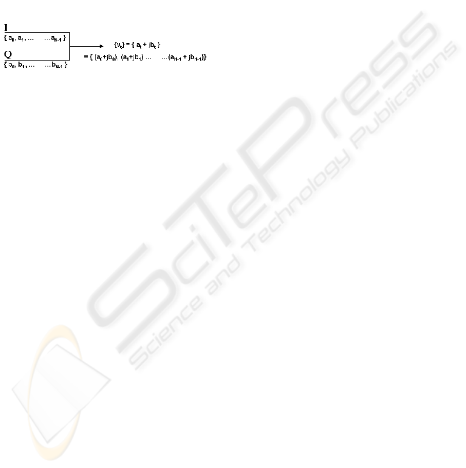
Modulator output can be represented as a complex
stream of N samples, {v
t
}, as indicated in Figure 1;
Figure 1: Modulation Output.
From the literature, e.g. (3GPP TS 25.101 v6.12.0,
see ref), the CM is given by;
CM = CEIL([ 20*log10( (v_norm
3
)
rms
) -
20*log10( (v_norm_ref
3
)
rms
) ] / k)
(1)
Where,
v_norm is the normalised voltage waveform of the
input signal
- v_norm_ref is the normalised voltage
waveform of the reference signal (12.2kbps
AMR Speech) and 20*log10(
(v_norm_ref3)rms = 1.52dB
- k is 1.85 for signals where all
channelisation codes meet the following
criteria CSF,N where N < SF/2
- k is 1.56 for signals whe
- re any channelisation codes meet the
following criteria CSF,N where N > SF/2
- CEIL{x,0.5} means rounding upwards to
the nearest 0.5dB, i.e. CM ∈
[0,0.5,1.0,1.5,2.0,2.5,3.0,3.5
A more explicit form of the CM can be derived;
CM = CEIL([20*log10(c
rms
) -
20*log10(
ref
c
rms
)]/ k)
(2)
where,
c
rms
= N. ( (P
cubed
)/(P
total
3
) )
(1/2)
(3)
5 CPC CONCEPT
HSUPA/E-DCH defines a new radio interface for
the uplink communication, with the main overall
goal of improving coverage and throughput as well
as reducing the delay of the uplink dedicated
transport channels.
The key technical capabilities introduced with
HSUPA/E-DCH are;
1) A new, dedicated Transport Channel, the uplink
E-DCH which maps onto a group of new
Physical Channels for both signalling and traffic.
2) Introduction of Hybrid Auto Repeat ReQuest (H-
ARQ) - including Chase and Incremental
Redundancy (IR) combining.
3) Fast Node B Scheduling to control the Set of
Transport Formats, within set Radio Network
Controller (RNC) limits, from which each User
Equipment (UE) may choose – enabling
improvement in coverage and capacity in the
uplink.
4) Fast Retransmissions based on a H-ARQ
Protocol for error recovery at the Physical layer.
From item (1), the introduction of a new dedicated
Transport Channel (and the resulting increase in the
number of uplink Physical channels) has the knock-
on effect of increasing the PAPR and puts higher
requirements on accurately specifying the required
back off of the UE Power Amplifier.
During Multimedia (e.g. internet) sessions UE’s
should be assigned minimum resources during
inactive periods. During an inactive period a user
may be, for example, reading recent information
obtained as a result of a request sent to an
appropriate website, before responding – and
thereby moving into an active period of the session.
In particular it may not be necessary for inactive
UEs to continue communications using a relatively
high power level for control signalling when lower
power levels may be sufficient. If control signalling
power is reduced, the level of cell interference is
correspondingly reduced and more users are able to
be catered for in a cell (and in this way the system
becomes more efficient).
One way in which this could be carried out is to
use a concept referred to as SIR_target reduction, i.e.
Layer 1 signalling (3GPP TR 25.903 v0.4.0, see ref),
which is applied by the Node B when inactivity of
some UE on the E-DCH is detected. This detection
might in fact be done looking at the corresponding
Medium Access Control (MAC) packet activity. The
Layer 1 signalling amounts to the Node B reducing
the Uplink (UL) SIR target to a predetermined value
(the Radio Network Controller, RNC, is not
involved in the immediate process and thus
relatively long delays associated with Radio
Resource Control, RRC, are avoided and the user
stays in the cell dedicated channel, CELL_DCH,
state). The predetermined value is set to a level
which ensures reliable transmit power control (TPC)
detection. WCDMA inner loop power control then
converges to this, reduced target, value, thus
WINSYS 2007 - International Conference on Wireless Information Networks and Systems
102
reducing the transmit power of the UL Dedicated
Physical Control Channel (DPCCH) and thereby
also reducing overall cell noise/interference.
As an example, the above, SIR_target reduction
scheme might use the following UL channels during
its application;
1) Dedicated Physical Control Channel (DPCCH)
which consists of;
a. Two Transmit Power Control, TPC, bits, and,
b. Eight Pilot Bits.
2) High Speed Dedicated Physical Control Channel
(HS-DPCCH) which consists of;
a. Channel Quality Indication (CQI) bits
b. Acknowledgement/Negative
Acknowledgement (ACK/NACK) bits
Having reduced the power usage (and hence
interference) during periods of inactivity, a method
is then required to ensure that signals (on the HS-
DPCCH) are transmitted at their correct levels when
UEs are then active (e.g. when new data arrives in
the UL MAC-enhanced dedicated channel, MAC-e,
buffer). This is achieved through β boosting (3GPP
TR 25.903 v0.4.0, see ref). SIR_target reduction
together with β boosting allows UEs to operate in
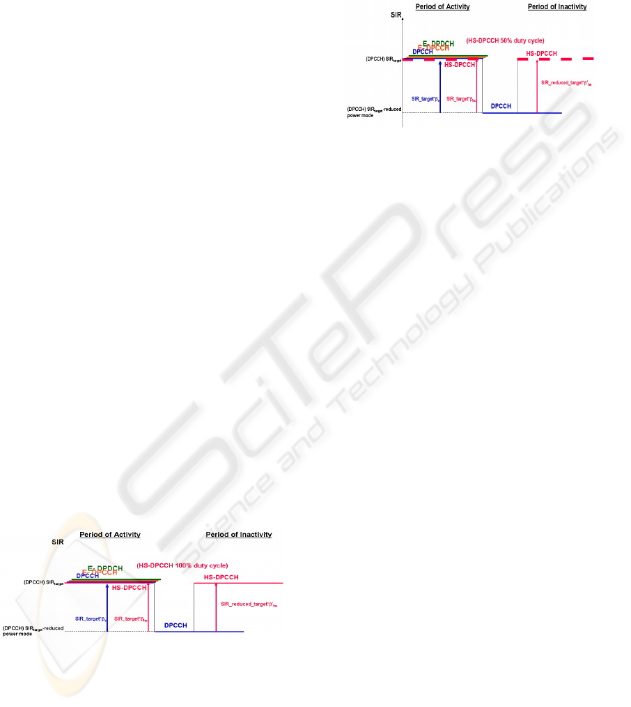
CPC fashion. Figure 2 and Figure 3 show a
simplistic view of waveforms during active and
inactive periods.
In order to obtain any gain during the active
periods the total transmit power of the DPCCH and
the HS-DPCCH after SIR_target reduction and
boosting should be less than the total transmit power
that occurs when using normal SIR target operation.
It is noted that the two methods of operation may not
result in the same performance results since there
may be a penalty associated with knock-on effects of
channel estimation under (possibly) worse
conditions (3GPP TR 25.903 v0.4.0, see ref).
Figure 2: Signal to Interference Ratio (SIR)/Power of
Waveforms during periods of activity and inactivity, for a
100% HS-DPCCH duty cycle.
It is noted that the 3GPP standard of ref (3GPP TS
25.213 v6.5.0, see ref) indicates how to set the
β
(gain) values of appropriate signals. Of particular
interest is the β
hs
value, as derived from a quantized
amplitude ratio,
A
hs
, which is translated from Δ
ACK
,
Δ
ΝACK
and Δ
CQI
signalling coming from higher layers.
Δ
ACK
, Δ
ΝACK
and Δ
CQI
are carried by the HS-DPCCH
channel and are associated with acknowledgment,
negative acknowledgement and channel quality
indication respectively
.
Figure 3: Signal to Interference Ratio (SIR)/Power of
Waveforms during periods of activity and inactivity, for a
50% HS-DPCCH duty cycle – indicated by equally spaced
dashed lines.
6 SIGNAL GENERATION
& RESULTS
In order to estimate whether the proposed CPC
scheme, is likely to lead to distortion effects due to
incorrect PA back-off setting (through determination
of the CM), representative signals are simulated and
the CM calculation is performed. Comparison of
calculated CMs of other 3G WCDMA R6 signals is
then undertaken (with and without the inclusion of
the proposed CPC scheme). Using the empirical
results from ref (3GPP TSG RAN WG4#31, 2004),
in the form of a graph, the calculated CM values can
be mapped onto the required PA power back-off
values. From these simulations, comparisons, and
mapping a conclusion might then be reached as to
whether such a scheme would significantly add
distortion when such CPC signals are processed and
transmitted by the PA. decibels (dBs) above the
DPCCH.
Table shows some of the various signals
considered – Signal A is the reference signal (3GPP
TSG RAN WG4#31, 2004), (3GPP TSG RAN
WG4#33, 2004), (3GPP TS 25.101 v6.12.0, see ref
This signal can be used to verify the “raw CM”
value of 0.0. Values obtained are in agreement with
the previous literature. Signals B to I are those
which might occur when the CPC scheme is
implemented, i.e. they reflect various power offsets
during an inactive period and which might be the
result of boosting the β
hs
value so that the HS-
DPCCH is a certain number of decibels (dBs) above
the DPCCH.
WIRELESS MULTIMEDIA Continuous Packet Connectivity (CPC), Power Amplifier (PA) Back-off and the Cubic Metric
(CM)
103
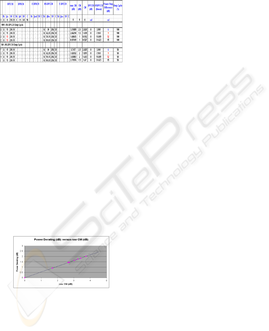
Table 1: Considered Signals.
Note: the raw_CM value does not include
normalization by the factor K of ref (3GPP TS
25.101 v6.12.0, see ref), and does not include the
quantization indicated by the “CEIL” (rounding up
to the nearest 0.5dB) function found in the same
reference. The column headed CM(dB) does take
this into account and values are seen to stay within
the 0 to 3dB range (consistent with the requirement
of ref (3GPP TS 25.101 v6.12.0, see ref)).
Values for β
hs
of 42.25, 59.76 and 84.43
correspond to power offsets, 20log
10
(β
hs
/β
c
), of
20log
10
(42.25/15),20log
10
(59.76/15),20log
10
(84.43/
15), i.e. 9dB, 12dB and 15dB respectively.
It is noted that the relationship of PAPR or the
CM to amplifier back-off are derived empirically,
e.g. (3GPP TSG RAN WG4#31, 2004), (3GPP TSG
RAN WG4#33, 2004) using a limited number of
amplifiers, with curves fitted to experimentally
obtained data. Using these references and the
resulting empirical result, the raw_CM values of
decibels (dBs) above the DPCCH.
Table are mapped onto the corresponding power
back-off value. The resulting graph can be seen in
Figure 4.
Figure 4: PA De-rating/Back-off versus raw_CM (dB).
The points on the graph are the simulation results mapped
onto the PA back-off value.
7 CONCLUSION
The PAPR or CM relationship with amplifier back-
off is dependent on the complexity of modulated
signals. For current systems, the PAPR/CM versus
PA back-off relationship can be determined
empirically through the generation of appropriate
Uplink Modulated Waveforms. The CM is a value
which can be determined through simulation (as in
this paper).
Through comparison of appropriately modulated
waveforms that comprise the CPC scheme given in
this report, it has been seen that such a scheme
produces CM values close to those of similar non
CPC waveforms, laying in the same 0 to 3dB range
(3GPP TSG RAN WG4#31, 2004), (3GPP TSG
RAN WG4#33, 2004), (3GPP TSG RAN WG4#38,
2006).
It can therefore be concluded that the impact of
the reported CPC scheme on the CM and the
subsequent PA amplifier back-off is no worse than
that which currently exists, i.e. when no such CPC
scheme is implemented. Indeed, if an issue had been
found, or is ever found, it would undermined the
CMs usage suitability, in terms of its ability to be
used with any channel combination and format and
any system concept.
Implementation of any CPC scheme that alters
the gain value of the HS-DPCCH requires that the
appropriate standard, e.g. ref (3GPP TS 25.213
v6.5.0, see ref), or future standards are modified to
reflect the change in relationship between the HS-
DPCCH and the DPCCH.
Finally, a different (more explicit) procedure
from that of (3GPP TS 25.101 v6.12.0, see ref) has
been derived in this paper.
REFERENCES
3GPP TSG RAN WG4#31, Tdoc#R4-040367,
“Comparison of PAR and Cubic Metric for Power De-
rating”, Beijing, China, May 10-14, 2004.
3GPP TSG RAN WG4#33, Tdoc#R4-040721, “Mapping
of cubic metric to additional PA headroom”, Shin-
Yokohama, Japan, 15-19 November 2004.
3GPP TSG RAN WG4#38, Tdoc#R4-060343, Change
Request “UE maximum output power with HS-
DPCCH and E-DCH”, Denver, Colorado, USA, 13th
– 17th February 2006.
Rohde & Schwarz, Application Note, “High Speed
Downlink Packet Access (HSDPA): “Challenges for
UE Power and Amplifier Design”, http://www.rohde-
schwarz.com.
3GPP TS 25.213 v6.5.0, “Spreading and Modulation
(FDD) Release 6”, Section 4.2.1.1.
3GPP TS 25.214 v6.9.0, “Physical Layer Procedures
(FDD) Release 6”, Section 5.
3GPP TR 25.903 v0.4.0, “Continuous Connectivity for
Packet Data Users, Release 7”, Section 4.3.
3GPP TS 25.101 v6.12.0 “User Equipment (UE) radio
transmission and reception (FDD) Release 6”, Section
6.2.2.
WINSYS 2007 - International Conference on Wireless Information Networks and Systems
104
