
IMPROVED MESHLESS DEFORMATION TECHNIQUES FOR
REAL-TIME INTERACTIVE COLLABORATIVE ENVIRONMENTS
Alex Henriques and Burkhard W¨unsche
Graphics Group, Department of Computer Science, University of Auckland, New Zealand
Keywords:
Deformable models, real-time simulation, interaction techniques, shape matching, virtual environments.
Abstract:
Meshless deformation based on shape matching is a new technique for simulating deformable objects without
requiring mesh connectivity information. The approach focuses on speed, ease of use and stability at the
expense of physical accuracy. In this paper we introduce improvements to the technique that increase physical
realism and make it more suitable for use in interactive real-time environments such as games and virtual
surgery applications. We also present intuitive real-time interaction techniques for picking, pushing and cutting
objects simulated using meshless deformation based on shape matching. For deformable collision detection
and response, we present a new method for surface meshes based on previous volumetric methods.
1 INTRODUCTION
Advances in graphics hardware and rendering tech-
niques have made real-time interactive virtual en-
vironments increasingly realistic. In the past few
years such applications and in particular computer
games have started to incorporate rigid-body physics,
which are easily controlled and readily simulated us-
ing fast libraries like ODE (Smith, 2006). As process-
ing power increases further and physics cards are in-
troduced, the natural progression is to include real-
time deformable object simulation into virtual envi-
ronments.
In 2005 meshless deformation based on shape
matching was introduced as a new technique for sim-
ulating deformable objects (M¨uller et al., 2005). The
technique is fast, easy to use, unconditionally sta-
ble, and has low memory requirements. These factors
make the technique particularly interesting for virtual
surgery applications and highly interactive real-time
environments like computer games.
In this paper we present improvements to this
technique. Soft caps on surface area expansion are
introduced to create a natural limit on deformations.
A modification is introduced to prevent inverted ob-
ject states. We also present efficient interaction tech-
niques, i.e. picking, pushing and cutting, for use with
objects simulated using meshless deformation based
on shape matching. Finally, we adapt for use with
surface meshes a tetrahedral based collision detection
and response method. All methods and interaction
techniques can be executed in real time and easily
integrated into traditional 3D rendering or game en-
gines.
Section 2 introduces the meshless deformation
technique in more detail, while section 3 details our
improvements to the technique. Section 4 describes
the interaction techniques available in the applica-
tion we have developed, and section 5 describes the
collision detection and response methods we imple-
mented. Finally, section 6 summarizes our results,
and section 7 concludes.
2 MESHLESS DEFORMATION
“Meshless Deformations Based on Shape Matching”,
or meshless deformation for short, was recently de-
veloped as a technique for dynamically simulating
deformable objects (M¨uller et al., 2005). The ap-
proach is geometrically motivated, requires no pre-
processing, and is both simple to compute and uncon-
ditionally stable.
154
Henriques A. and Wünsche B. (2007).
IMPROVED MESHLESS DEFORMATION TECHNIQUES FOR REAL-TIME INTERACTIVE COLLABORATIVE ENVIRONMENTS.
In Proceedings of the Second International Conference on Computer Graphics Theory and Applications - AS/IE, pages 154-161
DOI: 10.5220/0002085501540161
Copyright
c
SciTePress

Figure 1: First, the original shape x
0
i
is matched to the de-
formed shape x
i
. Then, the deformed points x
i
are pulled
towards the matched shape g
i
(adapted from (M¨uller et al.,
2005)).
2.1 The Technique
In meshless deformation, each object is represented
by a set of points, or point cloud. No connectivity in-
formation is required. Each point in the point cloud
moves and responds to forces independently of other
points, while meshless deformation ensures the ob-
ject retains its overall shape. Let the initial config-
uration (i.e. positions) of points be x
0
i
, and the de-
formed configuration of points at some later time be
x
i
. To preserve the object’s shape, Meshless Deforma-
tion moves and rotates the initial shape x
0
i
as closely
as possible onto the actual shape x
i
(see figure 1). The
translated and rotated initial shape now defines the set
of goal positions g
i
. Every timestep, each point is
moved a fraction α of the way towards its goal posi-
tion. This gives the point cloud a tendency to preserve
its initial shape.
The optimal transformation from x
0
i
to g
i
mini-
mizes the sum of the squared distances between g
i
and
x
i
. The problem is the same as that of “absolute ori-
entation”: given coordinates of a set of points as mea-
sured in two different Cartesian coordinate systems,
find the optimal transformation between them (Horn,
1987). This corresponds to minimizing the following
sum.
∑
i
w
i
R(x
0
i
− t
0
) + t− x
i
2
where R is a pure rotation matrix. In meshless de-
formation, the weights are the point masses, t
0
is the
centre of mass of the initial shape, and t is the cen-
tre of mass of the current shape. This equation can
be extended to allow linear and quadratic matching
by replacing R with a linear deformation matrix A or
quadratic deformation matrix
e
A. Linear deformations
allow stretch and shear, while quadratic deformations
additionally allow bends and twists. A tendency to-
wards the undeformed state is introduced by combin-
ing A or
e
A with R, resulting in a final deformation
matrix F.
F = β
e
A+ (1− β)R (1)
where β is a user defined constant between 0 and
1. When β is low, the tendency is largely towards a
rigid undeformed state; when β is high, the tendency
is more towards the quadratic match, resulting in a
softer more deformable object.
2.2 Clusters
Because meshless deformation matches a quadrati-
cally deformed version of the initial object, deforma-
tion is limited to combinations of stretch, shear, bend
and twist over the entire object. This means local de-
formations – those deforming only one part of an ob-
ject – are impossible. Higher order deformations, e.g.
the cubic deformation of a string given two bends, are
also impossible.
As a partial solution to these limitations, M¨uller et
al. divide the set of particles into overlapping clus-
ters with separate deformation matrices. This can
greatly increase the range of deformation. However,
applications are largely limited to objects with mostly
independent subparts that deform only quadratically.
More complex entities like cloth need to be divided
into finely grained clusters for plausible simulation.
But, this is inefficient and inaccurate, and better per-
formed by mass-spring systems.
3 IMPROVEMENTS
3.1 Surface Area Preservation
Meshless deformation matches a goal configuration
to the deformed point cloud as closely as possible.
However, the goal configuration matched frequently
has greater or lesser volume than the original object,
which is generally undesirable. To preserve volume,
meshless deformation scales the deformation matrix
such that the goal configuration’s volume is identi-
cal to the original object’s volume. The problem with
such blind scaling is that when for example a force
squashes the object along one dimension, the vol-
ume of the goal configuration pre-scaling can be very
small. To preserve volume the scaling factor must be
very large to compensate, and the other two dimen-
sions are scaled up drastically in response as illus-
trated in figure 2.
3.1.1 Suggested Solutions
If an airtight balloon filled with water were thrown
gently at a wall, the volume of water inside would
remain constant. But the balloon would not behave
as in figure 2, because of resistance to surface area
IMPROVED MESHLESS DEFORMATION TECHNIQUES FOR REAL-TIME INTERACTIVE COLLABORATIVE
ENVIRONMENTS
155

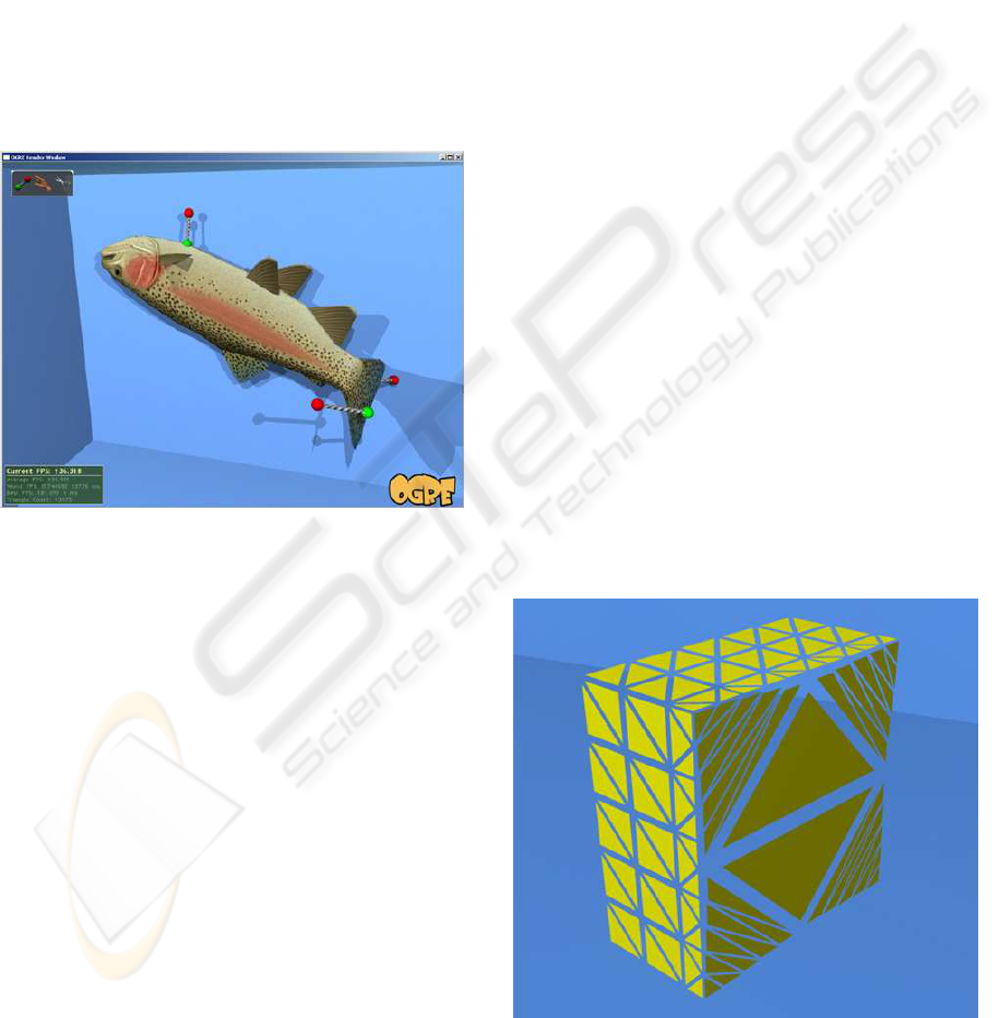
Figure 2: Volume preservation without surface area preser-
vation results in unrealistic surface expansion as a cube is
pushed into a wall.
stretch. Clearly then, a method to constrain surface
area is needed. Some algorithms use mesh-based ex-
plicit surface area preserving forces (Teschner et al.,
2004a). For meshless deformation, possible solutions
include the following:
1. Limit forces applied to objects. If the vertices are
not subject to large forces, they will not move so
far out of their original configuration that blind
volume-preservation scaling will produce such
extreme surface area changes.
2. Limit the maximum velocities of vertices. As with
1, if the vertex velocities are constrained to within
a maximum, extreme configurations will be more
difficult to produce.
3. Limit α and β. If α is large, the vertices will return
quickly to their goal positions, lessening the like-
lihood of extreme configurations being produced.
If β is small, the tendency of the cube to return
to an undeformed state will override the quadratic
transformation if it matches an extreme configu-
ration.
4. Have vertices propagate a constraint force through
to adjacent vertices.
5. Limit the transformation matrix somehow so that
it doesn’t match extreme configurations.
1, 2, and 3 used in various combinations are quite suc-
cessful in combating this problem. 4 is an interesting
option, but would require connectivity information to
be implemented efficiently. These methods also re-
quire tightly regulated parameters, so by definition
cannot be unconditionally stable. 5 on the other hand
is simple to implement, efficient, and can achieve un-
conditional stability.
The simplest way to constrain surface area using 5
is to cap the Frobenius norm of the linear deformation
matrix A.
kAk
2
F
=
m
∑
i=1
n
∑
j=1
|a
ij
|
2
Drastic increases in surface area are caused by
large stretch or shear values, which are the contrib-
utors to kAk
2
F
. Therefore, by limiting kAk
2
F
, we limit
stretch and shear. If we want to cap the amount of
quadratic deformation for visual reasons, the follow-
ing methods can also be trivially extended from A to
e
A. In the subsequent computations, we use the term
kAk as shorthand for the Frobenius norm.
3.1.2 Methods of Clamping
There are several ways to clamp kAk; here are three.
1. Let rows of A be termed r
i
. If any kr
i
k
2
exceeds a
user selected c
max
, scale r
i
by x such that kxr
i
k
2
=
c
max
.
2. Cap the magnitude of A at c
max
. To do this, if
kAk
2
> c
max
update A as
A ← γA+ (1 − γ)R
where R is the rotation matrix from equation 1
and γ is derived from the solution to the quadratic
equation
kγA+ (1− γ)Rk
2
= c
max
.
Note that because of the choice of c
max
the func-
tion is monotonically increasing when 0 ≤ γ ≤ 1
and hence the quadratic equation has exactly one
solution. The final matrix F in equation 1 is then
calculated as:
F = (γA+ (1 − γ)R)β+ R(1− β)
= γβA+ βR− γβR+ R− βR
= γβA+ (1− γβ)R.
hence γ is a simple beta modifier, i.e., it makes the
deformation more rigid.
3. As a cheaper imitation of 2, simply set
γ =
c
max
kAk
2
.
GRAPP 2007 - International Conference on Computer Graphics Theory and Applications
156

The first method works well, but restricts defor-
mation along each axis regardless of deformation in
the other axes. The second and third methods on the
other hand restrict the sum of deformations along all
axes, so maximum deformation along one axis pre-
vents further deformation along the other axes. The
appropriate method would seem to depend on the
physical properties of the object. Visually we could
not distinguish between methods 2 and 3.
3.1.3 Further Extensions
These three methods solve the blow-up problem well,
but introduce a slight problem with visual plausibility.
A soft object falling to the ground will flatten to the
point where the deformation magnitude φ is capped,
then deformation will jerk to a stop. To solve this
we suggest a “soft” cap rather than a hard one. This
would take the form of a monotonically increasing
function f such that for an intermediate threshold c
and a maximum threshold m,
f(φ) =
φ φ ≤ c
< m φ > c
In other words, an object with deformation mag-
nitude φ exceeding the soft cap c will have φ reduced
towards c. To prevent unrealistically large deforma-
tions, m indicates a hard cap below which φ will al-
ways be reduced. Here is an example function:
f(φ) =
(
φ φ ≤ c
m−
c
φ
(m− c) φ > c
3.2 Inversion
Recall that the central equation to be minimized in
meshless deformation is
∑
i
w
i
R(x
0
i
− t
0
) + t− x
i
2
M¨uller et al. present the most referenced solution
to this problem (referred to as that of absolute orien-
tation) derived in (Horn, 1987). In his paper however
Horn mentions that the R obtained may be a reflec-
tion, rather than a rotation, in cases where reflection
provides a better fit.
In traditional photogrammetric applications of the
absolute orientation problem, the data may seldom be
corrupted enough to produce a reflective R. When
applied to physical objects undergoing large defor-
mations however, the vertices can frequently be de-
formed enough that the optimal R is a reflection. The
inverted object produced is an unacceptable result for
homogeneous objects, because it would require mas-
sive self-penetration.
3.2.1 Determinant Cube Root Solution
M¨uller et al. do not specifically mention what to do
when a reflective R is produced. The only related
comment is made when discussing volume preserva-
tion of the linear transformation matrix A:
To make sure that volume is conserved, we di-
vide A by
3
p
det(A) ensuring that det(A) = 1.
When det(A) is negative,
3
p
det(A) is also negative.
The subsequent division results in an A that produces
a non-inverted, volume preserving goal position con-
figuration. This configuration is obtained however by
a simple reflection of each optimal position through
the origin. A no longer describes a minimization of
goal position with respect to vertex position. Thus the
goal positions will tend to be far away from their re-
spective vertex positions, and the integration step will
produce large velocities. The result is a blowup.
When taken literally, the method deals with an
inverted goal match by producing a blowup. If
3
p
det(A) is constrained to its absolute value, the
method results in a stable, inverted object configura-
tion. Neither result is acceptable.
3.2.2 Modified R Extraction Solution
Rather than make a modification to the transforma-
tion matrix after R has been calculated, a modified al-
gorithm is proposed by Umeyama (Umeyama, 1991)
that strictly produces an optimal rotation matrix R.
Implementing this modification involves only a sim-
ple addition to the singular value decomposition solu-
tion method of Arun et al. (Arun et al., 1987).
This method solves the inversion problem, but
only partially. While R will always be a rotation, A
may still contain a reflection (assuming the absolute
value of
3
p
det(A) is used). The final transformation
matrix F = βA + (1 − β)R then will always have a
tendency towards a non-inverted configuration. But
with β close to 1, the tendency will be slow, and
may produce physically implausible results. Ideally
A would calculated in a manner that never produced
reflections–this remains for future work.
4 INTERACTION TECHNIQUES
In order to make a virtual world more realistic it is
necessary to enable the user to interact with objects
in a believable manner. Simulating both the look and
feel of materials increases realism and the immersive
experience. Furthermore advanced interactions are
required for many applications such as virtual surgery
IMPROVED MESHLESS DEFORMATION TECHNIQUES FOR REAL-TIME INTERACTIVE COLLABORATIVE
ENVIRONMENTS
157
simulations. In this section we introduce techniques
for picking, constraining, pushing and cutting objects
simulated using meshless deformation based on shape
matching.
The picking mode allows the user to grab and ma-
nipulate any object vertex with a spring force. The
spring force acts towards the cursor position (repre-
sented by a red sphere), and can also be moved back
and forth along the camera’s look direction using the
mousewheel. Spring forces can be locked in place, al-
lowing the user to change modes or create new spring
forces. In this manner objects can readily be “fixed”
in deformed positions (see figure 3). This mode is
useful for precisely manipulating an object’s position,
deformation and orientation.
Figure 3: A deformed model of a trout fixed using two
locked pick points.
The pushing mode allows the user to manipulate
objects with a pushing force. The cursor position is
represented in 3D space as in the picking mode, and
collision response forces are applied to any objects
near the cursor. This mode is useful for moving sev-
eral objects at once, as when clearing a path or area.
4.1 Cutting
The cutting mode allows the user to sever objects into
separate pieces. The user controls a cutting imple-
ment which can be arbitrarily orientated in 3D space.
When the user holds down the left mouse button, the
two “blades” of the cutting implement converge, and
any intersecting objects are severed along the plane of
the cutting implement.
The cutting operation takes as input an object and
a cutting plane, and splits the object along that cut-
ting plane. This simplified version of the general cut-
ting problem does not allow partial cuts, and always
reveals a planar internal surface. We found it neces-
sary to disallow partial cuts for two reasons: Firstly,
partial cuts would require complex representations of
internal structures in order to correctly simulate sub-
sequent deformations. While objects could be defined
with an interior structure this would limit applica-
tions and efficiency. Alternatively an external surface
can be dynamically created (imagine cutting jelly),
but this can make cuts difficult to control precisely.
The second and more important problem with partial
cuts is that the area surrounding a partial cut needs to
undergo complex deformations in order to be repre-
sented realistically. An edge can sag, fray, and be de-
formed independently of the edge on the opposite side
of the cut. Meshless deformation–which allows only
quadratic deformation over the whole cluster–cannot
represent such complex and subtle deformations.
4.1.1 Cutting Implementation
Our cutting implementation cuts an object along a
plane as follows. First, all triangles completely in
the plane’s positive halfspace are discarded, while all
triangles completely in the plane’s negative halfspace
are kept. Triangles straddling the cutting plane are di-
vided into smaller subtriangles, creating a neat edge
aligned with the cutting plane. Finally, the newly cre-
ated vertices touching the cutting plane are fed into a
Delaunay triangulation algorithm, which seals up the
exposed cross-section (see figure 4). Possible future
improvements include adding vertices inside the ex-
posed cross-section to allow for more regular triangu-
lation.
Figure 4: After a cut, the exposed internal hole is sealed up
with a Delaunay triangulation.
GRAPP 2007 - International Conference on Computer Graphics Theory and Applications
158

5 COLLISION
Several types of methods are available for detecting
and responding to collisions between deformable ob-
jects. These include bounded volume hierarchies, sto-
chastic methods, distance fields, spatial subdivision,
and image-space techniques (Teschner et al., 2004b).
The collision detection and response techniques
used by M¨uller et al. (M¨uller et al., 2005) involve
spatial hashing (Teschner et al., 2003) and penetra-
tion depth estimation (Heidelberger et al., 2004) on
tetrahedral meshes. We give a brief overview of the
method here.
1. Using a spatial hashing approach, each point is
classified as colliding if it intersects a tetrahedron.
2. Colliding points are classified as border points if
they are connected by an edge to a non-colliding
point.
3. For each border point a penetration depth and di-
rection is calculated based on connected edges’
intersection points and corresponding surface nor-
mals.
4. Penetration depths and directions are propagated
inwards to the remaining colliding points in a
breadth-first manner.
One major disadvantage of this method is that it
requires a tetrahedral mesh. Many applications, for
example games, use only surface meshes. With this
in mind we adapted the method for use with surface
meshes.
In steps 1 and 2, we need to classify colliding and
border points without tetrahedra. Using spatial hash-
ing, we test each edge for intersection with nearby
surface mesh triangles. On intersection, we classify
the edge point in the triangle’s positive halfspace as
non-colliding, and the edge point in the triangle’s
negative halfspace as colliding. We also record the
length along the edge of the intersection point. If the
same edge intersects multiple triangles, the two edge
points’ classifications are with respect to their clos-
est triangle along the edge. The colliding points so
classified are the border points. Remaining points are
classified as colliding if they can be reached from a
border point without passing through a non-colliding
point.
Step 3 remains the same. Step 4 requires sig-
nificant modification however – figure 5b shows the
penetration depths and directions calculated without
modification. The problem here is that without a
tetrahedral mesh, border points only exist on the sur-
face of the mesh around the intersecting triangles, and
not inside the mesh around deeply penetrated areas.
Figure 5: (a) Ideal response forces. (b) Response forces cre-
ated using a consistent penetration depth estimation tech-
nique.
This results in unrealistic propagated penetration di-
rections. Rather than use propagation, for each non-
border colliding point we simply calculate the pen-
etration direction as a weighted sum of each border
point’s penetration direction, where the weights are
inversely proportional to the number of edges in the
shortest edge path between the colliding point and
border point. To calculate penetration depth, we find
the length of a ray cast from the colliding point to the
surface along the penetration direction. The results
are as in figure 5a.
Compared to the original tetrahedral method, our
surface mesh collision technique is slower and subject
to classification errors and erratic behaviour. While
the method works for simple applications further re-
search is necessary to make it more stable and hence
suitable for computer games and similar applications
where tetrahedral meshes are not available.
6 RESULTS
We have developed a framework for testing interac-
tive simulation environments and implemented within
it meshless deformation based on shape matching to-
gether with our improvements. The user may pick,
push or cut deformable objects in real time.
We found that simple objects with limited modes
of deformation are simulated best, while objects com-
posed of simple subcomponents are simulated well
with clusters. Objects with a very high number of de-
formation modes, such as cloth, cannot be simulated
efficiently (Rubin, 2006).
Due to the improvements implemented, extreme
forces and deformations no longer produce stable in-
versions or erratic behaviour due to temporary inver-
sions. Further, large forces no longer result in surface
area blowups, allowing the use of arbitrary stiffness
(α and β) values, forces and speeds. Objects that are
particularly soft or moving at great speeds no longer
IMPROVED MESHLESS DEFORMATION TECHNIQUES FOR REAL-TIME INTERACTIVE COLLABORATIVE
ENVIRONMENTS
159

jerk to a sudden stop when their deformations exceed
a certain amount, instead gradually reaching a maxi-
mum deformation between soft and hard caps.
Our experiments show that a variety of different
objects can be simulated plausibly. The simplest ex-
ample is a beach ball. We also found that a trout was
simulated quite well, being quite rubbery, with skin
not subject to local deformations. More complicated
objects such as a rubber torus were also simulated
well. This is probably because while complicated, the
object is not one users have a lot of experience with,
so deformation that isn’t physically accurate can read-
ily be seen as plausible. Contrast this with a realistic
human face model we experimented with. The defor-
mations of a human face are something we are inti-
mately familiar with, and any deviation from physical
accuracy can be easily noticed. We also found that
to achieve an acceptable range of deformations cor-
responding to the muscle groups of the face, clusters
needed to be divided very precisely – we had to im-
plement a special export tool to allow precise cluster
specification in a 3D modeling program. Even then,
we found clusters very difficult to manipulate into
giving plausible facial animations, and boundaries be-
tween clusters were often noticeable. The final type
of object we tested was skin. Skin requires local de-
formation at arbitrary points. To achieve this the skin
needed to be split up into many small clusters. The re-
sults were plausible, however with many clusters effi-
ciency is low. Cloth simulation led to similar results.
Usability. Informal user testing indicates that our
environment and all our interaction techniques were
intuitive and easy to use. The ability to push, pull,
fix and cut deformable colliding objects significantly
increased user enjoyment.
Ease of implementation. We found meshless de-
formation relatively easy to implement and integrate
into the 3D rendering engine Ogre. There are only
two main differences between current 3D engines
and what is required for deformable object simula-
tion. Firstly, rigid objects have static sharable meshes,
while deformable objects require updates to individ-
ual vertex positions every timestep on their own mesh
instance. Secondly, collision detection and response
is a much slower, more difficult task for deformable
objects.
Performance. Our environment is comparatively
fast: We can simulate dozens of simple 32 tetrahe-
dron objects with collisions in real time and uncondi-
tional stability (see figure 8). Suitable speed for sim-
ple virtual surgery applications could be achieved by
optimising our algorithms and/or implementing them
on the GPU. However where deformable behaviour is
less important, for example in most games, we predict
it will be at least several years before deformable ob-
ject simulation is the best marginal use of processing
power.
Tweakability. The “gooeyness” and stiffness of
each object can be easily modified using the α and
β parameters. Further collision-response parameters
can also be tweaked. The strength of surface area
preservation can be specified with a force response
curve. Volume preservation is automatic, but can be
adapted to use a force response curve as well.
Disadvantages. The primary disadvantage of our
environment is the lack of robust local deformation.
For complex virtual surgery applications which re-
quire plausible localized deformation of an arbitrary
region, our environment is less suitable. Also, even
when simulation is visually plausible, it is usually not
physically accurate.
Figure 6: Behaviour of a 5×5 cluster skin patch in response
to a user pick.
7 CONCLUSION
We have implemented an improved algorithm for
meshless deformation based on shape matching.
Our improvements include soft capped surface area
preservation, and the prevention of inverted states.
We have also implemented several interaction tech-
niques allowing users to interact with objects realisti-
cally and intuitively. Collision detection and response
have been implemented based on spatial hashing and
accurate penetration depth estimation techniques. We
have also adapted the collision method for use with
triangular surface meshes, for applications such as
games where tetrahedral meshes are not available. In-
formal user testing indicates that users find our envi-
GRAPP 2007 - International Conference on Computer Graphics Theory and Applications
160
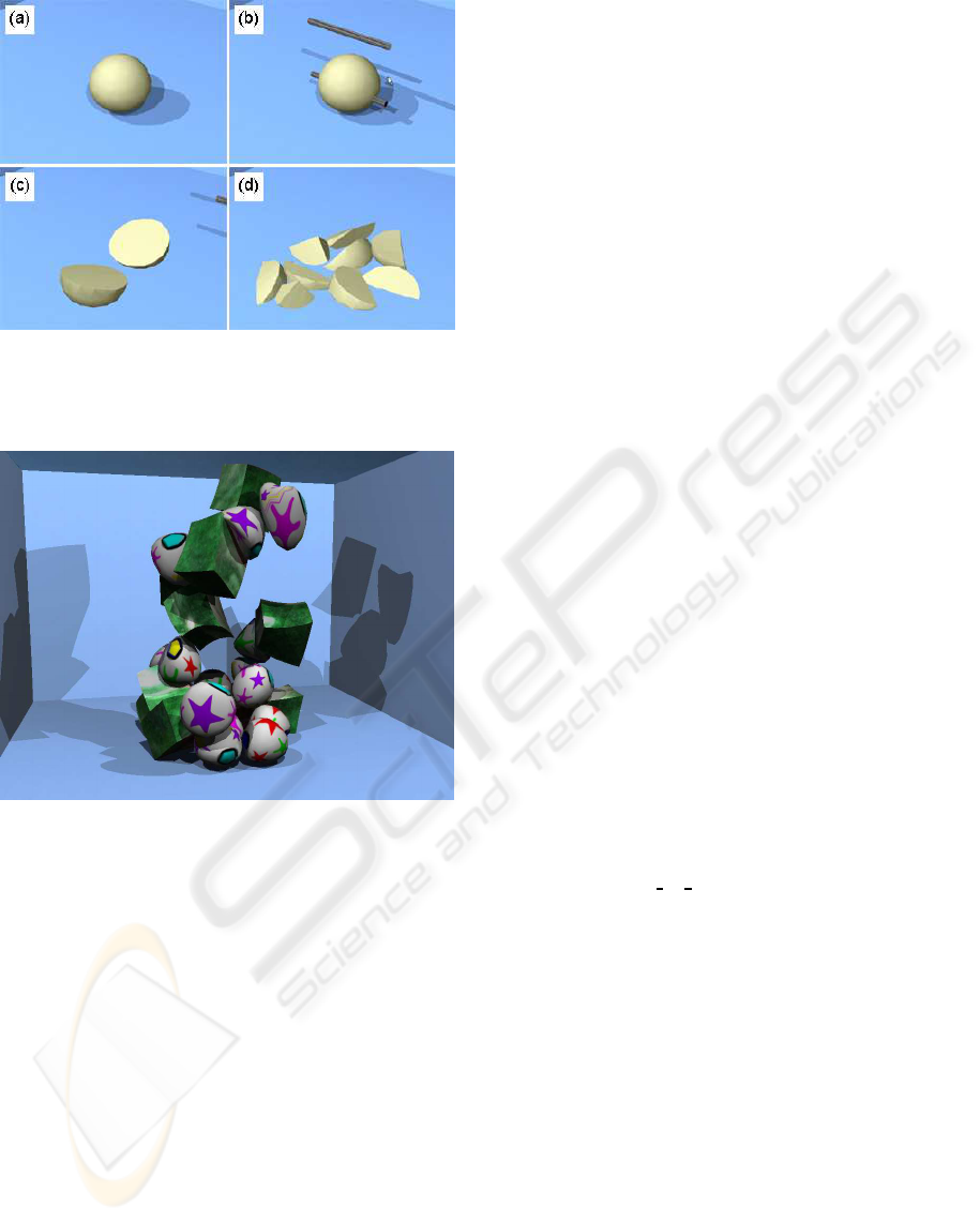
Figure 7: Cutting an object: (a) during cut, (b) immediately
after cut, (c) two resulting halves have rolled apart, (d) after
further cuts.
Figure 8: Large scale simulation of deformable objects.
ronment significantly more enjoyable and immersive
than a comparable rigid body physics environment.
Disadvantages include that simulating local de-
formations requires division of the object into fine
grained clusters, which can be inefficient. Precise
cluster divisions can also be difficult to specify. For
large scale objects and scenes, efficiency improve-
ments are necessary. Finally, the cut operation does
not support partial cuts or incisions, which would be
useful for virtual surgery applications or games.
In summary, we believe that the techniques im-
plemented have promising potential as applied to a
virtual surgery simulator, games, or any other envi-
ronment where speed and immersive interactions are
required but physical accuracy is not.
8 FUTURE WORK
One major problem limiting meshless deformation’s
use in some applications is the lack of robust local
deformation. One avenue of investigation might be to
integrate a mass-spring system, which is usually dis-
abled, but where user picks activate mass-spring be-
haviour in the pick’s local region. Mass-spring areas
around a partial cut or incision could similarly be acti-
vated. For larger cuts, but not complete severances, a
method of dynamically partitioning new clusters may
be possible that would allow “flapping” behaviour,
similar to a tennis ball nearly cut in half with both
halves “talking” like a mouth.
REFERENCES
Arun, K., Huang, T., and Blostein, S. (1987). Least-squares
fitting of two 3-D point sets. IEEE Transactions on
Pattern Analysis and Machine Intelligence, 9(5):698–
700.
Heidelberger, B., Teschner, M., Keiser, R., Muller, M., and
Gross, M. (2004). Consistent penetration depth esti-
mation for deformable collision response. Proceed-
ings of Vision, Modeling, Visualization VMV04, Stan-
ford, USA, pages 339–346.
Horn, B. (1987). Closed-form solution of absolute orien-
tation using unit quaternions. Journal of the Optical
Society of America A, 4(4):629–642.
M¨uller, M., Heidelberger, B., Teschner, M., and Gross, M.
(2005). Meshless deformations based on shape match-
ing. ACM Trans. Graph., 24(3):471–478.
Rubin, J. (2006). A framework for interac-
tive and physically realistic cloth simulation.
780 project report, University of Auckland.
http://www.cs.auckland.ac.nz/˜burkhard
/Reports/2005
SS JonathanRubin.pdf.
Smith, R. (2006). Open Dynamics Engine home page.
http://www.ode.org
.
Teschner, M., Heidelberger, B., Mueller, M., Pomeranets,
D., and Gross, M. (2003). Optimized spatial hashing
for collision detection of deformable objects.
Teschner, M., Heidelberger, B., Muller, M., and Gross, M.
(2004a). A versatile and robust model for geometri-
cally complex deformable solids. Computer Graphics
International, 2004. Proceedings, pages 312–319.
Teschner, M., Kimmerle, S., Zachmann, G., Heidelberger,
B., Raghupathi, L., Fuhrmann, A., Cani, M.-P.,
Faure, F., Magnetat-Thalmann, N., and Strasser, W.
(2004b). Collision detection for deformable ob-
jects. In Eurographics State-of-the-Art Report (EG-
STAR), pages 119–139. Eurographics Association,
Eurographics Association.
Umeyama, S. (1991). Least-squares estimation of transfor-
mation parameters between two point patterns. Pat-
tern Analysis and Machine Intelligence, IEEE Trans-
actions on, 13(4):376–380.
IMPROVED MESHLESS DEFORMATION TECHNIQUES FOR REAL-TIME INTERACTIVE COLLABORATIVE
ENVIRONMENTS
161
