
SAFETY VALIDATION OF AUTOMATION SYSTEMS:
APPLICATION FOR TEACHING OF DISCRETE EVENT
SYSTEM CONTROL
Pascale Marange, François Gellot and Bernard Riera
Centre de Recherche en STIC - UFR des Sciences Exactes et Naturelles
Université de Reims Champagne-Ardenne, Moulin de la Housse, BP 1039, 51687 REIMS Cedex 2
Keywords: Discrete event systems, Validation, Control, Functional identification, Learning.
Abstract: We propose in this paper, to introduce a method to validate logic controller programs adapted to the
teaching of Discrete Event Systems. The use of real systems for teaching raises two problems. The first one
concerns the security of human beings (students and teachers) and materials. The second problem is the
necessity to be able to detect possible errors done by students and to bring an explanation. We propose a
method to define a level of system abstraction, to validate the student’s control by the mean of a validation
filter placed between the plant and the controller. The specifications contained in the filter make it possible
to detect errors and to generate an explanation automatically. We applied this method to an original project
where it was proposed to 7 year-old children, to discover automation, by programming a tablets packaging
system.
1 INTRODUCTION
The implementation of a control in a PLC
(Programmable Logic Controller) raises necessarily
validation problems: “Is the running (plant: PO and
control part PC) safe?”; “Is the specification
respected?”, and if it is not the case, “Which control
errors have been done?”… Our research aims at
ensuring that the control is valid with respect to the
safety and running technical system requirements.
For that, we propose to set up a module which
validates on line the logic controller program. At
each evolution of the system (PO and PC), the
validation module authorizes or not the outputs sent
from the PC to PO. This work finds an interest in the
field of remote maintenance as well as education.
The paper focuses on the last point. We are
interested in the problem of the control validation
carried out by students in automatic-control during
work practise in the field of the Discrete Event
System (DES) and the PLC.
The teaching of automatic control in broad sense
requires the transfer of knowing and know-how to
learners. Know-how concerns for instance the use
and the programming of PLC by means of software
respecting standards like IEC 1131.3. The
acquisition of this technical know-how requires
practical work in specialized and expensive rooms
including PLC and simplified manufacturing
systems which are a replica on a reduced scale of
real systems found in the industry. The use of PLC
raises two problems: safety and explanations.
Indeed, if a programming error occurs, safety has to
be guarantee for materials as well as human
operators being around and explanation has to be
given about the error and its effects on the system.
The suggested solution in this paper is articulated
around a validation filter defined by means of safety
and liveness constraints. The first guarantee the
system safety by prohibiting any evolution being
able to deteriorate it. The second make sure that the
suggested control is coherent with the running
specification (defined in our case by the teacher). It
is important to note that the constraints definition is
related to the possibility of learner’s authorized
actions (i.e. errors done by learners depend on the
possibilities that he has to act on PO). It is very
interesting in the pedagogy field, to propose various
actions levels related to various abstraction levels.
To achieve this goal, the constraints are defined in
reference to a PO functional identification which
makes it possible to fix the abstraction or granularity
degree chosen by the teacher. The use of constraints
makes possible to supply explanatory capacities to
the validation tool. That makes it possible to
guarantee an efficient Human Machine dialogue.
111
Marange P., Gellot F. and Riera B. (2007).
SAFETY VALIDATION OF AUTOMATION SYSTEMS: APPLICATION FOR TEACHING OF DISCRETE EVENT SYSTEM CONTROL.
In Proceedings of the Fourth International Conference on Informatics in Control, Automation and Robotics, pages 111-116
DOI: 10.5220/0001652101110116
Copyright
c
SciTePress

In a first part, the suggested approach of
validation is presented in a general way. This one is
thus based on a functional identification of the
system. The functional model obtained is used to
define the selected abstraction degree. The writing
of the constraints is based on an original
classification which distinguishes the constraints not
only according to their type (safety and liveness) but
also according to their intrinsic characteristic
(combinative or sequential). This classification is the
object of second part. In a third part of the paper, the
approach is applied to a concrete example where we
propose to “young novice” engineers to control a
packaging system.
2 VALIDATION APPROACH
Work in the field of the automatic control validation
aims to insure that mathematical properties are
respected by model (Canet, 2001), (Lampérière and
al, 2000). The work undertaken within the
framework of tool UPPAAL (Behramm and al,
2004) defines three types of properties: attainability,
safety and liveness. We chose to use the safety
constraints: what the system should not do, and
liveness constraints: what the system should do
according to the running specification. The
validation can be considered off line or on line. In
the first case, the control is completely validated
before being sent to the PO (Machado, 2006).
Within this framework, we proposed an off line
approach (Tajer and al., 2006) based on the
Ramadge Wonham supervisory control theory
(Womham and Ramadge, 1987) and the synthesis
algorithm by Kumar (Kumar, 1991). The suggested
approach makes it possible to guarantee that the
control behaviour is safe, deterministic and without
deadlocks. However, it presents several
disadvantages: the combinatorial explosion, the
difficulty to give a comprehensible explanation to
learner. So, we directed our work towards an on line
approach of control validation.
The idea is to inhibit the evolutions which can lead
the system to a situation of deterioration, of setting
in danger of the operators or which does not respect
running specification. Cruette’s work (Cruette,
1991) for the monitoring of automation systems
proposes to intercalate a filter between the PO and
control. The filter ensures on the one hand coherence
between the output and the expected one, and on the
other hand coherence between the evolution of the
expected PO and that produced. This idea of an
approach on line by filter is taken up partially and
adapted to ensure the control validation i.e. with
each new control evolution, the filter receives in
inputs: the evolution of the outputs (controllable
events Ec: actuators) coming from the control
designed by the student as well as the evolutions of
the inputs (uncontrollable events Euc: sensors) of
PO. In the same time that the command execution,
the validation filter authorize or not the new
evolution. For that, the filter contains the safety and
liveness constraints and according to the sensor and
actuators information, it tests the constraints. If all
constraints are true, the evolution is authorized and
the control continues. If not, the evolution is
prohibited and the system is stopped.
2.1 Functional Identification
The suggested approach is based on a hierarchical
functional identification of the system. The first idea
consists in using the functional decomposition to
determine the authorized student’s actions. Indeed, it
seems us that for a beginner for example his possible
actions on PO must be reduced. The second idea
deals with a constraints definition on two levels:
One on the low level (sensor actuator level) to
ensure the safety and the other based on the
functional decomposition to detect programming
errors and to generate an explanation (high level).
That means that the constraints will be defined
starting from the functions that learner is allowed to
implement.
Fi
C
a
C
d
↑Fi ↓Fi
Action : ∑{Ec}
Procedure (controlled
or automatic)
Figure 1: Definition of « Function » notion.
To identify the system functions, of the methods
as SADT (I.G.L technology, 1989), MERISE
(Tardieu and al., 2000) make it possible to cut out
the system in functions and under functions
according to a downward hierarchical approach.
Within the framework of the suggested approach, it
is necessary for each function identified to know the
activation conditions Ca (initial conditions), the
deactivation conditions Cd (function goal) and its
execution mode (controlled or automatic) (figure
1).
The procedure will make possible to define an
additional degree of freedom in the control, for a
level of functional decomposition fixed. In the case
of the controlled mode, the learner must manage the
activation and the deactivation of a function, when
the conditions become true. On the other hand, in the
ICINCO 2007 - International Conference on Informatics in Control, Automation and Robotics
112

case of the automatic mode, student must only
activate the function which is deactivated when the
deactivation conditions are true.
The model of figure
1 shows that each function
can be activated (
↑
Fi) or be deactivated (
↓
Fi). The
action of activation is always controllable. On the
other hand, the action of deactivation is controllable
when the execution is in controlled mode and
uncontrollable when the procedure is automatic.
According to the selected granularity (the degree of
decomposition), the term “function” represents the
control (activation, deactivation) of a whole station
as well as a simple actuator. The decomposition or
abstraction degree will allow a teaching at various
levels and adapted to the learner knowledge.
2.2 Use in the Teaching
In the framework of the DES teaching, the level of
granularity will allow to propose more or less
difficult and evolutionary exercises adapted to the
training level. The granularity is at the responsibility
of the teacher who must adapt this one to the level of
learning. Indeed, if teaching is addressed to:
a novice, description can stop at the
functional level (high level) of the plant. It is the
teacher who gives the control of each function and
learner has to provide the chronology.
a beginner, with regard to the difficulty of
each function, he can control several of them (high
level) and program completely the others (low
level). It is the teacher who has to decide which
functions are automated.
an advanced student is able to control the
system as a whole and thus he acts on the plant at
the low level.
Once the teacher has defined the granularity of
the system, he can choose according to two
procedures already presented.
The validation approach must make possible to
ensure the safety and the respect of the running
specification. For that we propose to set up safety
and liveness constraints which are defined starting
from the functional identification of the procedure.
The suggested method requires to make some
assumptions and to specify certain terms. The
functional identification gives a finished set of
functions and the functions are independent to each
other. Moreover, it is supposed that it is not possible
to have multiple activation of the same function (i.e.
an only instance at a time).
On the low level, the description of a control
model can be made by means of the input/outputs
vector. The vector value at time t corresponds to the
current state of the system. By analogy, on a fixed
level of functional decomposition, it is possible to
define a vector of state corresponding to the input-
outputs of the function. The inputs are then the
activation and deactivation conditions of the
function and the outputs the actions related to the
function represent.
3 VALIDATION FILTER
To ensure the safety and the correct running of the
system, the validation filter uses some specifications
to detect and to bring an automatic explanation. The
definition of the specifications is not easy. Thus, we
propose to carry out a distinction on their role
(safety or liveness) and on their intrinsic
characteristics (combinational, sequential, dynamic
or static).
3.1 Safety Validation of System
The safety constraints characterize what the system
should not do. It seems us important to place the
safety constraints at the sensors - actuators level.
Three types of safety constraint are defined.
3.1.1 Static Safety Constraint
The static safety constraints express physical and
technical impossibilities of the system elements. The
static safety constraints depend only on the
controllable events. The Syntax is: C = Ec
i
∧ Ec
j
.
For example, if the event Ec
1
cannot be carried out
at the same time as the event Ec
2
, then: Ec
1
∧
Ec
2
=0.
3.1.2 Dynamic Safety Constraint
The dynamic safety constraints relate to the
occurrence of an event which is not compatible with
an other event. The event corresponds either at the
activation of controllable event (
↑
Ec), or with the
validation of the deactivation condition (
↑
Euc):
In the first case, the constraint is written in
the following way: Euc
i
∧
↑
Ec
j
= 0. Indeed, if the
deactivation conditions are present, the sending of
the associated controllable event is prohibited.
In the second case, the constraint is written:
Ec
j
∧
↑
Euc
i
= 0. Indeed, as soon as the deactivation
conditions are present, the actuator must be
deactivated.
The safety constraints make it possible to protect
the system against deteriorations. For these
constraints, the validation filter can be placed in the
SAFETY VALIDATION OF AUTOMATION SYSTEMS : APPLICATION FOR TEACHING OF DISCRETE EVENT
SYSTEM CONTROL
113

control part (PLC). The validation filter prohibits the
sending of a command if this one of the safety
constraints does not respect constraints.
The definition of the safety constraints is re-used
at the functional level, in a redundant way to bring
an automatic explanation to the learner’s errors:
If functions cannot be activated at the same
time: F
i
∧
F
j
= 0
If the deactivation condition of a function is
present, the sending of the function is prohibited:
Cd_F
i
∧
↑
F
i
= 0.
If the activation condition is not true, the
function cannot always be activated: /Ca_F
i
∧↑
F
i
=0.
As soon as the deactivation condition is
true, the function must be deactivated: F
i
∧↑
Cd_F
i
=0
It is necessary now to determine if functioning is
correct compared to the running specification. For
that it is proposed to set up liveness constraints.
3.2 Liveness Validation
The control validation compared to functioning,
goes through by the definition of liveness constraints
(what the system must do compared to the running
specification). Contrary to the safety constraints, the
liveness constraints are placed only at the functional
level. Two types of constraints are defined:
combinational and sequential liveness constraints.
3.2.1 Combinational Liveness Constraints
The combinational liveness constraints allow
activation or deactivation when the conditions are
present. The combinational liveness constraints are
defined in a similar way to the dynamic safety
constraints. For example the function F
i
can occur
only under the condition Ca
i
:
↑
F
i
∧
Ca
i
= 1 or the
function F
1
must be deactivated when the condition
Cd
i
is true:
↓
F
i
∧
Cd
i
= 1.
3.2.2 Sequential Liveness Constraints
By the sequential liveness constraints, the function
sequencing is described. The idea is thus to represent
the sequence described by the running specification
without to describe one unique behaviour. The
logical equations do not make it possible to manage
this sequential aspect simply.
The possibility to carry out a function compared
to the expected behaviour depends on the system
situation, i.e.: the functions which have been carried
out. We point out that the possibility to carry out a
function compared to the system state is expressed
by the combinational liveness constraints. To take
into account the functions sequencing, for each
function, we define the deactivation conditions and
the functions which had to be fulfilled. In the same
way, the function execution will influence the future
behaviours and thus the functions which will not be
realizable any more. To express the functioning
sequencing, it is proposed to draw up a table with
information: the deactivation conditions, the
functions which had to precede, the functions which
will not be realizable any more. For each function,
we define Grafcet with the states {not carried out, in
execution, carried out}. Grafcet evolves at the same
time as the command. Grafcet makes it possible to
know the functions authorized or not compared to at
functioning awaited.
According to the functional identification, if the
functions are carried out the ones after the others or
in parallel, all the constraints will not be defined.
Indeed, if the execution is in automatic mode, the
function is deactivated automatically when the
deactivation conditions are present. In this case, it is
not necessary to define the dynamic safety
constraints on the uncontrollable events.
3.3 Use in the DES Teaching
Within the framework of teaching, we can propose a
tool that ensures in priority the system and operators
safety, thanks to the definition of the safety
constraints on the sensor actuator level. The
definition at the functional level, of the safety
constraints makes it possible to generate simply and
automatically explanations related to an error. The
detection and the management of the errors will be
done in a simple way by the constraint validation or
not. During the validation stage, three different cases
are possible:
All the specifications are validated, the
validation filter allows the sending of the
controllable event to the plant
One or more safety specifications or
constraints are not respected. In this case, the
validation filter does not authorize the controllable
event and informs the student on the specifications
which are not respected.
One or more liveness constraints are not
respected. That means that the running specifications
are not all respected. In this case, if all safety
constraints are OK, controllable events can be
accepted because there is no risk for the system. The
explanation generation associated with an error, is
also done in a simple way. Indeed, the distinction
that we could establish in the two previous parts for
the safety and liveness constraints enables us to find
an automatic explanation to the non respect. The
safety constraints must be validated permanently
ICINCO 2007 - International Conference on Informatics in Control, Automation and Robotics
114

independently to each other. If there is one or more
safety constraint violation that means:
For the static safety constraints, the control
wants to send an order whereas the system is making
the contrary order.
For the dynamic safety constraints on an
uncontrollable event, the non deactivation of an
order whereas a sensor indicates that it should be
deactivated.
For the dynamic safety constraints on a
controllable event, either the associated sensor with
this action is already in the wished state, or the
evolution of this order is impossible compared to the
system conditions.
For the combinational liveness constraints, we
use the same approach as previously, if the
constraint equation is not respected, that means that
the control wants to send an order whereas it is not
the waited behaviour. The automatic generation of
explanation for the sequential liveness constraints is
more difficult, because they are not defined by
logical equations. We can go up the evolution which
has just occurred by the mean of the active states in
the different Grafcets. With this information, the
teacher should find by himself an explanation.
4 APPLICATION
The idea was to collaborate (Riera et al., 2005) with
a teacher of “primary” school. We wanted to allow
the child to discover and to control really the system
by programming his/her own sequence.
Station 5
Station 1
Distribution of green tablets
Station 2
installation of a large stoppe
r
Station 3
Distribution of white tablets
Station 4
installation of a small stopper
and evacuation
Figure 2: Productis Machine.
The system used for this project is the
“Productis” machine. This system allows the
packaging of tablets (figure 2). The system is
composed of 5 stations and a conveyor: Station 1:
distribution of green tablets by counting, Station 2:
installation of a large stopper on the large tube,
Station 3: distribution of white tablets by counting,
Station 4: installation of a small stopper on the small
tube and/or evacuation of the tube in a box, and
Station 5: Feeding of the system. In order to make
the activity of control design funny for the child, we
propose the following original scenario. The
instructions to use the machine have been lost. So, it
is impossible for us to manufacture drug to heal sick
fairies. Children have to find the running of the
machine in order to manufacture specific drug. We
have to adapt the vocabulary used to describe the
system, at the age of the children. The activity is
proposed with children, they know to rebuild a
history according to a chronology. The children
must create a sequence of functions to manufacture a
tablets bottle. The functions execution is done in
automatic mode. The child sends the order to
activate a function which is automatically
deactivated when the deactivation conditions are
true. The functions are entirely carried out the one
after the others. For this activity, we decided that the
simultaneous sending of functions was impossible.
Only one pallet circulates in the system in order to
simplify the system comprehension. After functional
identification of the system, we selected 20
functions could be programmed by children. For
that, we analysed the system by stations. The pallet
is manually loaded (station 5). The child presses on
a button to release the pallet. We choose to describe
only the station 4: positioning of a small stopper and
evacuation. This station is composed of a prehensor,
i.e. two cylinders (one for the vertical movement and
one for the horizontal movement), and a vacuum
system. To install a stopper, it is necessary to
position the cylinder to the top, go down, take the
cap, go up, advance the cylinder, go down and
release the aspiration. In order to avoid
synchronization in the control program designed by
children, functions “put the stopper” have been
divided into respectively two functions: “Take the
stopper” and “Loosen the stopper”. With regard to
the functional analysis, children also have to
program the control of the ejection by the mean of
the gripper. In this part, only the constraints at the
functional level of station 4 will be developed and
explained:
Static safety constraints: it is not necessary
because the learner cannot send several actions
simultaneously.
Dynamic safety constraints on a
controllable event:
/up
4
∧
(
↑
Go_out
∨↑
Go_in) =0;
↑
Close
4
∧
/ (down
4
∧ in
4
) = 0
Dynamic safety constraints on
uncontrollable events are not necessary because
learner must not deactivate the function. The
execution of the functions is in automatic mode
Combinational liveness constraints:
• the aspiration of the stopper is authorized
only in the position : down and in (in the same
way for the gripper)
SAFETY VALIDATION OF AUTOMATION SYSTEMS : APPLICATION FOR TEACHING OF DISCRETE EVENT
SYSTEM CONTROL
115
↑
Take
4
∧
(down
4
∧ in
4
) =1;
↑
Close_gripper4
∧
(down
4
∧ in
4
)=1
• the ejection of stopper can only be done in
the position : down and out
↑
Loosen
4
∧
(down
4
∧
out
4
) =1;
↑
Open_gripper4
∧
(down
4
∧
out
4
)=1
Sequential liveness constraints have to
ensure that: the bottle is closed before carrying out
the function of bottle evacuation.
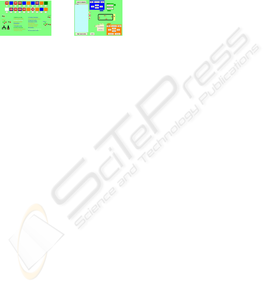
a)
“Step by step” mode b) Sequence mode
Figure 3: Interfaces.
The activity with the children proceeds in two
parts. In the first, the child has at his disposal an
interface (figure
3.a) with 20 buttons. The 20 buttons
represent the 20 functions of the system. In this
activity, the child has to understand the role of each
button. For that, the child presses a button of the
interface. Thus, the child causes the movement or
the movements corresponding to the function on the
machine and he has to associate a function to a
button. According to the state of the system, all the
buttons are not activated. For example, if the
cylinder of station 4 is in position “in”, the button
“To Go_in cylinder” of station 4 cannot be pressed.
After having understood the role of each button, the
child can perform the second part of work (second
interface). During the second activity (figure
3.b),
the child programs his own sequence of functions to
build a bottle of drugs. The sequence execution is
validated on line. Hence, if the constraints are
respected, the function having to be performed is
performed, and the sequence can continue. If not, the
validation system informs the child what are the
constraints which are not respected.
5 CONCLUSIONS
We bring in this article some answers to the
problems raised by the provision of automated
material, for the teaching of automated systems
control. For that, a validation approach on line by
filter was proposed. This approach makes it possible
to filter the evolutions which are dangerous for the
system, or which do not answer the running
specifications. The proposed approach can generate
automatically an explanation. For that, the validation
filter uses safety and liveness constraints of which
definitions have been proposed. The modelling of
sequential liveness constraints is a point that has to
be developed, particularly to be able to generate
automatic explanations. The proposed modelling of
sequential liveness constraints has been designed to
manage only one product in the manufacturing
system. This extension has to be thought of doing. In
addition, we also must improve the error explanation
stage for the teacher. It seems possible, for example,
at the same time as the system evolution (real plant)
to use a simulated plant where the errors effects are
displayed. In the simulated plant, learner could
observe the consequences of his error.
REFERENCES
Behramm G., David A., Larsen K.G., A tutorial on
UPPAAL, novembre 2004
Canet G., Vérification automatique de programmes écrits
dans les langages IL et ST de la norme IEC, thèse de
doctorat, Ecole Normale Supérieur de Cachan.
December 2001
Cruette D., Méthodologie de conception des systèmes
complexes a événements discrets : application à la
conception et à la validation hiérarchisée de la
commande de cellules flexibles de production dans
l’industrie manufacturière, Thèse de doctorat,
Université de Lille, 1991
International Electrotechnical Commission, Preparation of
function charts for control systems, International
Standard, CEI/IEC 848, 1991 (revised version).
I.G.L. Technology, SADT, un langage pour communiquer,
Eyrolles, Paris, 1989.
Kumar R., Supervisory Synthesis Techniques for Discrete
Event Dynamical Systems, Thesis for Ph. D. Degree,
Université du Texas, 1991.
Lampérière S., Lesage J.J, Formal verification of the
sequential part of PLC programs, Proc. Of 5th IFAC
Wodes, pp 247-254, Ghent, Belgium, August 2000
Machado, Influence de la prise en compte d’un modèle de
processus en vérification formelle des systèmes à
événements discrets, Thèse de doctorat de l’école
normale supérieure de Cachan et de l’université de
Minho (Portugal), juin 2006
Riera B., Gellot F., Marangé P., Chemla J-P., Sayed
Mouchawed M., Un projet original en commande et
supervision des systèmes automatisés : Des enfants de
5ans au secours d’animaux malades !, CETSIS’05,
Nancy, France, 25-27 octobre 2005
Tajer A., Marangé P., Gellot F., Carré Ménétrier V.,
Synthèse d’une commande supervisée à base de
contraintes logiques, revue électronique e-STA , 2006
Tardieu H., A. Rochfeld, R. Colletti, La méthode Merise –
Principes et outils, Edition d’organisation, 2000
Wonham W. M., Ramadge P.J., On the supremal
controllable sublanguage of has given language, SIAM
J Control Optimization, flight 25, n°3, p.637-659,
1987
ICINCO 2007 - International Conference on Informatics in Control, Automation and Robotics
116
