
A FEATURE DETECTION ALGORITHM FOR AUTONOMOUS
CAMERA CALIBRATION
Kyung Min Han and Guilherme N. DeSouza
University of missouri-columbia, Columbia, Missouri, USA
Keywords: Autonomous camera calibration, Automatic feature detection, Line and Corner detection.
Abstract: This paper presents an adaptive and robust algorithm for automatic corner detection. Ordinary camera
calibration methods require that a set of feature points – usually, corner points of a chessboard type of
pattern – be presented to the camera in a controlled manner. On the other hand, the proposed approach
automatically locates the feature points even in the presence of cluttered background, change in
illumination, arbitrary poses of the pattern, etc. As the results demonstrate, the proposed technique is much
more appropriate to automatic camera calibration than other existing methods.
1 INTRODUCTION
In any automatic camera calibration procedure, one
must devise an algorithm that can – without human
intervention – accurately and reliably: 1) identify
special features in a set of images; and 2) correspond
the features over the image set so they can be used
as calibration points. In order to accomplish that,
such algorithm must be able not only to detect as
many features as possible, but it also needs to
determine the pixel coordinates of the features in a
consistent manner throughout the image set.
The existing algorithms for camera calibration
(Zhang 1998) (
Huang and Boufama 2006) (Weng
1992) (Tsai 1987) rely mainly on detecting corners
on a chessboard-like calibration pattern, or the
centroid of circles in a dotted calibration pattern
(Kim and Kwon 2001). Other approaches (Chen
2005) (
Baker and Aloimonos 2000) try to avoid using
such patterns, but despite the method used, a set of
corresponding points in multiple images must
always be obtained
The main problem with some of these
approaches (Zhang 1998) (
Huang and Boufama 2006)
(Weng 1992) (Tsai 1987) is that, while a large
number of feature points can be easily obtained, the
correspondences between features can be
compromised by perspective distortions, changes in
illumination, etc. That is, due to, for example, the
relative pose of the pattern with respect to the
illumination source, the same corner point found in
one image of the set may be detected by the
algorithm a few pixels off from its actual location.
Moreover, many of the algorithms above mentioned
require that the user define the location and/or size
of a search window where the algorithm will look
for the feature points (Harris and Stephen 1988). In
an automatic calibration procedure, where the
pattern may be presented to the camera at different
depths (scale), a restriction on the size of the
window would obviously render the algorithm
useless.
In this paper, we present an algorithm for
automatic camera calibration that relies on a line
detection method (Hough Transforms) to find the
feature points. In our system, a sequence of images
is captured by the camera(s) while a calibration
pattern is arbitrarily moved in front of the camera(s).
The proposed algorithm automatically searches
for feature points on the pattern that will be used for
calibration. As in the above algorithms, the feature
points are the corners of the squares in a chessboard
pattern, but unlike in these algorithms, the points are
now defined by the intersection of the many vertical
and horizontal lines running over the edge of the
squares.
That is, instead of looking for localized feature
discontinuities inside a small search window, as in
traditional corner detection algorithms, our
algorithm uses a global property of the pattern to
localize the corner more accurately.
Our algorithm is very robust to cluttered
background and it can reject points outside the
perimeter of the pattern even if the background
presents distinctive features similar to the ones in the
286
Min Han K. and N. DeSouza G. (2007).
A FEATURE DETECTION ALGORITHM FOR AUTONOMOUS CAMERA CALIBRATION.
In Proceedings of the Fourth International Conference on Informatics in Control, Automation and Robotics, pages 286-291
DOI: 10.5220/0001631902860291
Copyright
c
SciTePress
pattern. Also, due to the use of global rather than
local features, the calculated pixel coordinates of the
corners are significatively more accurate than those
obtained using corner detection algorithms, leading
to a much more accurate final camera calibration.
2 PROPOSED ALGORITHM
The proposed algorithm consists of two main parts.
In the first stage, the algorithm searches for visible
features in a set of images of the calibration pattern.
Once the features are located, the algorithm
determines the feature correspondence between
images. The output of this stage of the algorithm is a
list of world coordinates of the features and their
corresponding pixel coordinates in the various
images used.
The second stage of the algorithm implements
a camera calibration procedure based on Zhang’s
algorithm (Zhang 1998). This part of the algorithm
is outside the scope of this paper and will not be
covered here. In the next section we will present the
first stage of the algorithm in more detail.
2.1 Feature Detection
Our algorithm uses a chess board pattern as depicted
in Figure 1. The pattern contains one gray square in
the middle, while all others are black. The reason for
this special square is for the algorithm to be able to
locate the origin of the pixel coordinate system and
to assign coordinates to the features automatically.
The main constrain imposed to this algorithm is to
detect a significant number of points so that the
calibration error can be minimized.
Through experimentation, it was determined
that at least 150 points out a total of 196 points of
the pattern must be detected for good calibration.
Thus, in the ideal case, the algorithm must find a
total of 28 lines – i.e. 14 horizontal lines and 14
vertical lines. The corner points are defined by the
intersections of the two sets of fourteen lines.
2.2 The Hough Transform
The Hough Transform (Hough 1966) is one of the
most popular methods for extracting lines from
images. It is used to transform u-v pixel coordinates
of points on a line into the parameters of such line.
That is, consider, for example, the equation of a
straight line in the image space,
cumv
+
∗
= .
Where m is the slope and c is the vertical intercept.
This equation can be represented by a single point in
the parametric space. Since the actual m and c of
such a line is initially unknown, the Hough
transformation can be performed by accumulating
“votes” from every point (u, v) on the line. That is,
every point (u, v) will vote for all points of the line
vumc
−
∗
=
in the m-c space. Since all u,v-points
on the same line will vote for a common m-c point in
this parametric space, one point will accumulate
more votes than any other point – which can be used
to detect the original line in the image. Due to noise,
the Hough algorithm could detect more than one set
of parameters for a single line in the image. One of
the key points in the proposed algorithm is to
eliminate those erroneous detections. For that, the
proposed algorithm must adapt to different situation,
such as the orientation and size of the pattern,
different illumination conditions, etc.
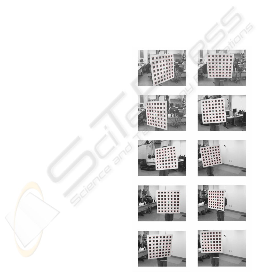
Figure 1: A sample of the typical poses of the pattern
presented to the camera for calibration.
FEATURE DETECTION ALGORITHM FOR AUTONOMOUS CAMERA CALIBRATION
287
2.3 Detailed Algorithm
The first step of the algorithm is an edge detection.
Then the Hough transformation is applied to all
points on the edge images. Next, as we explained
earlier, our algorithm searches for the intersections
of all lines obtained from the Hough transform. At
that point, due to noise in the images, two erroneous
situations may arise. First, spurious lines outside the
pattern may be detected. Second, multiple lines can
be detected for a single line in the pattern.
The first erroneous case is handled by the
algorithm using a set of simple but comprehensive
heuristics, such as: 1) the slope of any line must be
similar to the slope of thirteen other mostly vertical
or horizontal lines; 2) the distance between lines
must be consistent among the two sets of lines
(vertical and horizontal); and 3) the number of
expected lines.
It is important to mention here that the two sets
of lines, vertical and horizontal, are not necessarily
as so. That is, the algorithm allows for the pattern to
be presented in any orientation – as it is
demonstrated in Figure 1. The use of the term
“vertical” and “horizontal” above is just for clarity
of the explanation.
The second erroneous detection is illustrated by
Figure 3(b). As it is shown in this figure, the Hough
transform may detect multiple lines for a single line
on the pattern. That results in multiple intersections
for a single corner. In order to handle these cases,
the algorithm first groups these points by their
Euclidean distances. Once the clustering is obtained,
the algorithm uses some stochastic criteria to
eliminate erroneously detected corners. For example,
the algorithm eliminates outliers farther than ½
standard deviations from the mean and recalculates
the pixel coordinate of the corner afterwards. Once
the algorithm processes the steps above, it then
calculates the mean of each cluster. These means
represent the corner points of the pattern. A
predefined order of the corners allows us to search
and label the corner points starting from the center
of the pattern. For this reason, finding the exact
position of the center square (gray square) is a
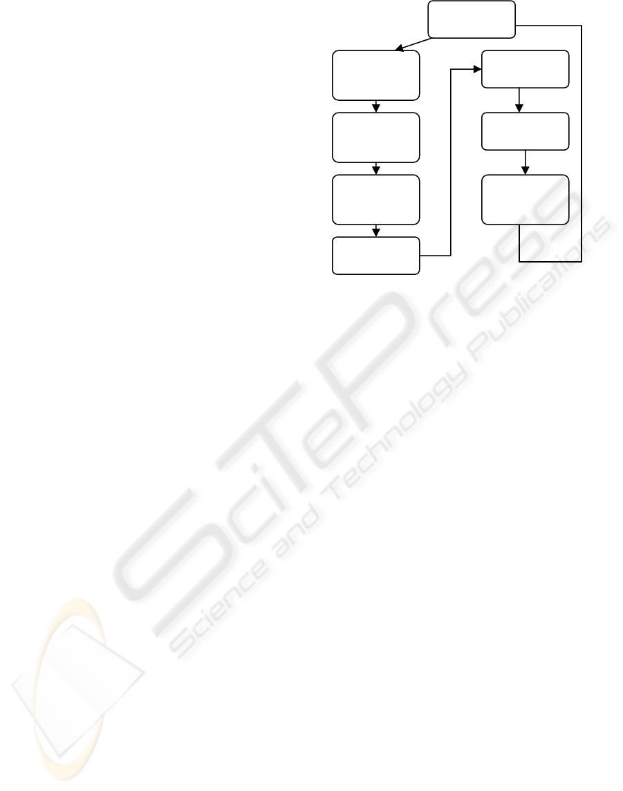
critical step of the proposed algorithm. Figure 2
shows a brief flow chart of the proposed algorithm
Figure 2: A brief flow chart of the proposed algorithm.
3 RESULTS
In this section we detailed two of the tests performed
to validate our algorithm. In the first test, we
compared a corner detection algorithm found in the
literature (Harris and Stephens 1988) against our
proposed method. In the second test, we present the
final accuracy in 3D reconstruction after employing
our algorithm to calibrate a multi-stereo rig
composed of 6 cameras.
3.1 Corner Detection
In order to compare our method with a traditional
corner detection algorithm, we collected 196 points
in one image of the pattern at a typical position and
orientation (Figure 4).
Apply Hough
transfrom
Find
intersection
points
Cluster
intersection
points
Eliminate
outliers
Find cluster’s
mean
Label corner
points
Save
correspond
corner points
Capture an
image
ICINCO 2007 - International Conference on Informatics in Control, Automation and Robotics
288
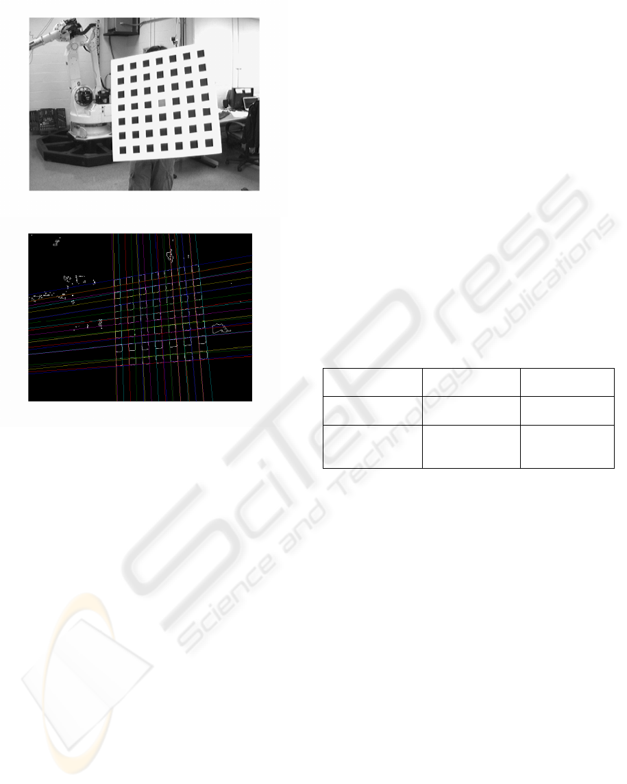
Figure 3: (a) Original image, (b) Detected Lines.
As the red circles in the figure depicts, the
corner detection algorithm finds many spurious
points in the image outside the boundaries of the
pattern. As explained earlier, these types of
algorithms require the delineation of regions of
interests for their proper operation. Since our goal is
to use the algorithm autonomously, such delineation
must not be performed, which leads to a bad
performance of the corner detection.
On the other hand, most of the points detected
by our proposed algorithm lie within the pattern
boundaries. However, even if one or more points
happen to fall outside the pattern boundary – due to
erroneous extraction of lines outside the pattern –
the second stage of the algorithm can still reject
those points (as explained in Section 2.3).
As it can be seen in the blown-up images of the
pattern, the corner detection algorithm presents a
very large variance in the actual determination of the
pixel coordinates of the features.
Table 1 presents a quantitative measurement of
the performance of both algorithms regarding this
variation in the position of the corners.
In order to obtain such measurement, we
defined a ground truth by manually clicking on 42
corner points in the image. The so defined ground
truth was then used to compare both algorithms.
As it is demonstrated in Table 1, the proposed
algorithm outperformed the corner detection
algorithm in terms of the distance between the
detected coordinate of the corner and the expected
coordinate of that same corner. That average
distance in the proposed algorithm is less than half
of the distance from the other algorithm. That
difference in performance can lead to a very bad
calibration of the camera, as pointed out earlier.
Another important point to make about the
advantage of the proposed algorithm can be
demonstrated by Figure 1. As that figure shows, our
algorithm is quite robust to changes in pose of the
pattern and background. To validate that point, we
took 100 snapshots of the pattern from 6 different
cameras in our lab. In all cases, the algorithm
detected the feature points in the pattern without any
problems.
Table 1: Distance in pixels between detected features and
ground truth.
Average distance
(in pixels)
Stdrd deviation
(in pixels
)
Proposed
algorithm
0.955 0.7159
Algorithm in
(Harris and
Stephens 1988)
2.324 0.7883
3.2 Result from 3D Reconstruction
52Next, we tested our algorithm by carrying out the
complete calibration of a total of 6 cameras and by
determining the 3D coordinates of a set of arbitrary
points in space using the calibrated camera. That is,
using the calibration matrix obtained using the
proposed algorithm and the pixel coordinates of a set
of predefined points in all 6 cameras, we reconstruct
the spatial coordinates of these points and compared
the calculated values with the real ones. The points
in space were defined by making special marks on a
ruler.
The calibration error was measured by
averaging the result from 20 different snapshots
while holding the ruler. The marks on the ruler were
placed at exactly 50cm apart. Each snapshot is taken
by all 6 cameras, so a total of 120 images were used
for this test. The accuracy of the final calibration
was determined by calculating the distance between
the two marks. Figure 5 illustrates the above
procedure.
FEATURE DETECTION ALGORITHM FOR AUTONOMOUS CAMERA CALIBRATION
289
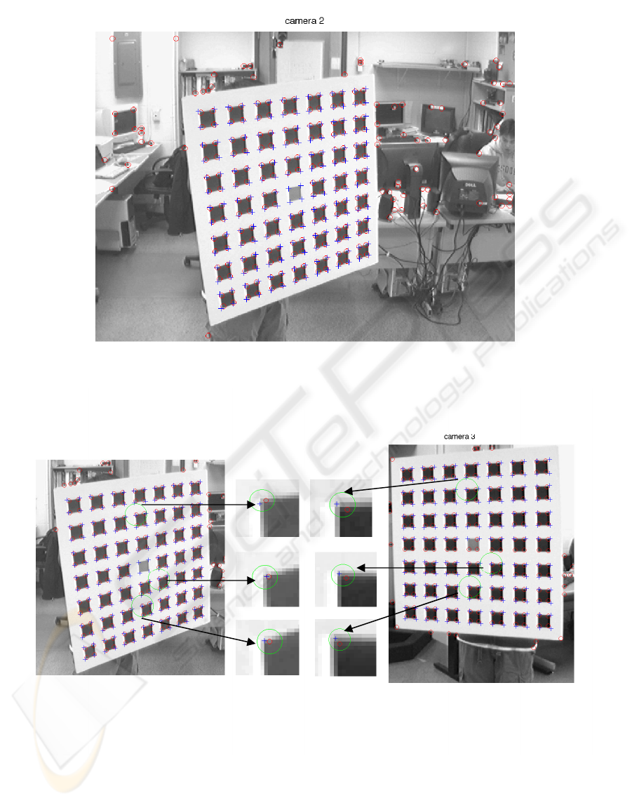
Figure 4: (a) Comparisons between a corner detection algorithm (Harris and Stephens 1988) and the proposed algorithm.
The red circles indicate the result from the corner detection algorithm, while the crosses indicate the output of the proposed
algorithm. (b) Discrepancies of feature points in (Harris and Stephens) corner detection technique.
ICINCO 2007 - International Conference on Informatics in Control, Automation and Robotics
290
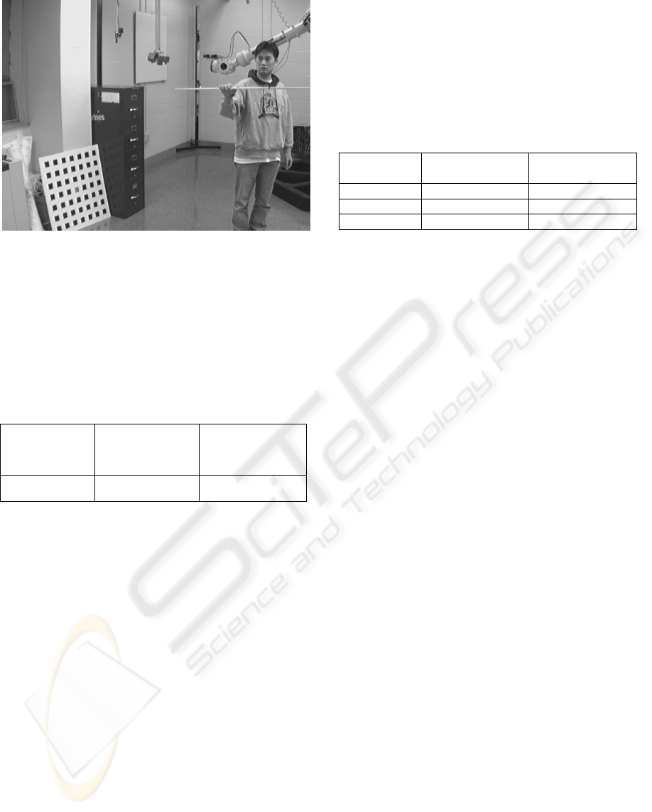
Figure 5: One of the 120 testing images used for 3D
reconstruction.
As can be seen from Table 2, the accuracy in
3D reconstruction is quite reasonable – less than
1.5% of the actual distance. Also, the small standard
deviation shows that the calibration obtained with
our algorithm give a very consistent 3D
reconstruction.
Table 2: Mean distances of 20 positions of the ruler.
The number
of positions of
the ruler
Mean distance
between the two
points (cm)
Error standard
deviation (cm)
20 50.6264 0.2498
4 CONCLUSION
We presented an autonomous feature detection
algorithm using Hough transforms. The proposed
algorithm was compared against other traditional
corner detection algorithms and the results indicate
that not only our algorithm is more consistent
regarding the detection of the feature points, but it is
also more robust with respect to cluttered
backgrounds. Both properties of the algorithm allow
its use in an autonomous camera calibration
procedure – which was the main motivation for this
work.
Finally, the experimental results obtained
demonstrate the superiority of our approach when
compared to other existing algorithms. The proposed
algorithm presented an average error of less than
half of that of a traditional corner detection
algorithm. Also, in terms of the final accuracy in 3D
reconstruction using our algorithm, the results
showed a quite insignificant error – just a few
millimeters. In fact, such small error could be
originated from the pixel quantization used in our
tests. That is, as it is shown in Table 3, the simple
quantization of one or two pixels can lead to
approximately the same error in 3D reconstruction
as the one from our algorithm.
Table 3: Error in 3D reconstruction due to pixel
quantization.
Trial # Error due to 1
pixel off (cm)
Error due to 2
pixel off (cm)
1 0.2130 0.4398
2 0.1576 0.3135
3 0.2420 0.4785
REFERENCES
P.V.C Hough, “Methods and Means for Recognizing
Complex Patterns,” U.S. Patent 069654, 1962
Zhengyou Zhang. “A Flexible New Technique for Camera
Calibration” Microsoft Research Microsoft
corporation, One Microsoft way 1998
Jun-Sik Kim, In-So Kweon, “A New Camera Calibration
Method for Robotic Applications,” Proceedings of the
IEEE, International Conference on Intelligent Robots
and Systems, Oct 29- Nov 03, 2001
Zonglei Huang & Boubakeur Boufama, “A Semi-
automatic Camera Calibration Method for Augmented
Reality,” Proceedings from the 2002 IEEE
International Conference on Systems, Man, and
Cybernetics, vol. 4 no. pp.6,. Oct 2006.
Juyang Weng, Paul Cohen, and Marc Herniou, “Camera
Calibration with Distortion Models and Accuracy
Evaluation,” IEEE Transactions on Pattern Analysis
and Machine Intelligence, vol 14, no. 10, Oct 1992
Roger Y. Tsai. “A versatile camera calibration technique
for high accuracy 3D machine vision metrology using
off-the-shelf TV camera and lense”. IEEE
Transactions on Robotics and Automation, vol. RA-3,
no.4, August 1987
C. Harris and M. J. Stephens, “A combined corner and
edge detector,” Proceedings of the 4th Alvey
Conference, pages 147--152, Manchester, UK, August
1988.
Kuan-Wen Chen, Yi-Ping Hung, and Yong-Sheng Chen,
“On Calibrating a Camera Network using Parabolic
Trajectories of a Bouncing Ball,” Proceedings of the
2nd IEEE international Workshop on VS-PETS,
Beijing, China, October 15-16, 2005
Patrick Baker and Yiannis Aloimonos, “Complete
Calibration of a Multi-camera Network,”
Omnidirectional Vision, 2000, Proceedings, IEEE
Workshop, page 134-141, Jun 12, 2000
Hirotake Yamazoe, Akira Utsumi, and Shinji Abe
“Multiple Camera Calibration with Bundled
Optimization using Silhouette Geometry Constraints,”
ICPR, Hong Kong, China, August 20-24, 2006
FEATURE DETECTION ALGORITHM FOR AUTONOMOUS CAMERA CALIBRATION
291
