
Analysis of Distributed Resource Management in
Wireless LANs that Support Fault Tolerance
Ghassan Kbar
1
and Wathiq Mansoor
2
1
American University in Dubai (AUD), UAE
2
Zayed University, Dubai, UAE
Abstract. Deploying wireless LANs (WLAN) at large scale is mainly affected
by reliability, availability, and performance. These parameters will be a
concern for most of managers who wanted to deploy WLANs. In order to
address these concerns, new radio resource management techniques with fault
tolerance can be used in a new generation of wireless LAN equipment. These
techniques would include distributed dynamic channel assignment, sharing load
among Access Points (AP), and supporting fault tolerance. Changing from the
relatively static radio resource management techniques generally in use today
to dynamic methods has been addressed in previous research article using
centralized management, but it suffer from network availability problem. In
[10] a new distributed management for dynamic channel assignment has been
suggested. In this paper the idea has been extended to support fault tolerance,
which improves the network availability and reliability compared to centralized
management techniques. In addition, it will help in increasing network
capacities and improve its performance especially in large-scale WLANs. The
new system has been analyzed and according to binomial distribution results
showed improvement of network performance compared to static load
distribution.
1 Introduction
WLAN technology is rapidly becoming a crucial component of computer networks
that widely used in the past few years. Wireless LAN technology evolved gradually
during the 1990s, and the IEEE 802.11 standard was adopted in 1997 [1]. Companies
and organizations are investing in wireless networks at a higher rate to take advantage
of mobile, real-time access to information.
Enterprise managers want to deploy wireless networks with several important
qualities. These include; high security, highly reliable and available WLANs with
very little downtime, and high performance. The ideal wireless network is to have
reliability, availability, and performance criteria to be similar of wired enterprise
networks. In addition, it should be possible to deploy wireless networks very quickly
and without the need for extensive and time-consuming site surveys. Furthermore, the
networks should have the flexibility needed to support load balance and changes in
the radio environment. Radio resource management (RRM) forms the basis of quality
Kbar G. and Mansoor W. (2006).
Analysis of Distributed Resource Management in Wireless LANs that Support Fault Tolerance.
In Proceedings of the 5th International Workshop on Wireless Information Systems, pages 66-75
Copyright
c
SciTePress

of service (QoS) provisioning for wireless networks [2]. It is an intense research area
due to the wireless medium’s inherent limitations and the increasing demand for
better and cheaper services. Improving the mobility management has been addressed
in [3] based on dividing the location management into two levels, intra and inter
mobility. This will reduce the amount of signaling traffic, but still didn’t address the
problem of reliability and availability. Supporting security, reliability and QoS in
dynamic environment has been discussed in [4] using modified routing protocol
OSPF-MCDS over WLANs.
In WLANs, when AP is called on to serve a high number of users, it is likely to
become overloaded, and the resulting congestion may significantly degrade the
service received by users dependent on that AP. Overhead bits dramatically reduce
the effective data rate available as described in [1, 5, 6]. Congestion further reduces
the throughput experienced by a user because AP and the mobile computers it serves
share a single radio channel. All stations using an IEEE 802.11 AP share the same
bandwidth resource, and congestion is likely to be particularly severe in areas of high
user density [5, 7]. It is highly desirable for wireless LAN equipment to include
provisions to mitigate this problem and try to eliminate or reduce the effect of
congestion.
The design of WLAN is usually based on signal strength measurements and on
consideration of radio propagation issues. This is challenging because the building is
a three-dimensional space, and an AP located on one floor of the building may
provide signal coverage to adjacent floors of the same building and perhaps to other
buildings, as well [5, 7]. Firstly, selection of AP location should be done to provide
complete coverage of the target space without undue coverage overlap. Consideration
of the characteristics of the radio propagation environment in which the wireless
LAN is being deployed can be difficult but is important in a WLAN design [6].
In [8], centralized management architecture has addressed the above issues to
improve reliability, availability, performance, and deployment effectiveness in
enterprise and other large-scale wireless LANs. These improvements arise from the
radio resource management algorithms contained in the software running on the
intelligent switches that control APs. In this approach, the software controlling the
APs attempts to optimize performance without having any direct control over client
behavior, and this limits the effectiveness of the approach. The above article
discussed how radio resource management is beginning to be used to mitigate some
of the problems in enterprise wireless LANs. However, centralized management still
suffer form availability problem if the centralized node failed. Gandhi [12] has
addressed the network availability by focusing on tolerating access-points failures,
where it detects fault based on signal-to-noise ratio. A solution to network availability
has been addressed in [10] using distributed network management that has the same
benefit described in [8] (reliability, availability, performance and deployment
effectiveness in enterprise and other large-scale WLANs). In this paper the
distribution network management has extended to the one described in [10], but with
higher network availability and fault tolerance as would be described in the following
sections.
67
2 Distributed WLAN Network Management Architecture with
Fault Tolerance
In order to reduce the congestion at the AP and at the same time maintain high
network availability, distributed dynamic network management with fault tolerance
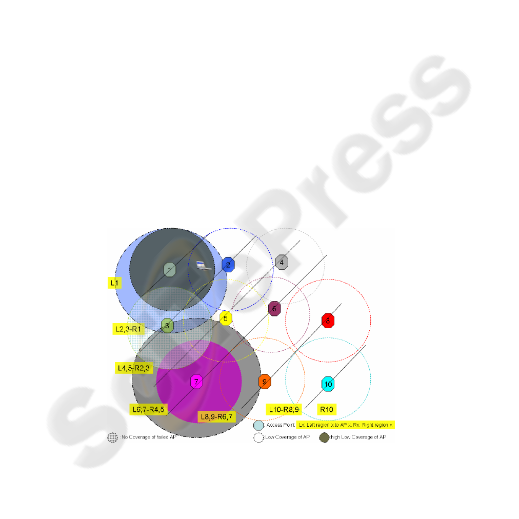
across multiple APs has been suggested in this paper as described in Figure 1. As
shown in Figure 1, the dotted circle indicating the coverage of a particular AP. This
coverage might overlap with adjacent AP, where interference is caused if both APs
are running at the same channel radio frequency. At the same time mobile terminal
falling within the overlapped region would have the choice to have association with
either AP. Each AP has 2 coverage areas; low coverage as shown in the dotted circle
for AP-2, Ap-4, and AP-5, and high coverage as shown in the blue solid circle of AP-
1, and in the grey solid circle of AP-7. The AP-1 and AP-7 have also low coverage
area as shown in the dark grey solid circle, and pink solid circle for AP-1 and AP-7
consecutively. The solid circle for AP-3, with dashed pattern indicates a failed AP,
where its coverage has been substituted by the high coverage area of AP-1 and AP-7.
This architecture improves the WLAN performance by reducing the interference
through assigning different channel radio frequency to adjacent as described in
section 2.1. This architecture also improves the performance in load balancing as
well as reducing the congestion by dividing The coverage region of every AP is
divided in 2 regions, left hemisphere and right hemisphere, where mobile terminal
would choose to associate with one AP according to its location in the left or right
hemisphere of the AP as described in the subsection 2.2. It also improve the WLAN
performance by providing high network availability and fault tolerance through
broadcasting 2 coverage levels by every AP to substitute for the failing AP coverage
area to allow mobile terminal falling within the failed AP to use the WLAN as
described in subsection 2.3.
Fig. 1. Distributed APs Management Techniques with Fault Tolerance.
68

2.1 Distributed Dynamic Channel Assignment
The performance of a network depends, in part, on the assignment of radio channels
to APs. This assignment is often done using a manual process in which the designer
attempts to assign the channels in a way that minimizes co-channel overlap. The
coverage areas, and therefore the channel assignments, are dependent on among other
things such as the radio propagation environment. Since the radio propagation
environment changes, so one cannot be sure that the channel assignments valid at the
time the network was designed will continue to be valid.
However, distributing
channel assignment between APs according to its channel frequency that minimize
the overlap between these frequencies would reduce the interference between these
channels as described in [10] where the assignment of channel frequency to adjacent
APs, are spread from minimum frequency to maximum which cause less interference
between these APs. Example Adjacent APs 1, 2, 3 are assigned channel number 1, 6,
11 consecutively, and APs 4, 5, 6 are assigned channel number 2, 7, 10 consecutively.
Distributed Dynamic Channel Assignment would add extra flexibility to assign a
proper channel number to different AP dynamically according to AP index number.
This dynamic assignment would help in replacing failed AP with another one using
the same index number. Each AP requires having an index number that can be set at
the initialization stage.
2.2 Load Balancing and Terminal Association
Since an AP and its associated clients share a limited bandwidth resource, APs can
become overloaded, leading to congestion and poor network performance. WLAN
equipment with this capability can enhance network performance considerably.
Association between a client and an AP begins with an association request that is
initiated by the client. This association request is normally preceded by the client’s
transmitting one or more probe requests on channels it selects. In each of these probe
requests, the client asks for a response from all APs operating on that channel and
able to receive the client request. This tells the client which APs are within radio
range, and the signal strengths received from the APs give an indication of which
APs will be able to provide higher-quality service. Before sending an association
request, a client should also have previously sent an authentication request that has
been granted.
The method by which a client decides with which AP to request
association is not specified in the IEEE 802.11 standard.
However, the association between mobile terminals in distributed dynamic
management can be controlled not only according to signal strength which cause
network congestion at some AP, but also according to its location in the right or left
hemisphere of the AP [9]. This management technique works according to
distributing the load between adjacent APs where mobile terminal fall within the
overlapped region would be associated only with one AP located to its right
hemisphere. If mobile terminal located within the overlapped region, the signal
strength would not be used to determine to which AP it will associate with. In fact,
the mobile terminal location would be used to distributed load to different AP, where
it will associate with AP that is located at the right hemisphere of itself. As shown in
69

Figure 1, if mobile terminal located anywhere within the region of AP-1 without
overlapping with other AP, it always associate with this AP-1. However, if it locates
within the overlapped region of AP-1, and AP-2, it will associate with AP-2 where
the terminal is located at the left hemisphere of AP-2.
2.3 WLAN with Fault Tolerance
WLAN with multiple AP suffer from network unavailability when one or more AP
failed. This will cause some mobile terminals falling within the area of the failed AP
to lose connection and become unable to use the network. The distributed architecture
suggested previously in section 2 has the advantage of providing fault tolerance. This
is done by increasing the broadcasting power of the adjacent APs of the failed one to
high coverage to cover the area of the failed AP. In order for this architecture to
work, each AP should operate in 2 level of coverage power. Each AP would also
detect the failed neighbor AP through continuous broadcast management signal that
occurs at specific interval of time, where each AP will broadcast its available network
table for all adjacent APs that have sensitive antenna to detect it. The available
network table would be updated by each AP when it receive broadcast from
neighboring APs, where after few broadcast the table would contain a list of all
operating AP that belong to the same network as explained in the following sequence
diagram. Assume in this diagram that AP-1 has joined the WLAN and broadcasted its
own availability network table (that contains list of known AP {1}) to neighboring
APs (AP-2, and AP-3). AP-1 also receives broadcast from AP-2 and AP-3. The
management signal received from AP-2 would contain a list of all APs (2, 4*, and 5*)
that are neighbor to AP-2, where 4* is the list of APs for AP-4 that had been received
previously at AP-2 from AP-4. The list 4* indicating another list of AP-4 that
contains the list of APs that are neighbor of AP-4 which are AP-5 and list of AP-7
(7*). Also list from AP-5 (5*) would contain the list of AP-5 that are neighbor of AP-
5 which are (3, 4, 6, 7, 8). At the same time the list received from AP-7 would contain
the list of APs that are neighbor to AP-7 which are (4, 5, 8, 9). Eventually, the
availability table at AP-1 would contain a list of all APs that are belonging to the
same network. The other APs would also update their availability table which also
would include the list of all APs of the same network. If one of the AP failed
(example Ap-3) as shown in figure 1, all of its neighbor APs (AP-1, and AP-7) would
not receive a regular broadcast from it. If AP-1 and AP-7 didn’t receive broadcast
management signal from its neighbor AP-3, they will assume a failure on AP-3 and
adjust their coverage power to operate at high level. This will allow AP-1, and AP-7
to cover the area of the failed AP-3 as shown in figure 1 (blue solid circle, and grey
solid circle).
70
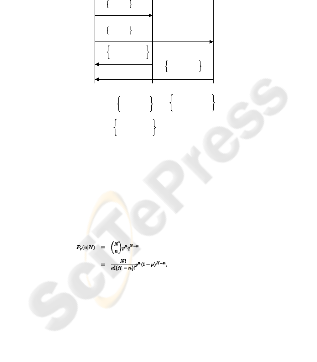
Fig. 2. Sequence of broadcast management at AP.
3 Analysis Results
The binomial distribution gives the discrete probability distribution )/( NnP
p
of
obtaining exactly n successes (terminal falling only within a particular AP range eg.
AP-5) out of N Bernoulli trials or terminals falling within the coverage of a particular
AP and its neighbors APs (where the result of each Bernoulli trial is true with
probability p and false with probability
pq
−
=
1
). The binomial distribution is
therefore given by:
(1)
(2)
where
⎟
⎟
⎠
⎞
⎜
⎜
⎝
⎛
n
N
is a binomial coefficient.
Assume that the desired probability of terminals falling within one Access Point (eg.
AP-5) only is
8.0=p . Therefore the probability of failure is 2.01 =
−
=
pq . The
AP-1
AP-2 AP-3
1
1
2, 4*, 5*
3, 5*, 6
4* =
5, 7*
5*=
3, 4, 6, 7*, 8
7* =
4, 5, 8, 9
71

total number of terminals (trials) is 50
=
N . According to binomial distribution of
formula 2, the probability of at least up to i terminals is falling within only one AP
(eg. AP-5) is:
knk
i
k
pp
kkn
n
ixp
−
=
−
−
=≤
∑
)1(
!)!(
!
)(
0
(3) (3)
The probability that more than i terminals are falling within the same AP is given by:
knk
i
k
pp
kkn
n
ixpixp
−
=
−
−
−=≤−=>
∑
)1(
!)!(
!
1)(1)(
0
(4) (4)
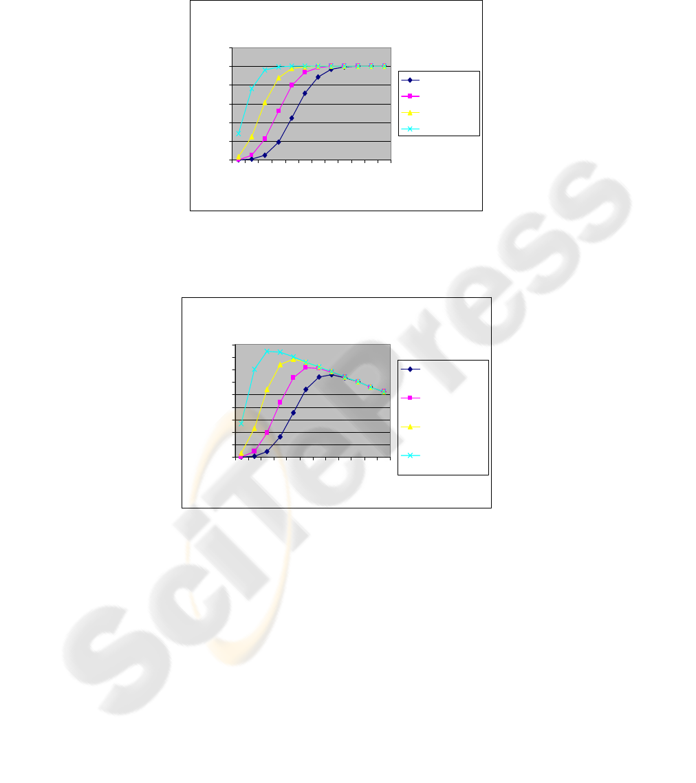
Using formula 4, we can obtain the probability for more than i terminals are falling
within AP-5 according to different value of i {i=20 to 48} as shown in Figure 3. As
shown in this figure, the probability would reach one when desired probability is 0.8
if the number of terminals is 32. The number of terminals would increase to 42 if the
desired probability increases to 0.95.
According to distributed management and using binomial distribution, the total
number of terminals that are only falling within AP-5 can be obtained by the
following formula as shown in figure 4:
)( ixpiT >×=
(5)
Using signal strength terminal management the total number of terminals that are
falling within AP-5 is N. Hence the advantage of using distributed management is
reducing the number of terminals associated with a particular AP (eg. AP-5) by:
(
)
ixpiNTN >×−=−
(6)
If AP failed and its load distributed equally among 3 neighbor APs then extra load
would be added to its neighbor AP in addition to formula 4 as follow:
3)1(
!)!(
!
213)()(
0
⎟
⎟
⎠
⎞
⎜
⎜
⎝
⎛
−
−
−=≤+>
−
=
∑
knk
i
k
pp
kkn
n
ixpixp
(7)
As shown in figure 4, the maximum total number of terminals depends on the desired
probability. When the desired probability is 0.95, the maximum number is 43
terminals. This number drops to 32 when the desired probability is reduced to 0,8.
Using signal strength terminal management the total number of terminals that are
falling within AP-5 is N.
As shown in figure 5, the total number of terminals falling within the same access
points using signal strength is N (50 terminals) independent of the desired
probability. The total number of terminals using distributed management depends on
the desired probability, where the total number would be 32 at desired probability of
0.8, and it increases to 43 when the desired probability increases to 0.95. Hence, the
total number of terminals falling within the same AP using distributed management
drops by 1-32/50 (35%). This would allow terminals to have better bandwidth
allocation using the distributed management scheme.
Using
formula 7, figure 6 shows that at desired probability of 0.8, the probability of
40 terminals joins one AP when there is a failed AP is 0.6 higher than 0.4 when there
is no AP failure. This increases of terminals associating with one AP is caused by the
failure of neighbor AP where its terminals re-associate with other AP that fallen
within its range after increasing its power coverage. Figure 7 shows similar effect of
72
adding extra load to AP caused by terminals were associated with the failure AP and
re-associated with neighbor AP after the failure.
Probability distribution p(x>i)
0
0.2
0.4
0.6
0.8
1
1.2
48 46 44 42 40 38 36 34 32 30 28 26
Number of terminals (i)
probability
desired p=0.8
desired p=0.85
desired p=0.9
desired p=095
Fig. 3. Binomial Probability Distribution.
Total terminals p(x>i)
0
5
10
15
20
25
30
35
40
45
48 46 44 42 40 38 36 34 32 30 28 26
Number of terminals (i)
maximum number of
term inals
Total Terminals,
desired p=0.8
Total Terminals,
desired p=0.85
Total Terminals,
desired p=0.9
Total Terminals,
desired p=0.95
Fig. 4. Total number of terminals.
73


4 Conclusion
The architecture that has been described has the potential to improve performance,
and deployment effectiveness in enterprise and other large-scale wireless LANs, and
at the same time maintain a high network availability and reliability through network
fault tolerance that is based on dynamic power coverage assignment. These
improvements arise from the distributed dynamic resource management deployed in
mobile terminals and APs.
The suggested technique assists the APs to optimize its performance by
dynamically allocating different frequency to adjacent AP in order to reduce the
signal interference. In addition, the association between mobile terminals and AP are
distributed to different APs according to their location in the left or right hemisphere
of the AP. Furthermore, fault tolerance has been provided through the dynamic power
coverage assignment. The effect of fault tolerance improves the network availability,
but it increases loads on APs. This increase of load would be temporarily until the
failed AP has been replaced by working one.
References
1. IEEE 802.11, “Wireless LAN Medium Access Control (MAC) and Physical Layer (PHY)
Specifications,” 1997.
2. Kyriazakos, S. Karestos, G “Practcial Resource Management In Wireless Systems”. Book
Reviews/Edited by Andrzej Jajszczyk IEEE Communications Magazine November 2004.
3. Ush-Shamszaman, Z., Razzaque, A. “A Mobility Management Scheme in All-IP Integrated
Network”, Proceedings of the 23
rd
IASTED International Multi-Conference Parallel and
Distributed Computing And Networks, February 15-17, 2005 Innsbruck, Austria.
4. DaSilva, L., Midkiff, S., Park, J., Hadjichristofi, G, and Davis, N.“Network Mobility and
Protocol Interoperability in Ad Hoc Networks”, IEEE Communications Magazine •
November 2004
5. O’Hara, B., Petrick, A.: The IEEE 802.11 Handbook: A Designer’s Companion, IEEE
Press, 1999.
6. Chhaya, H., Gupta, S. “Performance of Asynchronous Data Transfer Methods of IEEE
802.11 MAC Protocol,” IEEE Pers. Commun., vol. 3, no. 5, Oct. 1996, pp. 8–15.
7. Hills, A. “Large-Scale Wireless LAN Design,” IEEE Commun. Mag., vol. 39, no. 11, Nov.
2001, pp. 98–104.
8. HILLS, A. “Radio Resource Management in Wireless LANs”, IEEE Radio
Communications • December 2004
9. Kbar, G. Mansoor, W. “Mobile Station Location based on Hybrid of Signal Strength and
Time of Arrival”, International Conference on Mobile Business ICMB2205, Sydney,
Australia July 11-13, 2205.
10. Kbar, G. Mansoor, W, “Distributed Resource Management in Wireless LANs”,
International Research Conference on Innovations in Information Technology (IIT2005),
Dubai, UAE, 2005.
11. http://www.stat.sc.edu/~west/applets/binomialdemo.html
12. Gandhi, R. “Tolerance to Access-Point Failures in Dependable Wireless Local-Area
Networks”, Object-Oriented Real-Time Dependable Systems, 2003, Ninth IEEE
International Workshop on Object-Oriented Real-Time Dependable Systems
(WORDS’03F).
75
