
INTERACTIVE 3D PRODUCT ASSEMBLER FOR THE WWW
A Case Study of a 3D Furniture Store
Sophia M K Soo, Stephen C F Chan
Department of Computing, The Hong Kong Polytechnic University, Hong Kong
Ke
ywords: Assembling Mechanism, Parametric Object-Oriented Grouping Method, Assembly ML
Abstract: We describe a system that allows customers to interactively select, assemble, and modify 3D products over
the WWW, enhancing the usage of 3D techniques for e-business. It provides a framework for a web-based
3D assembling system that can significantly simplify the assembling process while retaining enough
flexibility to build an approximate model of real products. The assembled object is captured in a two-level
architecture. Components are first connected using simplified and automatic assembling mechanism; then a
bundle of connected components are grouped together by a parametric object-oriented grouping method.
This grouping method parameterize the components to build a group of descriptive, featured and related
object types - product, part and primitive within the assembling model. The system enhances the flexibility
and efficiency for the assembling process over the WWW. For archival and data transfer, we developed an
assembly-specific data format – Assembly ML. In the prototype implementation of our interactive 3D
assembler (I
3
DA), we integrated an intelligent decision helper to assist casual customers in selecting and
assembling their desired product.
1 INTRODUCTION
Using 3D visualization techniques in the web can
enhance consumer satisfaction through an
experience that comes closer to the “touch and feel”
of the brick-and-mortar environment, giving the
web-customer greater confidence in their purchase
decisions, and eventually help to promote
e-commerce for enterprises. There are many
commercial websites using 3D visualization
techniques to enhance their product presentation.
However, they are mainly limited to viewing the
models at different angles and distances. In this
paper, we describe an interactive 3D assembler
(I
3
DA) that is suitable for the web and e-commerce
websites.
The assembling task is rather complex and
challenging, involving many interactive, connective
and modification tasks. The general problems are:
1. Requirement of highly sophisticated geometric
and spatial skills in a 3D space :
At a first glance, assembling
components may seem to be intuitive and
straight forward, since human beings do that
all the time in real life. In reality, it requires
highly sophisticated skill to perform accurate
translations, rotations and scaling of the
geometries in a 3D space, particularly in the
environment of the common window-
keyboard-mouse computer interface. An
easy-to-use user interface must be developed
so that the assembling process can be
simplified for the average web user.
2. Need for a modifiable assembly structure :
A simple and intuitive way to create a
composite product is to create an assembly as
a bundle by attaching the components one by
one. However, when the assembly is modified
subsequently (e.g. enlarged), the model has to
be modified on a per-component basis -
because the changes required on each
component may be different. For models
which contain large numbers of components, it
can be quite tedious to change components
individually. An intelligent grouping
mechanism is necessary in the assembling
process to allow more efficient modifications.
Grouping is a popular mechanism in
many 3D authoring tools. When the user
changes the properties of the top component in
the group, the changes will be propagated to
all other components in the group. This is
useful, e.g., for the user to move a group of
components by moving the top level object.
However, this traditional grouping function
does not provide sufficient help in the
assembling process.
126
M K Soo S. and C F Chan S. (2004).
INTERACTIVE 3D PRODUCT ASSEMBLER FOR THE WWW - A Case Study of a 3D Furniture Store.
In Proceedings of the Sixth International Conference on Enterprise Information Systems, pages 126-133
DOI: 10.5220/0002616801260133
Copyright
c
SciTePress

The assembling process requires that
when properties of any group component
changes, all other group components will also
be changed relatively but generally differently.
An obvious example is the preservation of
shape, since this kind of adjustment is
frequently required. Using a drawer as an
example: if the user modifies the size of the
drawer’s bottom panel, all other components
need to be changed in size with different
values to preserve the overall shape. These
cannot be easily achieved using traditional
simple grouping methods. The parametric
object-oriented grouping method is designed
to deal with this type of problems. This
grouping method parameterizes all
components to build a more concrete and
representative object in the assembling model.
It makes it more intuitive for the user to
specify the modifications, and generally makes
the assembling process more efficient.
3. Incompatibility to well-established standards :
Some current techniques for Web 3D,
such as VRML (VRML 1997) and X3D (X3D
2003), only record the geometry of the 3D
model, but do not provide support for
assembly information on the model. Hence a
lot of assembling information will be lost
when data is exchanged with other
well-established standards in manufacturing.
In this project, an assembly ML data format is
introduced for the assembly-specific model.
To illustrate the functionalities of an I
3
DA, an
online office furniture store is used as a target
application. The store allows the user to tailor-made
his/her furniture online, and then makes a quotation
or order. It requires a number of functionalities that
can be easily generalized to other applications.
I
3
DA utilizes the Java Applet and Java3D
technologies (Java3D 2004
). This enables our
application to be run on any platform, and to be
embedded in the web page. Figure 1 shows the
architecture of I
3
DA. It demonstrates the overall
design of our assembler.
2 PREVIOUS WORK
Much research have been conducted on the
integration of 3D technology to e-commerce and
manufacturing on the Internet.
Jayaram et al. (1997)
describes a virtual assembly environment for
manufacturing industry. It aims to enhance the
design and production process for the engineer and
designer. The system is not suitable for general web
users. Some researches such as
Varlamis et al. (2000)
and some web sites such as IKEA’s (IKEA 2003)
aim to support to virtual room construction. The
room assembling technique is not suitable for
product assembling as they have different design
processes and constraints. Some researches such as
Lescinsky et al. (2002), Blanchebarbe et al. (2001) aim
to support manipulation of 3D objects in display
scenes, but still fall short of actually changing and
assembling products in a design environment.
Nousch et al. (1999) describes a specialized
web-based program for user to modify the closet
design by direct interaction with the visualized 3D
model. It also provides knowledge-based system to
ensure that the design is obey the relevant design
rules. And finally a shopping list of all needed parts
and customized multimedia assembly manual are
generated for user. Its idea is similar to our approach
that creates a virtual environment for user to design
and modify their 3D products. However,
Nousch et al.
(1999)
discusses only on the special construction of
closet but not general products. It only solves the
assembling problems specific for closet. Also it does
not provide a general 3D assembling system. Our
research provides a framework for a web-based 3D
assembling system that can significantly simplify the
assembling process while retaining enough
flexibility to build an approximate model of real
products for average web users.
3 ASSEMBLING LAYER
3.1 Object Definition
This layer defines the basic operations of the
assembling mechanism, which is to connect the
basic components (smallest pre-defined units), in
order to make up the model.
3.2 Design of the Assembling
Mechanism
The operations (the user interface provided)
supported by our assembling mechanism parallels
the procedures with which human beings assemble
real objects. A processor (of the interface) then
performs automatically most of the complex 3D
assembling operations. This simplifies the usage of
the mechanism, while maintaining the simulation of
reality for the customer. To visualize the operations
of our mechanism, one can imagine the many ways
in which two boxes (Box1 and Box2) can be
attached to each other (see Figure 2). The flow
diagram and description of the assembling process
are shown in Figure 3.
INTERACTIVE 3D PRODUCT ASSEMBLER FOR THE WWW - A CASE STUDY OF A 3D FURNITURE STORE
127
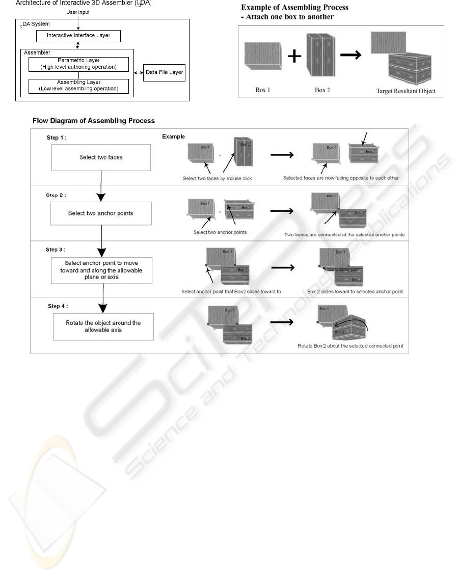
Figure 1
Figure 2
Figure 3
4 PARAMETRIC LAYER
4.1 Object Definition
In the assembling layer, the assembling model is
controlled on a per-component basis. This layer has
no intuitive parameter for the user to control the
model. In the real world, the model is always made
up of some parts, and the parts are made up of
smaller components. In this layer, to simulate the
model in the real world, a new grouping method –
parametric object-oriented grouping method, is
introduced to better control the assembling model.
This grouping method is to parameterize the
connected components to become a group of
descriptive, featured and related objects with type of
product, part and primitive (smallest component).
Parameterized objects have their own properties.
The new grouping method enhances the model
control from per-component basis to per-object basis.
In this grouping method, components or group of
components can be defined as primitive, part or
product. Figure 4 demonstrates the definition and
relationship of the three object types within the
model.
In Figure 4, the part diagram illustrates that
primitives make up the part; the product diagram
shows that parts make up the product; and the
compact version diagram shows the relationships
between the product, parts and primitives. The
properties of primitive, part and product are also
listed in the centre of the figure. To the right of the
figure are examples for each type of diagram. A
drawer unit contains a frame and three drawers; the
drawer unit is a product; frame and drawer are parts;
bottom, top, back, left and right are primitives. In
our model, each component will be a primitive of a
part, a group of components will be a part of a
product.
ICEIS 2004 - HUMAN-COMPUTER INTERACTION
128
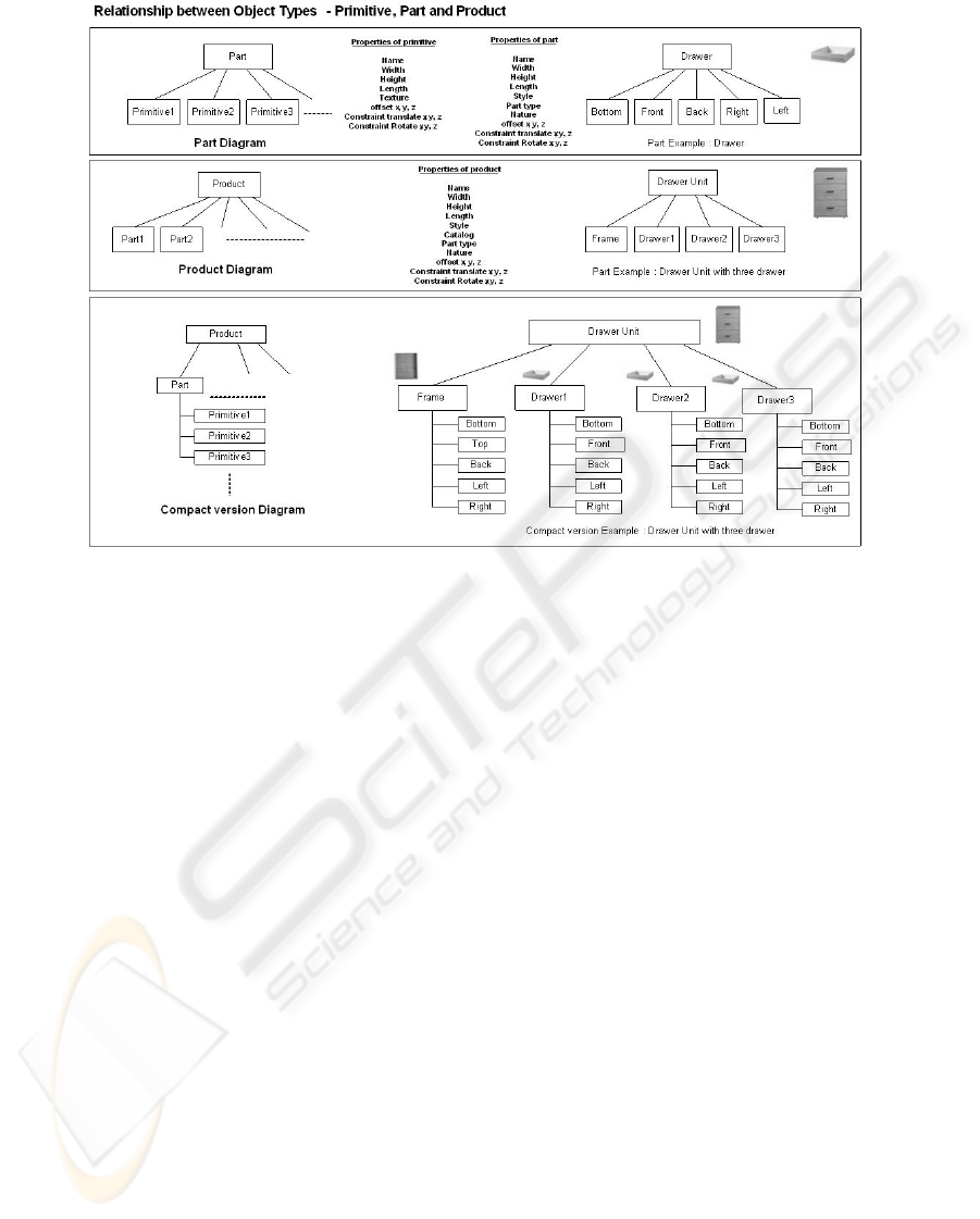
Figure 4
This object definition is more product-oriented,
and more intuitive for the user to specify the design
and modification. For a complex model with
hundreds of components, the user can request a
modification with only a few parameters, letting the
parametric relationships between the product and
parts and primitives to effect the eventual
modifications, instead of specifying hundreds of
component modifications. This layer improves the
flexibility and efficiency of adjustments of the
model with minimal user interaction. This
enhancement is demonstrated in next section 4.2.
4.2 Relationship between Parametric
Layer and Assembling Layer
In the assembling layer, the components are
attached/connected. As Java3D technology is used to
implement our graphical assembler tool, a
hierarchical scene graph concept is used to represent
the spatial hierarchy of the connected components.
In this case, the parametric layer is added upon the
scene graph hierarchy. The relationship between the
parametric layer and the assembling layer is
illustrated in Figure 5. Each component of the model
has a parameterization that defines its object-
belonging relationship with other components within
the model. When the parameterized model is altered,
modifications are propagated to the components
based upon its belonging relationship.
In Figure 5, product 1 has two parts – Part1
and Part2. Part1 is composed of five primitives. The
primitives in the parametric layer are linked to the
correspondent components in the assembling layer.
If one component is selected in the assembling layer,
its primitive, part and product information can be
obtained by link searching from the assembling layer
to the parametric layer. Then, the selection and
modification process can be per-primitive based,
per-part based and per-product based. This approach
makes the model design and modification more
flexible and efficient. With a few objects relative to
the number of individual components, complex
models comprised of hundreds of components can
be designed and modified efficiently, with very little
user-interaction.
5 DATA FILE LAYER
The data format definition of the assembly model
must contain all the properties and relationship of
the objects in the model, allowing the model to be
restored from the encoded string. A data format
based on XML is defined for this purpose. It aims to
provide a general data file format to represent any
type of assembling models. Apart from capturing all
the useful information, reusability and network
loading are also considered in the design of the data
file.
INTERACTIVE 3D PRODUCT ASSEMBLER FOR THE WWW - A CASE STUDY OF A 3D FURNITURE STORE
129
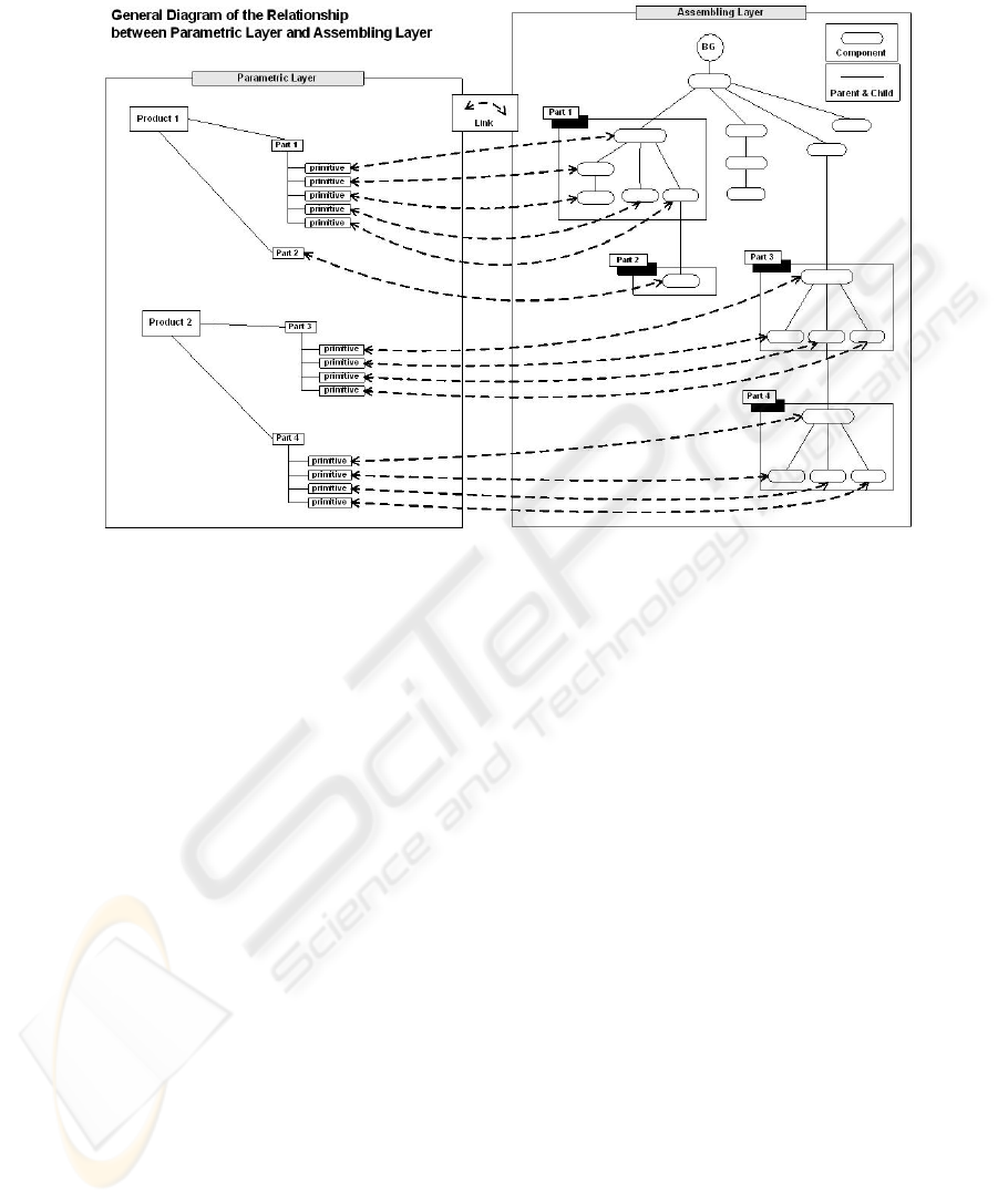
Figure 5
5.1 Assembly ML
The data format – Assembly ML is based on XML. It
is illustrated by an example of a bookcase which has
a child of a drawer unit (see Figure 6). The data file
needs to capture all the parent-child relationships.
Product object “Bookcase” is a “base object”.
It has a “Drawer unit” as its child. Each child will
have connection attributes such as “part attached to”
(part1), “part attached at” (part2), “primitive
attached to” (subPart1), “primitive attached at”
(subPart2), “face to” (face1), “face at” (face2),
“anchor point attached to” (JP1), “anchor point
attached at” (JP2) and offset to represent their
connection. In this example, “Left” of “frame” of
“Bookcase” joins with “Right” of “frame” of
“Drawer unit”.
A child is represented by a URL or filename
that contains the encoded string instead of having a
nested structure in the parent encoded string. This
makes the encoded string of the composite objects
reusable and sharable. Also, when the assembly
model is modified, only those data files containing
modified components need be altered. Therefore, the
number of file transfers and data volumes can be
greatly reduced, helping to reduce the network load
on the Internet.
6 INTERACTIVE INTERFACE
LAYER
The design of our I
3
DA aims to provide high level
methods for building different kinds of product
assemblies. However, there is generally a gap
between the customers’ desires and the capabilities
of the underlying geometric model. Our 3D
assembler layer still requires an intelligent and
user-oriented interface layer on top of it, to allow
casual users to select and assemble products
efficiently.
6.1 User-friendly and easy-to-use
The construction procedure should be clear, intuitive
and “life-like”. Figure 7 demonstrates the user
constructing a custom furniture in four easy and
straightforward steps.
6.2 Fitness Recommendations
Customers do not always know the exact dimensions
of the desired furniture. In such cases,
recommendations can be provided to make his/her
most comfortable, fitting furniture - fitting to the
customer’s size, installed objects, or home space.
ICEIS 2004 - HUMAN-COMPUTER INTERACTION
130
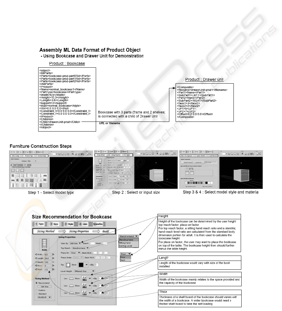
6.2.1 Size Recommendations
The customer may need to fit the furniture to his
space or his height. An intelligent module in the user
interface can calculate the appropriate size of the
furniture based on the following factors: human
body dimensions, objects installed on/into the
furniture, number of users of the furniture, house
dimensions and other furniture dimensions. The
factors considered by the recommendation module
for the bookcase are shown in Figure 8.
6.2.2 Style & Material Recommendations
Some customers may like the design, but
cannot figure out the type of materials. In this case, a
tool can choose appropriate materials which match
the other furniture in the designated room.
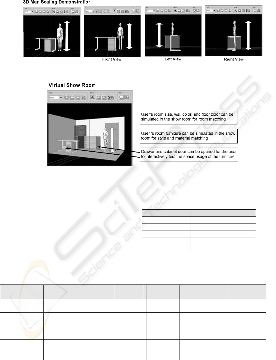
6.3 Fitness Demonstration
The assembler should provide some environments
for the user to validate that the tailor-made model is
fitting in terms of size, style and materials, etc. A 3D
man (Figure 9) in the user’s height and a virtual
show room (Figure 10) are developed to provide a
more realistic environment for examination by the
user.
Figure 6
Figure 7
Figure 8
INTERACTIVE 3D PRODUCT ASSEMBLER FOR THE WWW - A CASE STUDY OF A 3D FURNITURE STORE
131
User Height
User Height
User Height
U
s
e
r
H
e
i
g
h
t
Figure 9
U
s
e
r
H
e
i
g
h
t
Figure 10
7 EVALUATION
The online office furniture store is an example
application to validate the design of our I
3
DA. The
tables (Table1, Table2, Table3) below summarize
our experiences in the development of the
assembler.
Table 1: Type of models that can be built by the 3D
assembler
Type of model Built by Assembler
Table Yes
Bookcase Yes
Cabinet Yes
Drawer Unit Yes
Room Yes
*Yes: model can be built by the assembler
Table 2: Validation of the efficiency of the assembly model by considering the number of user interactions (UIs) required to
change all components in an assembly – No. of UIs required in per-components basis (changing each component
individually) and the no. of UIs required in per-object basis (changing the assembly product model)
Model Action Total
components
Total
Objects
No. of UIs
(Per-Component )
No. of UIs
(Per-Object )
Table with four
legs
Change attributes of table top
and four legs in different values
5 1 x Frame
4 x Legs
5 5
Bookcase with
three shelves
Change attributes of a frame and
three shelves in different values
8 1 x Frame
3 x Shelves
8 4
Drawer Unit with
three drawers
Change attributes of a frame and
three drawers in different values
20 1 x Frame
3 x Drawers
20 4
Cabinet with three
shelves and two
doors
Change attributes of a frame,
three shelves and two doors in
different values
10 1 x Frame
3 x Shelves
2 x Doors
10 6
ICEIS 2004 - HUMAN-COMPUTER INTERACTION
132
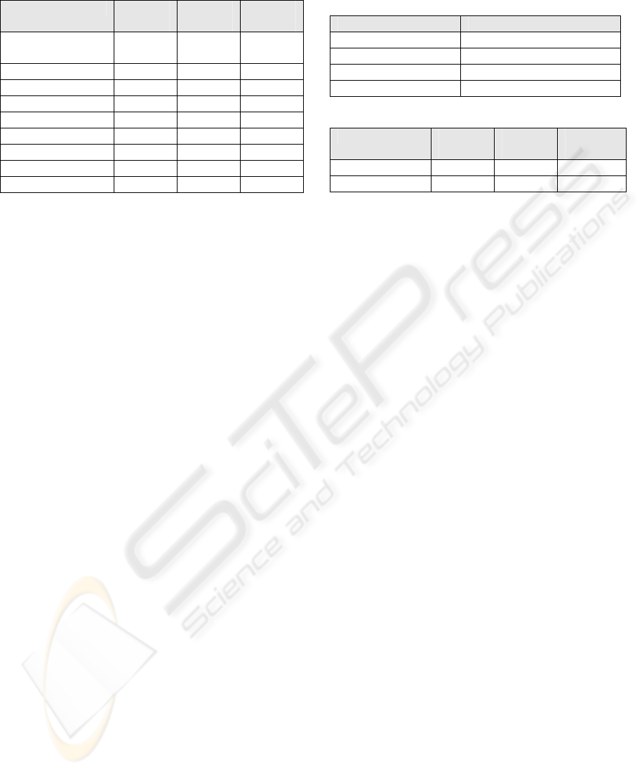
Table 3: Actions on model - Show the flexibility of model assembly
1. Functions on model
Function Apply to
Primitive
Apply to
Part
Apply to
Product
Change position &
rotation
Yes Yes Yes
Change model Style Yes Yes Yes
Change Texture Yes Yes Yes
Change Size Yes Yes Yes
Delete model Yes Yes Yes
Combine models No No Yes
Duplicate model No No Yes
Save model to file No No Yes
Load model from file No No Yes
*Yes: Action can apply to *No : Action cannot apply to
2. Additional functions on specific model
Model Function
Drawer unit Change number of drawers
Bookcase and Cabinet Change number of shelves
Drawer unit Open drawer
Cabinet Open door
3. Constraints on model
Function Apply to
Primitive
Apply to
Part
Apply to
Product
Slide on Surface Yes Yes Yes
Slide on floor No No Yes
*Yes: Action can apply to *No : Action cannot apply to
8 CONCLUSION AND FUTURE
WORK
We described a framework of a web-based
interactive 3D assembler (I
3
DA) system. An initial
prototype of the system, applied to a virtual furniture
store, is implemented. A number of different kinds
of furniture are built, modified and recorded. Based
on the experiences in the experiment, we believe that
the system is general and flexible enough to build
approximate models of real assembling products.
Our experiments show that the number of user
interactions required for design and modification is
greatly reduced, proving that the system can
assemble models in a more intuitive and efficient
way. Further work will be done to extend the
functionality and usability of I
3
DA, and to apply it to
different areas of e-commerce.
ACKNOWLEDGEMENT
This project was partially supported by the Hong
Kong Polytechnic University Research Grand
A.PC54.
REFERENCES
Blanchebarbe, P., Diehl, S., 2001. A Framework for
Component Based Model Acquisition and Presentation
Using Java3D. In Web3D 2001, 6
th
International
Conference on 3D Web Technology, Paderbon,
Germany, ACM 2001. 117-125.
IKEA, 2003. Office IKEA Planning tools.
http://www.ikea.co.uk/ms/en_GB/rooms_ideas/office/
office_planner.html
Java3D, 2004. Sun Microsystems Inc. The Java3D API.
http://java.sun.com/products/java-media/3D/
Jayaram, S., Connacher, H., Lyons, K., 1997. Virtual
Assembly using Virtual Reality Techniques.
Computer-Aided Design. 29(8): 575-584.
Lescinsky, G., Touma, C., Golddin, A., Fudim, M., Cohen,
A., 2002. Interactive Scene Manipulation in The
virtue3D System. In Web3D 2002, 7
th
International
Conference on 3D Web Technology, Arizona, USA,
ACM 2002. 127-135.
Nousch, M., Jung, B., 1999. CAD on the World Wide
Web: Virtual Assembly of Furniture with BEAVER.
In VRML’99, Fourth Symposium on the Virtual Reality
Modeling Language, Paderbon, Germany, ACM 1999.
113-119.
Varlamis, I., Vazirgiannis, M., Lazaridis, I., Papageorgiou,
M., Panayiotopoulos, T., 2000. Distributed Virtual
Reality Authoring Interfaces for the WWW: the
VRSHOP case. In ICME 2000, IEEE International
Conference on Multimedia and Expo (I). 191-194.
VRML, 1997. Web3D Consortium. The Virtual Reality
Modeling Language Specification ISO/IEC
DIS14772-1:1997.
http://www.web3d.org/technicalinfo/specifications/vr
ml97
X3D, 2003. Web3D Consortium. X3D Task Group
Overview. http://www.web3d.org/x3d.html
INTERACTIVE 3D PRODUCT ASSEMBLER FOR THE WWW - A CASE STUDY OF A 3D FURNITURE STORE
133
