
MODEL CHECKING AN OBJECT-ORIENTED DESIGN
Validation Led Development of Software
Simon C Stanton, Vishv Malhotra
School of Computing, Private Box 100, University of Tasmania, Hobart 7001 Australia
Keywords: Finite state process, Object-oriented design, Invariants, Object constraints
Abstract: The object-oriented design methodologies have focused on methods, tools and
representations to build
classes taking advantage of inheritance and encapsulation properties. Modelling of the interaction among
the objects often does not go beyond the method declarations stage until the programming phase. Efforts to
include object constraints in the object-oriented design to embody the behavioural correctness have not
reached the level assertions play in understanding the correctness of the traditional imperative programs.
The paper describes use of a model checker to establish correctness of an object-oriented design.
1 INTRODUCTION
The program execution fundamentals of object-
oriented systems are rooted in the imperative
programming paradigm. The need for invariants and
execution stages (Warmer, 1999; Dijkstra, 1976)
remains important in establishing the correctness
and other properties of the object-oriented programs
and systems. The dominant developments in the
object-oriented domain have focused on class
construction; however, a design is not ready just
because each class has been designed inheriting
behaviour and code from appropriate super-classes.
We need to also be sure that the class objects will
interact with each other correctly.
A methodology exclusively focused on the object
and class inte
rfaces does not address some basic but
important design needs: How do we know that all
object classes have been defined? How do we know
that all methods of interest have been found? How
do we know that all behavioural details of interest
have been captured in the specifications?
Inconsistency in the specifications is another global
property that escapes the confines of a single class
interface. We need a methodology that can consider
properties of individual classes as well as the
properties of a group of classes and their objects.
Imperative languages use procedural abstraction
as t
he central design methodology for understanding
and comprehending software and development
processes. Invariants and predicates (Dijkstra, 1976)
are used to relate the points in the static text of a
program with the (expected) state that would exist
when the correct program reaches those points
during the execution.
More recently, Java – Java 1.4 onwards – has
i
ncorporated the traditional imperative language
style assertions. Thus, through post-conditions
programmers are able to express some, but not all,
aspects of the contracts that object methods have to
the objects invoking the methods. However,
emphasis away from the functional and procedural
paradigms makes it difficult to associate locations in
the static text of an object-oriented program with the
execution stages. It is not convenient to write
assertions defining the system states at various
points during the program execution. The Object
Constraint Language, OCL (Warmer, 1999), has
somewhat limited success in expressing constraints
on the values (states) in programs.
In this paper, we suggest the use of model
checki
ng tools as a way to express and verify
properties that encompass multiple objects and their
classes. Specifically, we use Labelled Transition
System (LTS) by Magee and Kramer (Magee, 1999)
as the verification tool. The tool models a concurrent
system of objects as a composition of Finite State
Process (FSP).
A model is an abstract specification of the
syste
m. Each object is represented as a concurrent
component. The invariant properties of the object-
oriented model can be expressed as the safety
properties over the LTS description. A deadlock or a
liveness concern in the LTS model has interpretation
in the object-oriented domain as underscoring an
issue that has remained unaddressed.
605
C Stanton S. and Malhotra V. (2004).
MODEL CHECKING AN OBJECT-ORIENTED DESIGN - Validation Led Development of Software.
In Proceedings of the Sixth International Conference on Enterprise Information Systems, pages 605-608
DOI: 10.5220/0002600706050608
Copyright
c
SciTePress
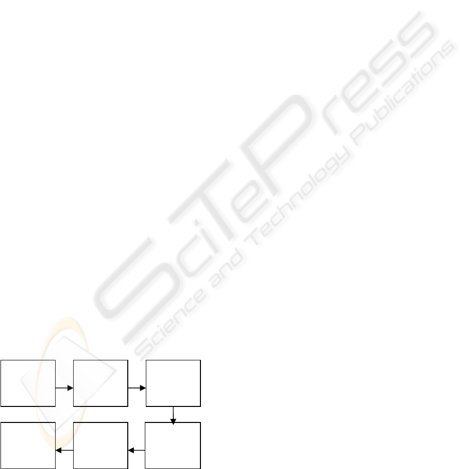
Passenger
awaits
destination
Passenger
leaves the
lift
Passenger
leaves the
system
Passenger
calls a lift
at a floor
Passenger
waits for a
lift
Passenger
enters the
lift
Figure 1: Initial finite state process for a lift
passenger from a text description.
Section 2 describes a software development
process, the LTS specification language and its
processing. In section 3, we give flavour of the kinds
of outputs one receives from the LTS analyser.
Section 4 presents some concluding remarks.
2 SOFTWARE DEVELOPMENT
We follow validation led software development
process (Lakos, 2002). In brief, the object-oriented
software development begins with a text description
of the system. The objects and object classes are
discerned from the text. For each class, some data
members may become obvious at this point. Class
hierarchies and other inter-class relationships are
also represented explicitly to take advantage of the
standard object-oriented modelling methodologies.
To extract consistent and complete specifications,
the methodology advocates the use of object
lifecycle models.
For each significant object class, the text
description provides an initial description of the
object’s lifecycle. For example, verbs provide clues
to the existence of various states. The nature of these
verbs may suggest various forms of transitions
between the states of the system.
Text descriptions are notorious for their
ambiguity and inconsistency. At the same time,
much of the description is generally left
unexpressed. One does not expect the initial
lifecycle models of the object classes drawn from
the text to be perfect models. A validation led
process can be used to iteratively develop the
lifecycles to their final refined levels.
In each iterative cycle of the validation led
development, the lifecycles are matched against each
other to identify inconsistencies and incompleteness.
Each identified lacuna requires the lifecycles to be
revised to correct the concern. The reported
methodology, however, relied on a manual analysis
of the lifecycles to identify the lacunae. A tool to
perform this analysis is a necessary step to improve
the reliability and effectiveness of the methodology.
We address this need by using a model checker
to identify the mismatches in the object lifecycle
specifications. The emerging specification being
formal delivers another potential benefit in the form
of automating the task of program generation. This
paper, however, does not pursue this avenue.
The examples used in this paper are based on the
lift system as described in (Lakos, 2002). Figure 1
shows the lifecycle of a lift passenger as it becomes
evident from the text description of the lift system.
As the validation led process progresses, the
specification gets developed. For example, a
passenger arriving at the ground floor or the top
floor of the building will have a lifecycle somewhat
different from the lifecycles of those arriving at the
other floors.
2.1 Labelled Transition System
Using Labelled Transition System (LTS) (Magee,
1999) we can model the lifecycles of the entities as
Finite State Processes (FSP). The associated system
analyser (LTSA) can analyse the processes for
progress and safety violations. In this section, we
give a brief flavour of FSP descriptions.
A Finite State Process consists of a sequence of
actions. As an action occurs the system changes its
state over a finite set. It is often helpful to define a
finite process in terms of other finite processes. For
example, process PASSENGER below models a lift
passenger (see Stanton 2002 for further details)
const UP = 0
const DOWN = 1
set DIR = UP..DOWN
PASSENGER = {
call_at_ground_level ->
WAITING_FOR_LIFT[1] |
call_at_top_floor ->
WAITING_FOR_LIFT[MAX_FLR] |
call_at_floor[f:2..MAX_FLR-1][d:DIR]
-> WAITING_FOR_LIFT[f]
}
In this model, a passenger can follow one of
three alternative sequences of actions based on the
floor from which he calls the lift. In each alternative,
an action of calling the lift is followed by a wait
(process) for the lift. The passenger waits on the
floor from which he called the lift.
ICEIS 2004 - INFORMATION SYSTEMS ANALYSIS AND SPECIFICATION
606

2.2 LTS Analyser
The LTS analyser (LTSA) can verify a given model
for two kinds of errors. A progress violation occurs
when the system reaches a state from which it can
not guarantee a future occurrence of any action from
a set of actions. For example, a progress violation
would have occurred if we can not assert, at all
instances, that the lift will visit the ground floor
again at some time in the future.
A safety property is a sequence of, not
necessarily consecutive, actions that represent an
acceptable behaviour. Any violation denotes an
error. For example, a safety requirement may insist
that each
door open action is followed by a door
close
action before the lift moves.
Indeed, there is some leeway in modelling
certain conditions: a safety requirement can be
specified as a guard and therefore manifests as a
progress violation rather than as a safety violation.
Composition:
LP = p.1:PASSENGER || LIFT(btnUp,btnDown,dptCount) ||btnUp.1:BUTTON ||
btnUp.2:BUTTON || btnDown.2:BUTTON || btnDown.3:BUTTON || dptCount.1:BUTTON ||
dptCount.2:BUTTON || dptCount.3:BUTTON
State Space:
22 * 882 * 3 * 3 * 3 * 3 * 3 * 3 * 3 = 2 ** 29
Analysing...
Depth 25 -- States: 217 Transitions: 445 Memory used: 4482K
Trace to DEADLOCK:
p.1.arrival.1 // p.1 arrives a at level 1 of the building
p.1.passenger.1 // wants to ride the lift from level 1
p.1.call.1.1 // calls the lift
delay.1 // waits – this lift is right there!
door_is_open_i.1.1 // Lift door opens
dptCount.1.seek_button.0 // Lift checks: the departure count at floor 1 is 0
btnUp.1.seek_button.1 // Lift checks: the up button at floor 1 shows 1 person is waiting
btnUp.1.off // Lift turns the first floor up button off
p.1.enter_lift // Passenger p.1 may board the lift
p.1.entered_lift.1 // p.1 enters lift
p.1.press_dest.1 // p.1 wants to go to floor 1 – same floor
pause
door_is_closed.1.1 // Lift door closes p.1 is inside
dptCount.1.seek_button.1 // Lift determines that it needs to go to floor 1
door_is_open_i.1.1 // Lift opens the door
dptCount.1.seek_button.1 // Anyone getting down here?
p.1.destination_reached.1 // p.1 is to be let off here
p.1.left_lift.1 // p.1 leaves
p.1.arrival.1 // p.1 is back on the level 1
p.1.passenger.1 // wants to ride the lift from level 1. Again!
dptCount.1.seek_button.0 // Lift checks: the departure count at floor 1 is 0
btnUp.1.seek_button.0 // Lift checks: the up button at floor 1 shows 0 persons waiting
btnDown.1.seek_button.1 // Lift checks: the down button at floor 1 shows 1 person is waiting
// btnDown.1 is defined by LIFT(btnUp,btnDown,dptCount)
btnDown.1.off // Lift turns the first floor down button off
Analysed in: 180ms
Figure 2: LTSA analysis report indicating a sequence of actions leading to a deadlock in a FSP model for a lift
system. The comments have been added to provide interpretation for the readers of this paper.
A safety check involves exercising all possible
sequences of the actions to ensure that no safety
violation occurs. Similarly to ensure the absence of
progress violation, the analyser checks all possible
sequences of actions to find a sequence that does not
guarantee a future occurrence of a desired action.
Each safety or progress violation detected by the
tool is reported by LTSA as an action sequence
leading to the error state.
3 EXPERIENCES
This section reports our experiences in the use of the
model checker for validation led development
specifications of the lift problem. Our study
(Stanton, 2002) was focused on the issues related to
the movements of a lift in a multi-floor building. At
MODEL CHECKING AN OBJECT-ORIENTED DESIGN
607
various points in its lifecycle, the lift model invokes
algorithm
WALK to determine its next action. Some
points on the lift lifecycle at which the algorithm is
invoked are: (1) when the lift door closes; (2) when
the lift approaches the next floor level; and (3) by an
idle lift when an on-floor button is pressed to call the
lift.
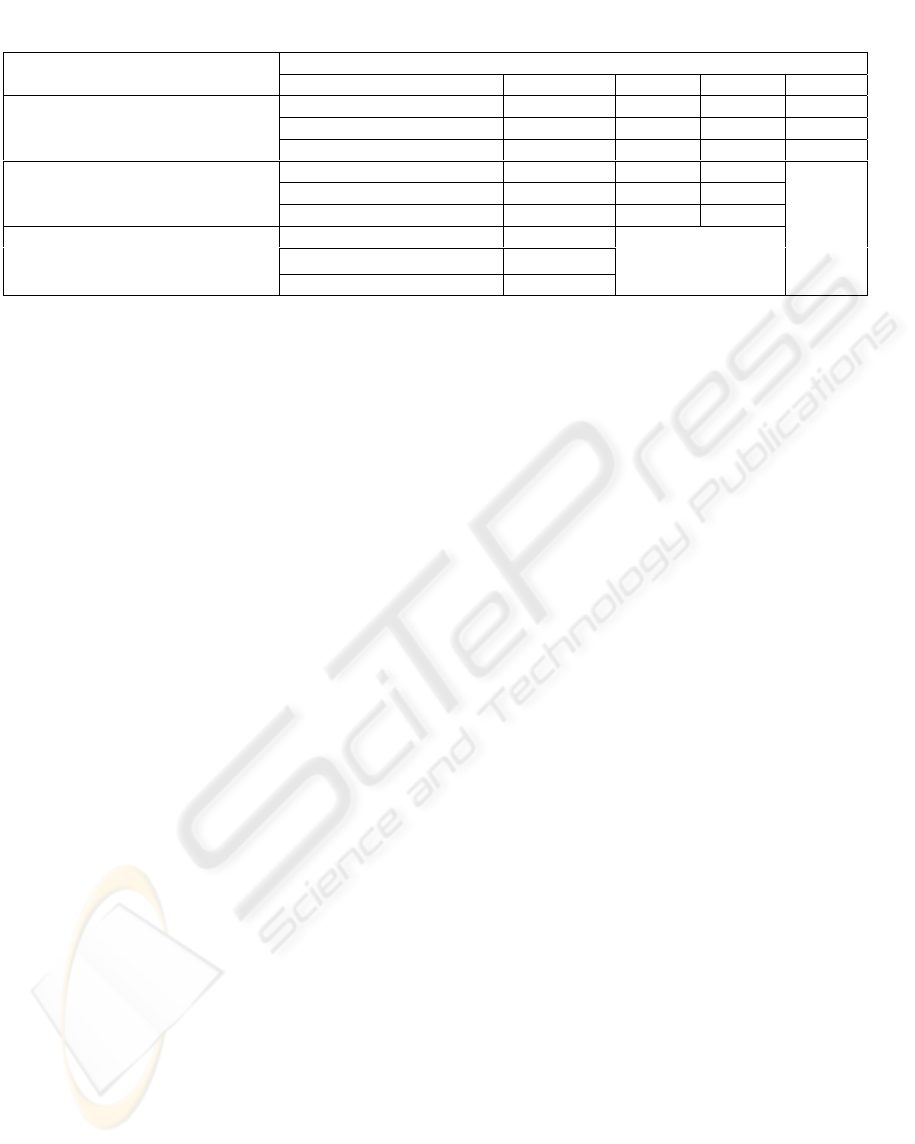
Table 1: State space volume for the modelled lift system and its growth with the floors and simultaneous users.
Number of floors in the modelled building
Number of simultaneous
passengers in the model
3 5 7 10
Reachable states 1267 5067 12987 35952
Potential state space 10
24
~10
33
~10
40
~10
50
1
Number of transitions 1327 5267 13407 36852
Reachable states 56664 697580 3580800
Potential state space
~10
41
~10
58
~10
73
3
Number of transitions 68388 812408 4060332
Reachable states 2966788
Potential state space
~10
57
5
Number of transitions 4337180
Initially a rather rudimentary
WALK algorithm
was derived from the text and coded in the FSP
model. The LTS analyser was then repeatedly used
to report incompleteness and inconsistency errors in
the model. As the errors were reported the WALK
specifications were corrected. Figure 2 depicts an
annotated LTSA report – we have added annotations
to help the reader understand it.
The reader would notice that the description does
not fit with the typical configuration of a real lift
system. For example, there are buttons on the
ground floor to call the lift to go up as well as to go
down. Likewise, a passenger wishing to travel to the
same floor may call the lift for either direction. Their
presence is simply an indication of the still evolving
state of the FSP model used in the figure. The
example model is not the final model.
Table 1 provides an indication of the effort
required to model-check the finite state process
(FSP) model of the lift. These provide some
interesting insights into the traditional testing-based
software design and development methodologies.
A naïve black-box testing (Perry, 1995) would
tend to show growth in the required number of test
cases in proportion to the potential state-space size.
The white-box testing (Perry, 1995) takes advantage
of the implementation and design information. Thus,
it will follow the growth trend shown as reachable
state space and/or as the number of transitions. In
both cases, it is clear that a pragmatic testing effort
can cover only a small fraction of the test cases
needed for a complete check. Besides being more
comprehensive a model-checker catches the errors in
an earlier phase than the testing – a cherished goal of
every software engineer.
4 CONCLUSION
The model checking, notwithstanding its tedium, is a
useful and effective tool in developing high-quality
error-free software. Model checkers, such as LTSA,
contribute to this process in many ways:
• The formal FSP descriptions that a model
checker requires is directly associated with the
objects in the system specifications.
• The FSP description of the objects is formal and
is capable of interpretative execution.
• The verification process employed by a model
checker is like a simultaneous execution of all
animations – analysis provides an effective and
efficient mean for identifying potential errors.
• The formal specifications can be automatically
transformed into programs.
REFERENCES
Dijkstra, E.W., 1976. A Discipline of Programming,
Prentice-Hall. Englewood Cliffs, NJ.
Lakos, C.A. & V.M. Malhotra, 2002. Validation Led
Development of Software Specifications, International
Journal of Modelling and Simulation, 22(1), 57-74.
Magee, J. & J. Kramer, 1999. Concurrency: State Models
& Java Programs, John Wiley & Sons, Chichester.
England.
Perry, W., 1995. Effective Methods for Software Testing,
John Wiley & Sons, NY.
Stanton, S.C., 2002. Validation and Verification of
Software Design using Finite State Process (Honours
thesis), School of Computing, University of Tasmania,
Hobart, Australia.
Warmer J. & A. Kleppe, 1999. The Object Constraint
Language – Precise Modeling with UML, Addison
Wesley Longman Inc., Reading,, Ma.
ICEIS 2004 - INFORMATION SYSTEMS ANALYSIS AND SPECIFICATION
608
