
Analog Electronics Basic Simulator
and Virtual Laboratory
Ángel Salaverría
1,4
, Jacinto G. Dacosta
2,4
, Luis F. Ferreira
4
and Enrique Mandado
3,4
1
University of Pais Vasco UPV/EHU. Dpt. of Electronic and Telecommunication. Spain
2
University of Vigo. Dpt. of Informatics. Spain
3
University of Vigo. Dpt. of Electronic Technology. Spain
4
University of Vigo. Institute for Applied Electronics. Spain
Abstract. This paper describes a basic electronics learning system combining a
hypermedia system explaining theoretical concepts with a basic simulator and a
virtual laboratory to improve the engineering education process on electronics
and the students skills before going to the actual laboratory. To accomplish this
objective the system also provides a set of complementary resources, constitut-
ing a bridge between theory and practice. This new kind of hypermedia tools
takes advantage of the information technologies (multimedia, simulation, etc.)
and also facilitates the self assessment of the students knowledge.
1 Introduction
At present, electronics learning follows the process shown in Fig. 1. First, the stu-
dents learn theoretical concepts by attending lectures and studying bibliography and
finally they perform a set of laboratory works.
Lessons
and/or
books
Laboratory
Lessons
and/or
books
Laboratory
Fig. 1. Electronic learning process
However, this process has several drawbacks because:
• The tutorial included in a book does not give enough information about de
dynamic behaviour of electronic circuits [1] [2] [3].
• The students have an insufficient knowledge about commercial electronics
devices, assembly techniques, and measurement instruments. Design errors
and components damages are common during laboratory classes.
Salaverría Á., G. Dacosta J., F. Ferreira L. and Mado E. (2004).
Analog Electronics Basic Simulator and Virtual Laboratory.
In Proceedings of the First International Workshop on e-Learning and Virtual and Remote Laboratories, pages 20-27
DOI: 10.5220/0001150300200027
Copyright
c
SciTePress

• The students don’t know if their knowledge on theoretical concepts is good
enough.
• The students have no experience on testing electronic circuit behaviour.
Specially they do not have a good grasp of measurement instrument opera-
tion.
By these reasons, we developed a basic simulator and a virtual laboratory to im-
prove the previously described learning process.
2 General Description
Fig. 2 shows the proposed learning process. The tutorial is a hypermedia system ex-
plaining theoretical concepts [4] [5]. When explaining the concepts the students use
the basic simulator to consolidate his knowledge.
Before going to the actual laboratory, they use the virtual lab including a work-
bench area with a power supply, an oscilloscope, a function generator and a proto-
board. Using the interface the student can select the points whose waveforms are
shown on the scope. The virtual lab also includes an area where questions about the
possible circuit fails are indicated.
TUTORIAL
BASIC
SIMULATOR
VIRTUAL
LABORATORY
ACTUAL
LABORATORY
Fig. 2. Block diagram of the proposed learning process
3 Basic Simulator
Available simulators are mainly oriented to circuit design instead of to circuit analy-
sis. Due to that they are not useful for the first stages of the learning process by the
following reasons:
• They use actual models of the components, when just a simplified model is
needed.
• They do not relate theory and simulation.
• They do not have hypermedia capacity nevertheless they need many hard
disk resources.
19

A basic simulator of analog electronics is just developed achieving the following
characteristics:
• It has a graphic user interface including a power supply, two independent
function generators and a three channels oscilloscope.
• It shows the circuit scheme with the function generators connected to the
inputs and the scope channels connected to the adequate circuit points.
• It has links to manufacturer data sheets.
Fig. 3 shows the graphic user interface of the basic simulator.
Fig. 3. Graphic user interface of the basic simulator
The students can change the resistors values clicking with the mouse just over the
component (Fig. 4).
The basic simulations are linked to audio theoretical explanations (Fig. 5).
20

Fig. 4. Using the mouse to change the resistor values
If due to the change of the component values or the amplitude of the input signals
the circuit fails, the interface give an easy identifying signal (Fig. 6).
4 Virtual Laboratory
The basic simulator is a good tool for theoretical concepts learning but it does not
relates theory and practical activities. That is why we also developed a virtual labora-
tory. This computer tool constitutes a bridge to the real laboratory because:
• Teaches the students electronic devices mounting using protoboards (a
widely used system) before they assemble electronic circuits in the labora-
tory.
Fig. 5. Audio theoretical explanation
21

• Teaches the students how to find the most common electronic circuits fails
such as:
- Protoboards with failed contacts.
- Short-circuited or open circuit passive devices.
- Out of order solid-state devices.
- Non-correct values of resistors and/or capacitors.
• Allows students come back to theoretical lessons using hypermedia links.
• Allows students to consult manufacturers’ data sheets.
Fig. 6. Identification of a failing circuit
The system must be used between the theoretical studies and the practical work in
the laboratory. Fig. 7 shows the block diagram of the developed system composed by
three main blocks:
• Workbench area
• Complementary resources
• Data module
22
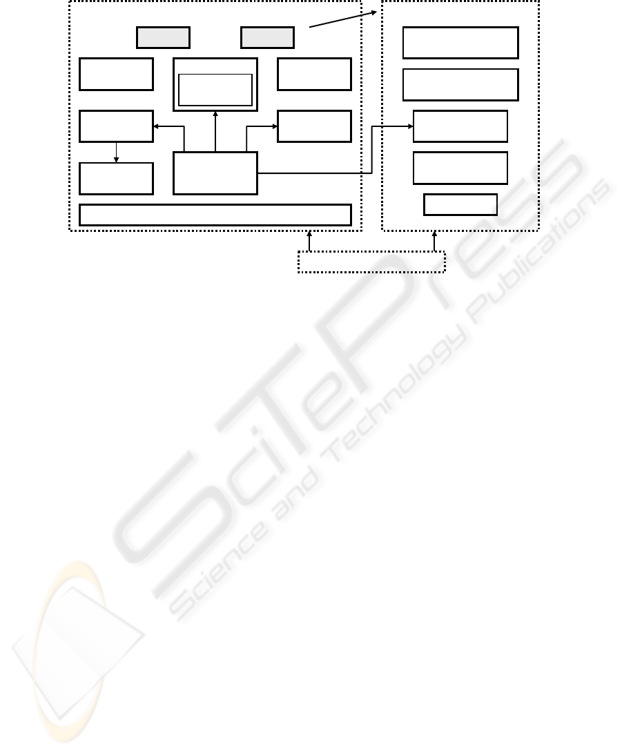
WORKBENCH AREA
Clock Menu
Power
supply
Resistors
colours
Colours
code
Possible answers
Oscilloscope
Functions
generator
Waveforms on
Measure points
Circuit under
test and measure
points
Ohmmeter
DATA MODULE
COMPLEMENTARY RESOURCES
Graphics for protoboard
explanations
HTML files with
theoretical explanations
Manufacturer
documents
Schematic diagram
Under test
Help
Fig. 7. Block diagram of the virtual laboratory
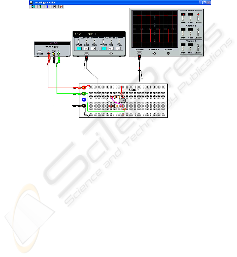
4.1 Workbench Area
Workbench area (Fig. 8) contains:
- A power supply.
- An oscilloscope, where the waveforms may be shown.
- A function generator.
- A protoboard where the circuits are mounted showing the way to opti-
mize the devices placement and interconnections.
- Red circles signaling test points. Clicking on them the oscilloscope shows
the waveform at the selected point.
- The resistor color code, and an ohmmeter.
- An area where possible circuit failures are indicated.
5 Assessment of the System
The system has been tested with 12 students with basic knowledge of circuits theory
and electronic devices fundamentals. . The test has been done as follows: two groups
were done, group A and group B, each one with six students.
Each group was divided in 3 subgroups of two students. While the students of
group A went to the laboratory using only the practice manual being used during
several years, those of group B used the basic simulator and the virtual laboratory
previously. All of them mounted the same circuit with a device (a resistor) out of
order. The three subgroups constituting group A mounted the practical circuit in a
23
different way each one while the three subgroups constituting group B did it almost
equal. Students of Group A spent 4.10, 5.30 and 6.35 minutes to find the fail (mean
time: 5´25”). By the contrary group B students only spent 1.15, 1.46 and 2.03 minutes
to find the fail (mean time: 1´55”, 65% less than A group).
Fig. 8. Workbench area of the virtual laboratory
6 Conclusions
This article describes an analog electronics basic simulator and a virtual laboratory
based on hypermedia resources. Using this system as a bridge between theoretical
lessons and laboratory classes, students improve their performance and increase their
efficiency in the laboratory. The system is modular supporting the addition of new
exercises.
The combination of the basic simulator and the virtual laboratory constitutes a
self-checking system providing students with a tool for testing their level of knowl-
edge.
24

References
1. Cox, James. “Fundamentals of Linear Electronics Integrated and Discrete”. Thomson Learn-
ing (2002)
2. Floyd, Thomas L. “Electronic Fundamentals (4th Edition)”. Prentice Hall (2001)
3. Sedra, Adel S. & Smith, Kenneth. “Microelectronic Circuits (4th Edition)”. Oxford Univer-
sity Press (1998)
4. Terry J., “The ‘M-Word’: Multimedia interfaces and their role in interactive learning sys-
tems”, D.N. Edwards and S. Holland (eds), Multimedia Interface Design in Education, Ber-
lin, Springer-Verlag (1994)
5. Valdés M.D., Moure M.J., Mandado E.: Hypermedia: a tool for teaching Complex Tech-
nologies. IEEE Transactions on Education. No 4. (1999)
25
