
FORCE RIPPLE COMPENSATOR FOR A VECTOR
CONTROLLED PM LINEAR SYNCHRONOUS MOTOR
Markus Hirvonen and Heikki Handroos
Institute of Mechatronics and Virtual Engineering, Lappeenranta University of Technology, Lappeenranta, Finland
Olli Pyrhönen
Department of Electrical Engineering, Lappeenranta University of Technology, Lappeenranta, Finland
Keywords: Cogging, Disturbance Observation, Linear Motor, Velocity Control, Vibration Suppression.
Abstract: A dynamic model including non-idealities for a permanent magnet linear synchronous motor (PMLSM) is
postulated and verified. The non-idealities acting on the physical linear motor are measured and analyzed.
These experimental results are utilized in the model. The verified simulation model is used in developing a
force disturbance compensator for the velocity controller of the motor. The force non-idealities, such as the
cogging force, friction and load force variation, are estimated using a disturbance observer. The acceleration
signal in the observer is derived through the use of a low-acceleration estimator. The significant effects of
the disturbance compensator on the simulated and measured dynamics of the motor are shown.
1 INTRODUCTION
The linear motor is an old invention but it is only
recently that, as a result of the development of
permanent magnets and their decreased costs,
permanent magnet linear motors have become a
viable alternative to rotating motors fitted with linear
transmissions. In machine automation, linear
movement has traditionally been transmitted from a
rotary actuator by means of a ball screw, rack and
pinion or belt. The linear motor simplifies the
mechanical structure, eliminating the contact-type
nonlinearities caused by backlash, friction, and
compliance. In addition, the main benefits of a linear
motor include its high-power density, reliability and
efficiency.
Nowadays, the controllers commercially
available, mainly PID algorithms with fixed gains,
are unable to compensate for the undesirable
phenomena that reduce the precision of motion such
as backlash, static friction, load variations etc. Large
controller gains are needed in order to maintain the
stiff control required when suppressing load
disturbances that tend to reduce the stability of a
system. Therefore, extended methods for the
compensation of disturbance have become an
important topic of research. By compensating for an
unknown time-varying force based on the estimation
of such a force, faster speed responses and smaller
speed ripples can be achieved.
In disturbance compensation, the compensation
technique itself is a very simple feed-forward
control, but the difference arises from the different
disturbance estimation algorithms. In (Castillo-
Castaneda et al., 2001), the friction compensation
has been studied using model-based estimation. One
disadvantage of this technique is that it is suitable
for tracking only, since the desired velocity must be
known in advance. Kim et al. (2002) and Tan et al.
(2002) have studied sliding mode estimators in
compensation feedback, while Godler et al. (1999),
Deur et al. (2000), Bassi et al. (1999) and Hong et
al. (1998) have studied the disturbance observer of a
more general algorithm. Godler et al. (1999)
compared load disturbance compensation with an
acceleration control loop inside a speed loop. They
have found that control implemented using an
acceleration control loop can better tolerate
parameter variation as well as disturbance in
comparison to robust control with a disturbance
observer. On the other hand, Deur et al. (2000)
suggested the use of a disturbance observer in
industrial applications due to its simple
177
Hirvonen M., Handroos H. and Pyrhönen O. (2004).
FORCE RIPPLE COMPENSATOR FOR A VECTOR CONTROLLED PM LINEAR SYNCHRONOUS MOTOR.
In Proceedings of the First International Conference on Informatics in Control, Automation and Robotics, pages 177-184
DOI: 10.5220/0001128001770184
Copyright
c
SciTePress
implementation as well as simple design which has
no robustness constraints.
The motor model discussed in the above-
mentioned papers is a simplified model. The
development of computers and software has made it
feasible to simulate the more detailed dynamical
behavior of machine systems. This paper discusses
the use of a more detailed non-linear dynamic model
for the analysis of a linear transmission system. The
motor studied in this paper is a commercial three-
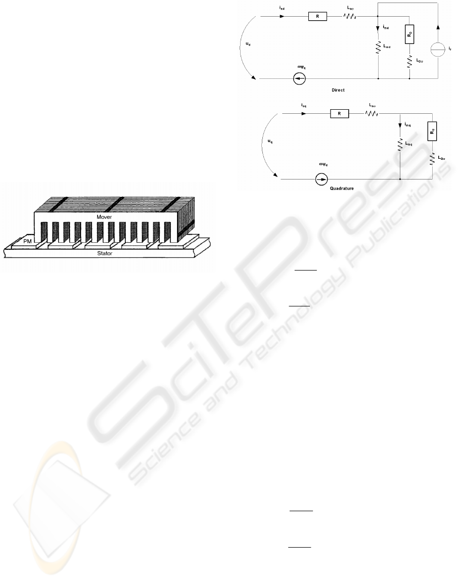
phase linear synchronous motor application. The
moving part (the mover) consists of a slotted
armature and a three phase windings, while the
surface permanent magnets (the SPMs) are mounted
along the whole length of the path (the stator).
Figure 1: The structure of the studied linear motor.
First of all, the equations for modelling the
vector-controlled motor drive and non-idealities are
derived. Then, the simulation model is verified with
the measurements from physical linear motor
applications, and the comparison of the responses is
shown in the study. Finally, a disturbance observer
based on (Hong et al., 1998), (Godler et al., 1999),
(Deur et al., 2000), and (Bassi et al., 1999) is
implemented in the physical motor system after
being tested in the simulation model, and the results
and conclusions are presented.
2 SIMULATION MODEL
2.1 Model of LSM
The modeling of the dynamics of the linear
synchronous motor examined in this paper is based
on the space-vector theory. The time-varying
parameters are eliminated and all the variables
expressed on orthogonal or mutually decoupled
direct and quadrature axes, which move at a
synchronous speed of
ω
s
. The d- and q-axes
equivalent to the circuit of the PMLSM are shown in
figure 2, and the corresponding equations are (1) and
(2), respectively.
The voltage equations for the synchronous
machines are
d
d
uRi
s
dad q
dt
ψ
ω
ψ
=+−, (1)
d
q
uRi
qaq sd
dt
ψ
ω
ψ
=++ , (2)
where u
d
and u
q
are the d- and q-axis components of
the terminal voltage, i
ad
and i
aq
the d- and q-axis
components of the armature current, R is the
armature winding resistance and
ψ
d
,
ψ
q
are the d-
and q-axis flux linkage components of the armature
windings. The synchronous speed can be expressed
as
ω
s
=πv
s
/
τ
, where v
s
is the linear synchronous
velocity and
τ
the pole pitch. Although the physical
system does not contain a damper, which in PMLSM
usually takes the form of an aluminum cover on the
PMs, virtual damping must be included in the
model, due to eddy currents. The voltage equations
of the short-circuited damper winding are
0
d
D
Ri
DD
dt
ψ
=+, (3)
0
d
Q
Ri
QQ
dt
ψ
=+, (4)
where R
D
and R
Q
are the d- and q-axis components
of the damper winding resistance and i
D
and i
Q
the d-
and q-axis components of the damper winding
current. The armature and damper winding flux
linkages in the above equations are
Figure 2: Two axial models of the linear
s
y
nchronous motor.
ICINCO 2004 - ROBOTICS AND AUTOMATION
178
Li L i
dadadmdDpm
ψψ
=++, (5)
Li L i
qaqaqmqQ
ψ
=+, (6)
Li Li
DmdadDDpm
ψψ
=++, (7)
Li Li
QmqaqQQ
ψ
=+, (8)
where
L
ad
and L
aq
are the d- and q-axis components
of the armature self-inductance,
L
D
and L
Q
the d- and
q-axis components of the damper winding
inductance,
L
md
and L
mq
the d- and q-axis
components of the magnetizing inductance and
ψ
pm
is the flux linkage per phase of the permanent
magnet. By solving the flux linkage differential
equations from (1) to (4) and substituting the current
equations from (5) to (8) into these equations, the
equations for the simulation model of the linear
motor can be derived. The electromagnetic thrust of
a PMLSM is (Morimoto
et al., 1997)
()
p
e
Fii
dx d aq q ad
v
s
π
ψψ
τ
== − , (9)
where
p
e
is the electrical power.
2.2 Non-idealities of PMLSM
The force ripple of the PMLSM is larger than that of
rotary motors because of the finite length of the
stator or mover and the wide slot opening. In the
PMLSM, the thrust ripple is caused mainly by the
detent force generated between the PMs and the
armature. This type of force can be divided into two
components, for tooth- and core-type detent force. In
the tooth detent force, the force component is
generated between the PMs and the primary teeth,
while the core-type detent force component is
generated between PMs and the primary core. The
wavelength of the core component is usually one
pole pitch, while that of the teeth component is one
slot pitch. The core-type detent force can be
efficiently reduced by optimizing the length of the
moving part or smooth-forming the edges of the
mover, and the tooth-type detent force can be
reduced by skewing the magnets and chamfering the
edges of the teeth (Jung
et al., 2002), (Hyun et al.,
1999), (Inoue
et al., 2000), (Zhu et al., 1997), (Hor
et al., 1998).
The detent force effect tends to move the mover
to a position in which the energy of the magnetic
circuit is at its minimum. This phenomenon attempts
to stall the mover at the stator pole positions and is
always present, even when no current is flowing
through the motor coils (Otten
et al., 1997). The
ripple of the detent force produces both vibrations
and noise and reduces controllability (Chun
et al.,
2000). The force ripple is dominant at low velocities
and accelerations. At higher velocities, the cogging
force is relatively small and the influence of
dynamic effects (acceleration and deceleration) is
more dominant (Otten
et al., 2000). In this study, the
detent force was measured in the reference system.
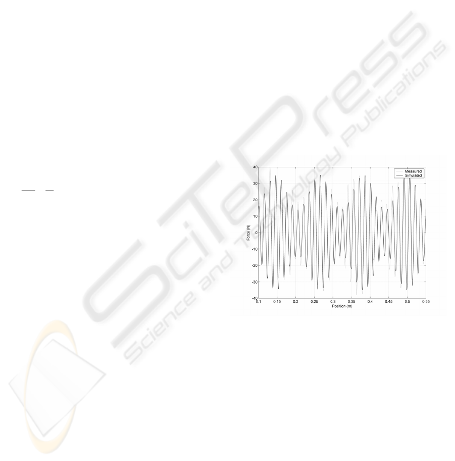
The force ripple can be described by sinusoidal
functions of the load position,
x, with a period of
ϕ
and an amplitude of
A
r
, i.e.,
sin( ) sin( )
11 12 2
F
AxAA x
ripple r r r
ϕϕ
⎡
⎤
=+
⎣
⎦
. (10)
In figure 3, the results of the simulation are
compared with those measured in the reference
system.
Figure 3: Comparison of measured and simulated
detent forces.
The reluctance force is another phenomenon that
occurs in linear synchronous motors. A lot of
research has been carried out into the reluctance in
linear induction machines, in which the phenomenon
depends on velocity. The reluctance force in
PMLSMs has been studied to a lesser extent. The
reluctance force is due to the variations in the self-
inductance of the windings with respect to the
relative position between the mover and the magnets
(Tan
et al., 2002). The reluctance force was
observed to be relatively small in the reference
system and, therefore, has not been included in the
model.
The model also takes into account the effect of
FORCE RIPPLE COMPENSATOR FOR A VECTOR CONTROLLED PM LINEAR SYNCHRONOUS MOTOR
179

friction. Friction is very important for control
engineering, for example, in the design of drive
systems, high-precision servomechanisms, robots,
pneumatic and hydraulic systems and anti-lock
brakes for cars. Friction is highly nonlinear and may
result in steady-state errors, limit cycles and poor
performance (Olsson
et al., 1998). Friction was
modeled using the simple gradient method in which
the linear motor system was set in a tilted position
and the moving part allowed to slide down freely.
Friction was measured at several tilt angles and the
results obtained were used to plot the friction
function as a function of speed. The friction model
took into account the Coulomb (static) and viscous
(dynamic) components
()
()FsignvF absvF
coulomb viscous
µ
⎡⎤
=+
⎣⎦
, (11)
where
v is the velocity of the motor. The friction
function was incorporated into the simulation model
in such a way that it acts between the stator and the
mover. In the simulation, the smoothing of the
friction function was used to obtain a numerically
efficient model in order to improve simulation rate.
The effect of load variation was also taken into
consideration. This was carried out using a forced
vibrating non-homogenous two-mass model, where
the load force variation
∆F
l
is calculated using a
spring-mass equation, which is the sum of the spring
force,
F
s
, and the damping force, F
d
. The equation of
motion for such a system is
()()
12 12 22
F
FF kxx cxx mx
lsd
∆= + = − + − =
&& &&
,(12)
where
k is the spring constant, c the damping
coefficient, and
i
x ,
i
x
&
and
i
x
&&
are the displacement,
velocity and acceleration of masses
m
i
, respectively.
The total disturbance force equation can be
described using the equations of detent force,
friction force and load force variation; i.e., the
disturbance force,
F
dist
, is
F
FFF
dist ripple l
µ
=++∆ (13)
This resultant disturbance force component is
added to the electromotive force to influence the
dynamical behavior of the linear motor system.
2.3 Current Controller of the Linear
Motor
The current control of the system is implemented in
the form of vector control. Vector control is based
on the space vector theory of electrical machines
and, therefore, can be easily implemented in the
motor model that is also based on the space vector
theory. Vector control is suitable for the force
(torque) control of both induction and synchronous
motors. Generally in the vector control theory, the
force and flux components are analyzed separately
from the motor currents using the mathematical
model of the machine, and control algorithms
control these components separately. In the vector
control used in this study, the direct axis current,
i
ad
,
is set to zero (
i
ad
=0) assuming that it does not
influence the generation of force; i.e. equation (9)
transforms to
()
F
i
dx d aq
π
ψ
τ
=
. (14)
This means that angle
ψ
, between the armature
current and q-axis, always remains at 0
° and that the
thrust is proportional to the armature current,
i
a
=i
aq
.
The drawback of vector control is its low robustness
for changes in the machine parameters. The
resistance values change considerably due to
temperature variations, and the inductances rapidly
reach their saturation levels. However, a vector
controller is appropriate for applications in which
good dynamics and/or accurate velocity control is
needed.
In literature, vector control is presented in many
ways. In this study, we have used a simulation
principle in which the incoming thrust command,
F*, is converted to the i
q
current component by
dividing the force value by the force constant of the
motor,
K
m
. The current control algorithms are
executed in the rotor flux coordinates and the
outputs of the controllers are transformed back into
the stator reference frame, and these values,
u
sa
, u
sb
,
and
u
sc
, are the inputs of the control inverter. In the
simulation model, the modulation technique used is
sinusoidal pulse width modulation (SPWM) with
ideal switches.
2.4 Verification of the Simulation
Model
The simulation model was implemented and
analyzed in the MatLab/Simulink
® software using
the previously mentioned equations. The PWM
ICINCO 2004 - ROBOTICS AND AUTOMATION
180
inverter is modeled as an ideal voltage source and
common Simulink blocks are used for the model.
The time step of the integrator in the analysis was 10
µs, except for the velocity controller, which had a
time step of 1 ms. The parameters used in the
simulation are introduced in table I in the appendix.
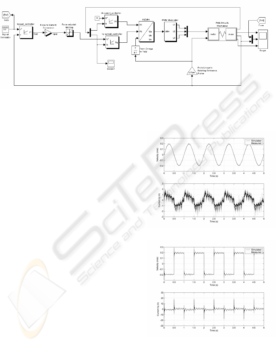
Figure 4 shows the Simulink model of the system.
The simulation results were compared with those
measured in the reference system. The motor studied
in this paper is a commercial three-phase linear
synchronous motor application with a rated force of
675 N. The moving part is set up on an aluminum
base with four recirculating roller bearing blocks on
steel rails. The position of the linear motor was
measured using an optical linear encoder with a
resolution of approximately one micrometer. The
parameters of the linear motor are given in table II in
the appendix.
The spring-mass mechanism was built on a tool
base in order to act as a flexible tool (for example, a
picker that increases the level of excitation). The
mechanism consists of a moving mass, which can be
altered in order to change the natural frequency of
the mechanism and a break spring, which is
connected to the moving mass on the guide. The
purpose of the mechanism is to increase the level of
excitation when the motor’s vibrational frequency is
equal to the mechanism’s natural frequency, which
was calculated at being 9.1 Hz for a mass of 4 kg.
The motion of the moving mass was measured using
an accelerometer.
The physical linear motor application was driven
in such a way that the PI velocity controller was
implemented in Simulink to gain the desired velocity
reference. The derived algorithm was transferred to
C code for dSpace’s digital signal processor (DSP)
to use in real-time. The force command, F*, was fed
into the drive of the linear motor using a DS1103
I/O card. The computational time step for the
velocity controller was 1 ms, while the current
controller cycle was 31.25
µs. The measured and
simulated velocity responses and force generating
quadrature currents are compared in figure 5. Sine
and step functions were used as the reference
velocity.
(a)
(b)
Figure 5: A comparison of the measured and
simulated quadrature currents and velocity responses in
the case of (a) a sine velocity reference and (b) a step
velocity reference.
Fi
g
ure 4: The Simulink model of the motor s
y
stem.
FORCE RIPPLE COMPENSATOR FOR A VECTOR CONTROLLED PM LINEAR SYNCHRONOUS MOTOR
181
3 DISTURBANCE
COMPENSATION
Disturbance compensation is applied to the motor
model to reduce a detrimental force ripple. Force
ripple compensation improves the speed response
and robustness of the system. The force ripple, i.e.
the detent force, friction, and load variation, is
estimated using a disturbance observer, or in other
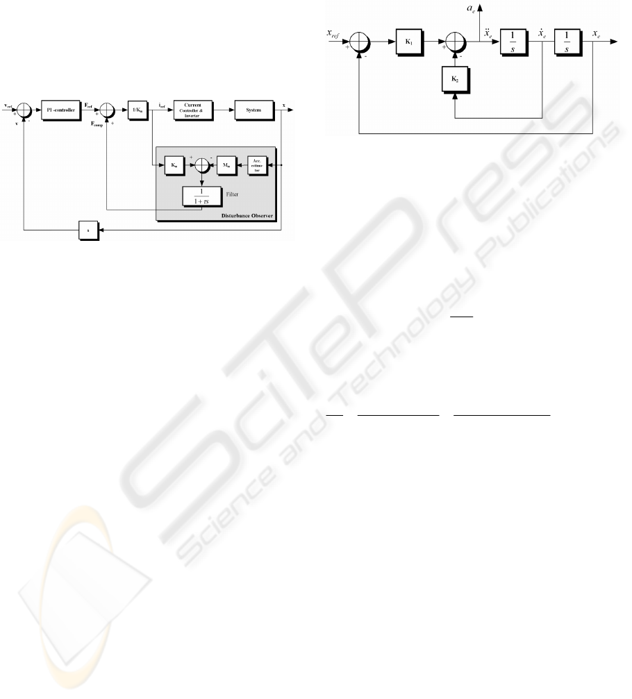
words, a load force observer. Figure 6 shows the
construction of the compensator.
Figure 6: Disturbance compensation scheme utilizing
load force estimation.
The concept of the observer is based on the
comparison of the actual input force with the ideal
one. This gives rise to an error, which after proper
filtering, is used to produce the compensation
current,
i
comp
. The filter implemented in this study is
a second-order Butterworth digital low-pass filter
with a cut off frequency of 50 Hz. The main function
of the filter is to reduce high-frequency noise due to
input signal derivation but also break the algebraic
loop in the simulation model between the currents
i
ref
and i
comp
. Unfortunately, the time delay of the
filter also limits the performance of robust control,
since it delays the estimated force disturbance
(Godler
et al., 1999); therefore, the cut-off
frequency should be as high as possible. Hong et al.
(1998) suggested that an artificial delay be used in
the filtering bath of the observer in order to improve
dynamic behavior.
The limitations of this method are highlighted by
the fact that acceleration, which is needed in the
disturbance observer, is generally not available.
Usually, acceleration is calculated as the time
derivative of the output of the pulse encoder,
although the signal becomes easily erroneous due to
the high noise ratio in the encoder signal, and the
filtering of this kind of signal increases the
undesirable time delay, which leads to an unstable
response. In this study, acceleration is estimated
using an acceleration estimator, which is based on
the construction introduced in (Lee
et al., 2001).
This so-called low-acceleration estimator is based on
the fact that the displacement signal from the
encoder is accurate and numerical integration
provides more stable and accurate results than does
numerical differentiation. Figure 7 shows the
structure of the accelerated estimator.
Figure 7: Structure of low-acceleration estimator.
The estimation of acceleration,
a
e
, is calculated
from the displacement signal,
x, of the encoder using
a double integrator. The estimator takes the form of
a PD controller, in which the estimated
displacement,
x
e
, is set to follow the actual
displacement,
x; i.e. the acceleration estimate is
()
12
dx
e
aKxx K
ee
dt
=−−
(15)
and the transfer function from
x to x
e
is
2
1
222
2
21
x
K
eb
x
sKsK s s
bb
ω
ζ
ωω
==
++ + +
, (16)
where
ω
b
represents the bandwidth of the
acceleration estimator and
ζ
is the damping ratio.
Gains
K
1
and K
2
from the PD controller can be
determined from the required bandwidth of the
estimator. Lee
et al. (2001) propose that a good
guideline for the damping ratio is 0.707, which
corresponds to critical damping.
The proposed disturbance regulator has been
tested in the simulation model introduced earlier and
implemented in the physical application. The
algorithm of the controller was run in real-time with
a frequency of 1 kHz. The damping ratio of the
acceleration estimator,
ζ
, was 0.707 and the
bandwidth
ω
b
1000 Hz, i.e. the gains are K
1
=10e
5
and
K
2
=1414. Figure 8 shows a comparison of the
velocity errors between the reference and actual
velocities in compensated and non-compensated
systems, when the amplitude of the reference
velocity sine signal was 0.1 m/s.
ICINCO 2004 - ROBOTICS AND AUTOMATION
182
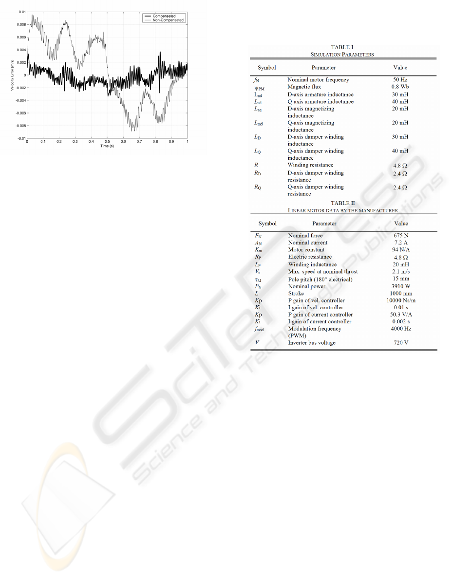
Figure 8: The error between the actual and reference
velocities in the compensated and non-compensated
systems, when the reference velocity signal is sine with an
amplitude of 0.1 m/s.
4 CONCLUSION
This paper presented and verified a dynamic model
for a PMLSM including non-idealities. The model
appeared to be an effective tool for designing the
controller of such a system. A disturbance estimator,
which included a low-acceleration estimator, was
proposed and successfully implemented in the
control of the motor. By means of an accurate
simulation model, it was possible to design and test
the controller without fear of physical damage. The
implementation of the proposed controller was
easily carried out by using a DSP system that
supported the used simulation software. Preliminary
parameter tuning was performed by using the
simulation model and final tuning was carried out in
the physical linear motor application.
It was observed that mechanical non-idealities
have important effect on the dynamics of the motor
system. This effect can be reduced by constructional
modifications and/or a suitable control algorithm. As
mentioned before, the acceleration signal for
disturbance estimation or another control algorithm
is not usually available. The double derivation of the
encoder signal produces a very noisy signal, and
filtering this kind of signal leads to undesirable
stability problems. With the proposed method,
acceleration can easily be estimated from the
position signal.
APPENDIX
REFERENCES
Bassi, E., Benzi, F., Buja, G. and Moro, F., 1999. “Force
disturbance compensation for an A.C. brushless linear
motor,” in Conf. Rec. ISIE’99, Bled, Slovenia, 1999,
pp.1350-1354.
Castillo-Castaneda, E. and Okazaki, Y., 2001. ”Static
friction compensation approach to improve motion
accuracy of machine tool linear stages,”
Instrumentation and development, vol. 5, no. 1, March
2001.
Chun, J.-S., Jung, H.-K. and Jung, J.-S., 2000. “Analysis
of the end-effect of permanent magnet linear
synchronous motor energized by partially exited
primary,” ICEM, International Conference on
Electrical Machines, Espoo, Finland, vol. 1, pp. 333-
337, 2000.
Deur, J. and Peric, N., 2000. ”A Comparative study of
servosystems with acceleration feedback,” IEEE Ind.
Applicat. Conf., Italy, 2000, pp. 1533-1540.
Godler, I., Inoue, M. and Ninomiya, T., 1999. “Robustness
comparison of control schemes with disturbance
FORCE RIPPLE COMPENSATOR FOR A VECTOR CONTROLLED PM LINEAR SYNCHRONOUS MOTOR
183

observer and with acceleration control loop,” in Conf.
Rec. ISIE’99, Slovenia, 1999, pp.1035-1040.
Gieras, J. F. and Piech, Z. J., 2001. Linear Synchronous
Motors: Transportation and Automation Systems. Boca
Raton, USA: CRC, 2001.
Hong, K. and Nam, K., 1998. ”A Load torque
compensation scheme under the speed measurement
delay,” IEEE Trans. Ind. Electron., vol. 4, no. 2, April
1998.
Hor, P. J., Zhu., Z. Q., Howe, D. and Rees-Jones, J.,
1998. “Minimization of cogging force in a linear
permanent magnet motor”, IEEE Trans. Magn., vol.
34, no. 5, pp. 3544-3547, Sept. 1998.
Hyun, D.-S., Jung, I.-S., Shim, J.-H. and Yoon, S.-B.,
1999. “Analysis of forces in a short primary type
permanent magnet linear synchronous motor,” IEEE
Trans. Energy Conversion, vol. 14, no. 4, pp. 1265-
1270, 1999.
Inoue, M. and Sato, K., 2000. “An approach to a suitable
stator length for minimizing the detent force of
permanent magnet linear synchronous motors,” IEEE
Trans. Magn., vol. 36, no. 4, pp. 1890-1893, July 2000.
Jung, S.-Y. and Jung, H.-K., 2002. ”Reduction of force
ripples in permanent magnet linear synchronous
motor,” Proceeding of International Conference on
Electrical Machines, Brugge, Belgium pp.452, Aug
2002.
Kim, B. K., Chung, W. K. and Oh, S. R., 2002.
“Disturbance Observer Based Approach to the Design
of Sliding Mode Controller for High Performance
Positioning Systems,” 15th IFAC World Congress on
Automatic Control, 2002.
Lee, S.-H. and Song, J.-B., 2001. “Acceleration estimator
for low-velocity and low-acceleration regions based on
encoder position data,” IEEE/ASME Trans.
Mechatron., vol. 6, no. 1, March 2001.
Morimoto, S., Sanada, M. and Takeda, Y., 1997. “Interior
Permanent Magnet Synchronous Motor for High
Performance Drives,” IEEE Trans. Ind. Applicat., vol.
33, Issue 4, July-Aug. 1997.
Olsson, H., Åström, K. J., de Wit, C. C., Gäfvert, M. and
Olsson, P. L., 1998. “Friction Models and Friction
Compensation,” European Journal of Control, 1998,
Vol.4, No.3.
Otten, G., de Vries, T.J.A., van Amorengen, J., Rankers,
A.M. and Gaal, E.W., 1997. “Linear motor motion
control using a learning feedforward controller,”
IEEE/ASME Trans. Mechatron., vol. 2, no. 3, pp. 179-
187, 1997.
Tan, K. K., Huang, S. N. and Lee, T. H., 2002. ”Robust
adaptive numerical compensation for friction and force
ripple in permanent-magnet linear motors,” IEEE
Trans. Magn., vol. 38, no. 1, January 2002.
Zhu, Z. Q., Xia, Z. P., Howe, D. and Mellor, P. H., 1997.
“Reduction of cogging force in slotless linear
permanent magnet motors”, Proc.IEEE Electr. Power
Appl., vol. 144, no. 4, pp. 277-282, July 1997.
ICINCO 2004 - ROBOTICS AND AUTOMATION
184
