
PREDICTED POLAR MAPPING FOR MOVING OBSTACLE
DETECTION
Young–Joong Kim
Beom–Soo Kim
Myo–Taeg Lim
School of Electrical Engineering, Korea University
1 Ga Anam-dong, Sungbuk-ku, Seoul, Korea 136-701
Keywords:
Computer vision, obstacle detection, polar mapping, optical flow, vision-based robot
Abstract:
This paper presents the predicted polar mapping that is to improve the efficiency of an unexpected moving
obstacle detecting system in a single vision-based robot. The polar mapping is used to simplify the segmenta-
tion of moving objects from the background and is performed with the focus of expansion (FOE) as the center.
When the movement of the robot per a step becomes a bit large, then static objects or background are detected
as moving objects. Thus, the velocity of the robot becomes so slow. Therefore, to enlarge the movement of
the robot and to improve this system, we propose the predicted polar mapping that predicts the polar mapped
image after robot moves to be admissible. In order to verify experimentally our proposed procedure, we make
several comparative tests in the corridor.
1 INTRODUCTION
Vision systems are used more and more for the nav-
igation of mobile robot because visual sensing can
provide the robot with an incredible amount of in-
formation about its environment. One of the central
problems of vision-based navigation is moving ob-
stacle avoidance. Many approaches have been taken
to solve the problems of moving obstacle avoidance
and a wide variety of approaches and algorithms were
researched in this field (Bhaunu, 1988), (Thompson,
1988). One of the key issues is differentiating non-
stationary objects from the stationary background in
a moving platform, since both the background and
the object appear to be moving (Frazier, 1992), (Nair,
1994), (Nair, 1998).
The algorithms for detecting moving objects from
a moving platform compute the global optical flow
(Enkelmann, 1996). Other algorithms use image
transformations and qualitative analysis of the motion
of points to detect and segment the moving objects
(Bhaunu, 1988), (Nair, 1994), (Nair, 1998). These
methods are typically more effective in the purpose to
get information about the detected motion of a robot.
In these methods, the camera provides the global in-
formation on the working environment, so that it can
separate the moving and static objects without chang-
ing its pose by finding the difference of two consec-
utive images. A more sophisticated method is to find
the optical flow using two consecutive polar map-
ping images (Nair, 1994), (Nair, 1998), (Enkelmann,
1996).
In this paper, we present a procedure using the pre-
dicted polar mapping and the segmentation to detect
unexpected moving objects that appear in the path of
a navigating robot and to estimate the relative motion
of the object with respect to the robot. After qualita-
tive detection of the moving obstacles, relative mo-
tion information of the object is obtained by com-
puting the time-to-impact between the robot and the
obstacles (Tistarelli, 1991), (Tistarelli, 1993). Since
this method requires the determination of correspon-
dences between all pixels in the image, the computa-
tional cost and error rate are very high. Therefore, by
the help of the method in (Nair, 1994), (Nair, 1998),
moving objects are segmented from image for effec-
tive use of this method or less computation. But, it has
the terrible limitation as follows. If the movement of
robot increase, then the static objects or background
is detected as moving objects. Thus, we use the im-
age that is acquired after very small movement. As
a consequence, the velocity of robot becomes slow.
Therefore, to improve the efficiency of this method,
we proposed the predicted polar mapping that pre-
dicts the polar mapped image after robot moves to be
admissible.
421
Kim Y., Kim B. and Lim M. (2004).
PREDICTED POLAR MAPPING FOR MOVING OBSTACLE DETECTION.
In Proceedings of the First International Conference on Informatics in Control, Automation and Robotics, pages 421-424
DOI: 10.5220/0001127904210424
Copyright
c
SciTePress
2 PREDICTED POLAR MAPPING
To segment moving object from the background, each
image acquired by the robot is transformed from
Cartesian coordinates to polar coordinates, using a
polar mapping that transforms the image to a polar
coordinate system with the focus of expansion (FOE)
as the center. The image is transformed to polar coor-
dinates using the following equations.
ρ =
p
(x − x
F OE
)
2
+ (y − y
F OE
)
2
(1)
η = tan
−1
(x − x
F OE
)
(y − y
F OE
)
(2)
In the above equations, ρ is the radial distance from
the FOE to the Cartesian image coordinate (x, y),
and η represents the angle 0 ∼ π subtended by the
Cartesian image coordinates (x, y), the FOE, and the
Cartesian image coordinates (1, 0). The advantages
of using the polar and the log-polar or complex loga-
rithmic mapping (CLM) have been shown in (Bishay,
1994), (Tistarelli, 1993). Two successive images
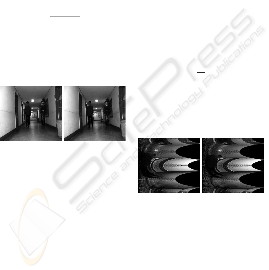
(a) (b)
Figure 1: (a) The first image with moving forward of a robot
= 0. (b) The second image with moving forward of a robot
= 3cm.
from a typical sequence in a corridor are shown in
Fig.1. When this transformed image is represented
with radial, ρ, and angular, η, axis as the Cartesian
coordinates, the motion of the stationary objects
will be in the horizontal direction. Objects that are
moving with respect to the observer will have motion
in an angular direction in this transformed space. To
perform the polar mapping, the FOE must be located
accurately. For the experiments presented in this
paper the FOE is determined using the vision-based
algorithm described in (Frazier, 1992).
For the system that detects unexpected moving
objects that appear in the path of a navigating robot,
the difference image between the first image and
the second image after robot moves is used. In this
detecting system, if the movement of robot per step
become a bit large, then the static objects or back-
ground is detected as moving object. Thus, we use
the difference image after robot moves very small.
As a consequence, the velocity of robot becomes
so slow. Therefore, for more large movement of
robot, we predict the polar mapping image after
robot moves to be admissible. The followings are the
procedure of the predicted polar mapping.
Procedure 1: The predicted polar mapping
A. Acquire an image from camera.
B. Execute polar mapping of the image.
C. Compute the optical flow with respect to movement
of robot.
D. Compute the zooming rate.
E. Enlarge the polar mapping image with zooming
rate horizontally. (i.e., Enlarge the radial axis of the
polar mapping image with zooming rate.)
F. Cut off the end part of radial axis of the polar
mapping image with zooming rate. (i.e., Cut off the
right end part of the polar mapping image.)
The zooming rate used in procedure 1 is defined as
follows:
α =
W
ρ
H
(3)
where α is a zooming rate, W
ρ
is a radial component
of the optical flow, which is described in (Tistarelli,
1991), (Tistarelli, 1993) and H is the size of horizon-
tal axis (i.e., radial, ρ, axis). The (a) in Fig.2 is the
resultant image from procedure 1 that is the predicted
polar mapping of the first image, and the (b) in Fig.2
is general polar mapping of the second image that is
acquired after robot moves forward at 3cm.
(a) (b)
Figure 2: (a) The predicted polar mapping of (a) in Fig.1.
(b) The polar mapping of (b) in Fig.1.
3 DETECTING VERTICAL
MOTION
After transforming the image into the predicted polar
mapping, the problem of detecting a moving obsta-
cle is to find vertical motion along an angular axis
in sequence of transformed images. If a horizontal
edge in an image moves horizontally, then the over-
lap between the edge from one image to the next im-
age is very large. On the other hand, if a horizontal
ICINCO 2004 - ROBOTICS AND AUTOMATION
422
edge moves vertically, then there is very little over-
lap. Hence, the qualitative measure of the motion
is obtained by detecting the vertical motion of edges
present in the transformed image. In this paper, we
use the Sobel operator presented in (Gonzalez, 1992),
(Forsyth, 2003) to detect edges from each image. The
(a) in Fig.3 shows the edge detected images of the pre-
dicted polar mapping (i.e., (a) in Fig.2), and the (b) in
Fig.3 shows the edge detected images of the general
polar mapping (i.e., (b) in Fig.2). A qualitative es-
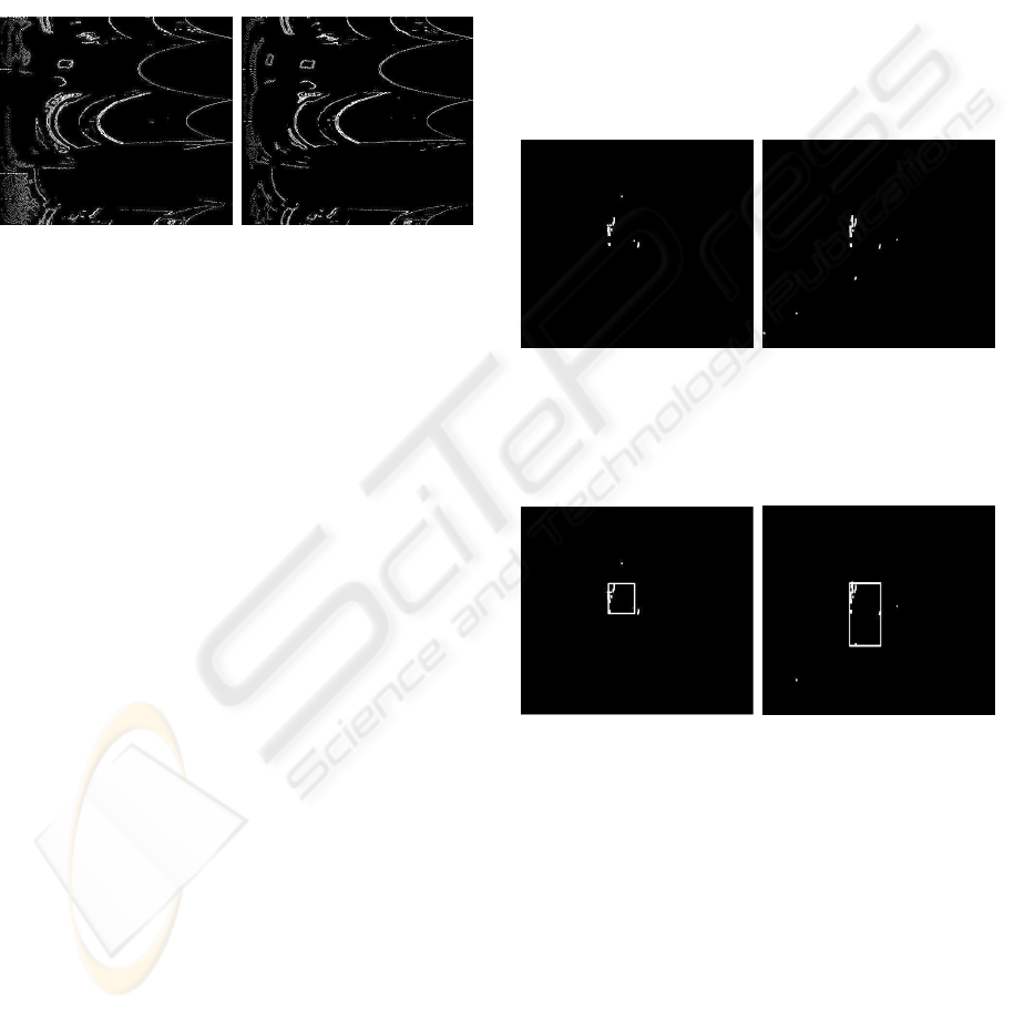
(a) (b)
Figure 3: (a) The edges detected image of (a) in Fig.2. (b)
The edges detected image of (b) in Fig.2.
timate (reported in (Nair, 1994), (Nair, 1998)) of the
motion of the object in these images is obtained as fol-
lows. First, horizontal and angular edges in the trans-
formed images are enhanced. Let I
(p)
sobel
and I
(n)
sobel
represent the edge images of predicted polar mapping
and second polar mapping obtained by Sobel opera-
tor, respectively. Then, the resultant image I
det
that
detects moving objects is obtained as following equa-
tion.
I
det
= I
(p)
sobel
· I
(p)
sobel
− I
(p)
sobel
· I
(n)
sobel
(4)
In above equation, we can enlarge the positive val-
ues along horizontal edge components of each image
using multiplication. Edges that move vertically pro-
duce little overlap, so they are eliminated. Hence, (4)
is a map of all horizontal and angular edges that have
moved vertically. Some edges that have moved hor-
izontally may be present in this resultant image, but
they are usually small pieces. Actually, this map con-
tains small pieces of horizontally moving edges that
did not completely cancel out. In practice, however,
these small pieces are very weak, and are filtered out
by a thresholding process (Gonzalez, 1992), (Forsyth,
2003). As a consequence, this map, I
det
, contains the
detected motion. Next, this map is transformed back
into the rectangular frame. In order to compute the
optical flow, rather than use the qualitative motion de-
tected entire image, the segmentation can be used to
find the region where the moving object may be lo-
cated (i.e., the region of interest) in consecutive im-
ages.
In this paper, we use a region using a rectangular area
as the base template. A rectangular was chosen as the
shape that best represents the area occupied by the
moving object because in most cases, the moving ob-
jects in a man-made environment are in the forms of
people or opening doors (Nair, 1994), (Nair, 1998).
To obtain the regions that enclose the detected motion
pixels, general rectangular clustering method (Gon-
zalez, 1992), (Forsyth, 2003) is used. In using this
method, to reduce errors or disturbance, we discard
the detected pixels that are the most outer of each side
as Fig.5. The (a) in Fig.4 shows the resultant image
that is transformation of the motion detected image
using the predicted polar mapping back into rectan-
gular coordinates, and the (b) in Fig.4 is the restored
motion detected image using the general polar map-
ping. Fig.5 is segmentation of Fig.4, respectively.
(a) (b)
Figure 4: (a) The restored motion detected image of the
predicted polar mapping. (b) The restored motion detected
image of the general polar mapping.
(a) (b)
Figure 5: (a) The segmented image of (a) in Fig.4. (b) The
segmented image of (b) in Fig.4.
To verify our proposed method that is predicted po-
lar mapping, we make the simple comparative test. In
this test, we make a robot move at 9cm for compar-
ison of the predicted polar mapping with the general
polar mapping. The results of this test are shown in
Fig.6, and we see that the result of the polar mapping
has great noise as compared with the predicted polar
mapping. It is obvious that the general polar mapping
is not suitable to the system that needs a little more
movement of robot. As a consequence, our proposed
method can be of help to detect a moving object. In
addition, The optical flow can be obtained by the help
of (Tistarelli, 1991), (Tistarelli, 1993).
PREDICTED POLAR MAPPING FOR MOVING OBSTACLE DETECTION
423
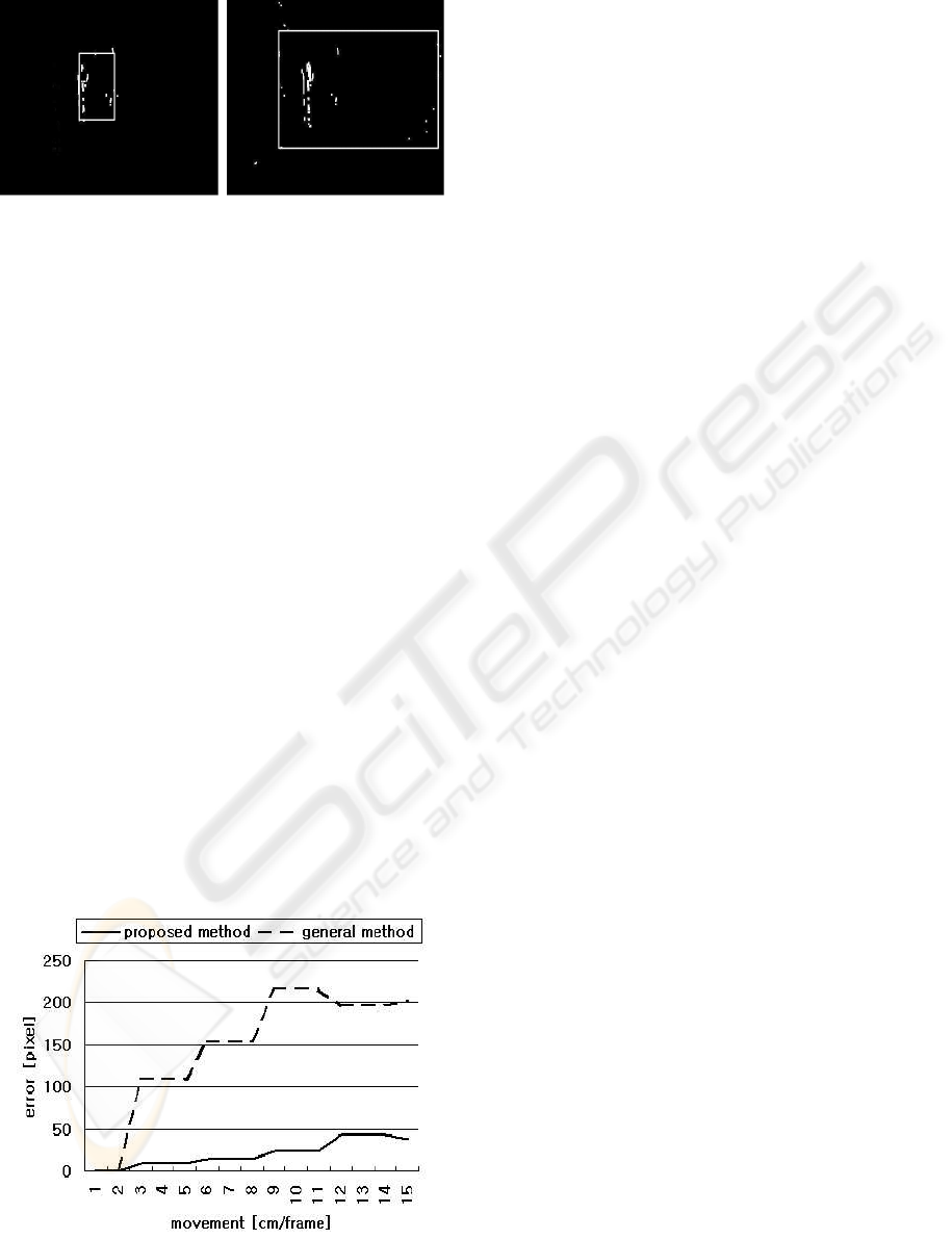
(a) (b)
Figure 6: (a) The segmented image using the predicted po-
lar mapping with moving forward of a robot = 9cm. (b) The
the segmented image using the polar mapping with moving
forward of a robot = 9cm.
4 EXPERIMENTAL RESULTS
The moving object detecting system using the pro-
posed method was implemented on the Pioneer 2–
AT mobile robot of ActivMedia. The main control
processor of this robot is a Simens 88C166(20MHz)
microprocessor. For image processing and control of
the robot, a industrial computer with Intel Pentium
III(850MHz) and Windows 98, a Panasonic CCD
camera, and frame grabber (DataTranslation DT3132)
are mounted on the robot. The images have been ac-
quired at a resolution of 480×360 pixels. The optical
axis of the camera is almost parallel to the ground. In
order to verify experimentally the proposed method
outlined in procedures 1, we make several compara-
tive tests in the corridor. We make a robot move at
3cm to 15cm for comparison of the predicted polar
mapping with the general polar mapping. The results
are shown in Fig.7, and we see that the polar map-
ping has great noise as compared with the predicted
polar mapping. Hence, the predicted polar mapping
is robustly admissible to the system that needs a little
more movement of robot.
Figure 7: Errors of the optical flow in comparative test
5 CONCLUSION
In this paper, the procedure using the predicted polar
mapping and the segmentation to detect unexpected
moving objects has been presented, and has been im-
plemented with a Pioneer 2–AT mobile robot. In or-
der to enlarge movement of robot per a step and im-
prove the effective use of polar mapping, we have pro-
posed the procedure that predicts the polar mapping
image after robot moves to be admissible. To ver-
ify experimentally our proposed procedure, we make
several comparative tests in the corridor. It is obvi-
ous the predicted polar mapping has a little noise as
compared with the polar mapping.
REFERENCES
Bhaunu, B. (1988). Qualitative motion detection and track-
ing of targets from a mobile platform. In DARPA Im-
age Understanding Workshop, Cambridge, MA. pp.
289–313.
Bishay, M. (1994). Object detection in indoor scenes using
log-polar mapping. In IEEE International Conference
on Robotics and Automation. 1, pp. 775–780.
Enkelmann, R. (1996). An experimental inverstigation of
estimation approaches for optical flow field. In Motion
Understanding: Robot and Human Vision. 6, pp 189–
226.
Forsyth, A. (2003). Digital Image Processing. Prince Hall,
Pearson Education.
Frazier, J. (1992). Detecting moving objects from a mov-
ing platform. In Proceedings of IEEE International
Conference on Robotics and Automation. 2, pp. 1627–
1633.
Gonzalez, C. (1992). Digital Image Processing. Addiison–
Wesley.
Nair, D. (1994). Detecting unexpected moving obstacles
that appear in the path of a navigating robot. In IEEE
International Conference on Image Processing. 2, pp.
311–315.
Nair, D. (1998). Moving obstacle detection from a navi-
gating robot. In IEEE Transactions on Robotics and
Automation. 8, pp. 39–57.
Thompson, W. (1988). Detecting moving objects. In Int. J.
Computer Vision. 8, pp. 39–57.
Tistarelli, M. (1991). Direct estimation of time-to-impact
from optical flow. In IEEE Workshop on Visual Mo-
tion. Princeton, NJ, Oct. 7–9, pp. 226–233.
Tistarelli, M. (1993). On the advantages of polar and log-
polar mapping for direct estimation of time-to-impact
from optical flow. In IEEE Transactions on Pattern
Analysis and Machine Intelligence. 15, pp. 401–410.
ICINCO 2004 - ROBOTICS AND AUTOMATION
424
