
Towards Automated Analysis of Model-Driven Artifacts in Industry
Ramon Schiffelers
1,2
, Yaping Luo
2,3
, Josh Mengerink
2
and Mark van den Brand
2
1
ASML N.V., Veldhoven, The Netherlands
2
Department of Mathematics and Computer Science, Eindhoven University of Technology, The Netherlands
3
Altran Netherlands B.V., Eindhoven, The Netherlands
Keywords:
Model-Driven Engineering, Domain-Specific Languages, MDSE Ecosystems, Evolution.
Abstract:
Developing complex (sub)systems is a multi-disciplinary activity resulting in several, complementary models,
possibly on different abstraction levels. The relations between all these models are usually loosely defined in
terms of informal documents. It is not uncommon that only till the moment of integration at implementation
level, shortcomings or misunderstanding between the different disciplines is revealed. In order to keep models
consistent and to reason about multiple models, the relations between models have to be formalized. Multi-
Disciplinary System Engineering (MDSE) ecosystems provide a means for this. These ecosystems formalize
the domain of interest using Domain Specific Languages (DSLs), and formalize the relations between models
by means of automated model transformations. This enables consistency checking between domain and aspect
models and facilitates multi-disciplinary analysis of the single (sub)system at hand. MDSE ecosystems provide
the means to analyze a single (sub)system model. A set of models of different (sub)systems can be analyzed
to derive best modeling practices and modeling patterns, and to measure whether a MDSE ecosystem fulfills
its needs. The MDSE ecosystem itself can be instrumented to analyze how the MDSE ecosystem is used in
practice. The evolution of models, DSLs and complete MDSE ecosystems is studied to identify and develop
means that support evolution at minimal costs while maintaining high quality. In this paper, we present the
anatomy of MDSE ecosystems with industrial examples, the ongoing work to enable the various types of
analysis, each with their dedicated purpose. We conclude with a number of future research directions.
1 INTRODUCTION
Developing complex (sub)systems is a multi-
disciplinary activity. Mechanical, electrical, and soft-
ware engineers develop their own models of the system
to analyze properties relevant within their discipline.
Within a single discipline, several models might be
developed on different abstraction levels. To reason
about (sub)system wide properties, one might need
information from multiple models that originate from
different disciplines. The relations between all these
models are usually loosely defined in terms of infor-
mal documents. It is only at the implementation level
where all artifacts resulting from the different disci-
plines come together in terms of hardware and soft-
ware artifacts, and the couplings between them become
explicit. It is not uncommon that only on this imple-
mentation level, shortcomings or misunderstanding
between the different disciplines is revealed. Even
more importantly, having these interdisciplinary re-
lations loosely defined on the model level limits the
ability to reason about the realization of system-wide
key performance indicators and trade-offs (throughput
versus accuracy) sufficiently early in the development
process.
In order to keep models consistent and to reason
about multiple models, the relations between models
have to be formalized. Tooling is needed to define,
validate and maintain these relations. As a first step
in this direction, ASML, the world’s leading provider
of complex lithography systems for the semiconductor
industry, is developing so-called Multi-Disciplinary
Systems Engineering (MDSE) ecosystems. Lithog-
raphy machines are highly complex Cyber-physical
Systems of Systems, designed to be extremely accu-
rate, provide very high throughput and operate 24/7
to deliver exceptionally reliable results. To keep up
with the increasing system performance, evolvabil-
ity and predictability requirements, ASML combines
state-of-the-art methods and techniques from academia
with state-of-the-practice in industry into these MDSE
ecosystems. In such ecosystem, concepts and knowl-
edge of the several involved disciplines is formalized
into of one or more domain specific languages (DSLs).
Schiffelers, R., Luo, Y., Mengerink, J. and Brand, M.
Towards Automated Analysis of Model-Driven Artifacts in Industry.
DOI: 10.5220/0006749407430751
In Proceedings of the 6th International Conference on Model-Driven Engineering and Software Development (MODELSWARD 2018), pages 743-751
ISBN: 978-989-758-283-7
Copyright © 2018 by SCITEPRESS – Science and Technology Publications, Lda. All rights reserved
743
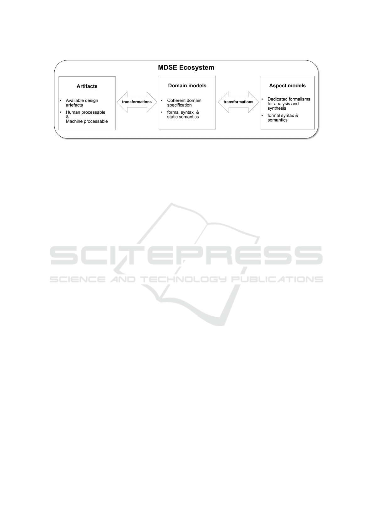
Figure 1: Anatomy of a MDSE Ecosystem.
Transformations between these languages formalize
the relations between them. In this way, such ecosys-
tem facilitates in clear and precise, unambiguous com-
munication between the different disciplines.
This paper presents current and future research
efforts, and their rationale, on model analysis, in par-
ticular in the context of Multi-Disciplinary Systems
Engineering (MDSE) ecosystems. To prevent what
happened in the software engineering domain, where
the growth of software complexity resulted in ever
increasing development and maintenance costs, we
•
propose several analysis techniques and directions
to ensure that proper MDSE ecosystems will be
developed that fulfill their needs sufficiently well;
•
analyze the evolution of models, DSLs and com-
plete MDSE ecosystems to identify and develop
means that support evolution at minimal costs
while maintaining high quality.
Outline.
The outline of this paper is as follows. In
Section 2, MDSE ecosystems are described and illus-
trated by means of examples. The different types of
analysis techniques and directions together with their
rationale are described in Section 3. A tool to support
(a subset of) the proposed analysis is described in Sec-
tion 4. Directions for future research are outlined in
Section 5.
2 MDSE ECOSYSTEMS
A Multi-Disciplinary Systems Engineering (MDSE)
ecosystem is an open/extendable set of seamlessly in-
teracting tools supporting engineers from different dis-
ciplines to develop complex systems. Its ingredients
as well as their rationale are described in Section 2.1.
Concrete examples taken from industry are described
in Section 2.2, and Section 2.3 describes the develop-
ment principles and vision of MDSE ecosystems.
2.1 Anatomy
A MDSE ecosystem consists of domain models, aspect
models, and automatic transformations between them,
see Figure 1. Many ecosystems are also equipped
with automated model-re-constructors to reuse already
existing artifacts from predecessor systems.
Domain Models.
The domain of interest is syntac-
tically formalized in terms of metamodels and Ob-
ject Constraint Language (Warmer and Kleppe, 2003)
(OCL) constraints. The domain metamodel contains
the relevant domain concepts with their relations and
those concepts and relations only. This avoids domain
encoding in an overly expressive language. Concrete
textual and/or graphical syntaxi are defined according
to the requirements and wishes that domain experts
have on them. This increases the understandability for
domain experts, and is crucial for the adoption of a
MDSE ecosystem in industry. Domain concepts hardly
need any (behavioral) semantical explanation for do-
main experts to be comfortable to work with; they
already know these concepts very well. Obviously, by
transforming domain models to aspect models, their
(behavioral) semantics are defined formally as well.
Aspect Models.
To analyze several different kinds
of properties, such as timing (worst/best case, stochas-
tic) and correctness (absence of deadlock), of a do-
main model, the domain model is transformed to sev-
eral aspect models. Each aspect models has its own
analysis purpose and dedicated tool associated with
it. Examples of typical analysis tools are simulators,
modelcheckers, or finite element analysis tools. The
analysis results are used for making key decisions or
for design validation. Another form of aspect models
are models from which implementation/realization ar-
tifacts are synthesized. Examples of synthesis tools
are codegenerators or 3D printers.
MOMA3N 2018 - Special Session on Model Management And Analytics
744

Each of these aspect tools have their own applica-
tion domain together with their strengths and weak-
nesses. Their combination is needed to develop high
complex systems. Often, one can observe that one of
the input languages of aspect tools is lifted to become
the specification language for some domain. However,
mostly, this is a suboptimal solution, as the domain
concepts are most likely encoded in terms of different
concepts that are relevant for the aspect only.
Artifacts and Reconstruction.
New high complex
systems are rarely developed from scratch, they rather
evolve from predecessor systems. The size and value
of the existing artifacts and the required time-to-market
constraints usually prevents a green-field approach for
modeling, e.g. modeling from scratch. This requires
an incremental introduction of an MDSE ecosystem in
an existing system development process. Automated
model reconstruction from existing artifacts enables a
gradual introduction of a MDSE ecosystem. Reusing
the artifacts from a predecessor system, the automated
model-re-constructors construct domain models from
them. These models can be adapted and modified to
develop the new system. Examples of such predefined
artifacts are source code, test cases, or models from
(software) versioning systems, or logging information
obtained from running systems.
Automated Transformations.
Automated transfor-
mations re-use conventions and invariants from the
domain. They formalize the relations between model-
s/languages, and ensure consistency between the vari-
ous models at hand. Their automation is indispensable
to obtain an efficient and effective development pro-
cess.
2.2 Examples of MDSE Ecosystems
As explained before, each MDSE ecosystem has its
own well defined application domain. Examples of
developed MDSE ecosystems are:
•
CARM 2G, application domain Process Control.
It enables mechatronic design engineers to de-
fine the application in terms of process (motion)
controllers (coupled with defacto standard Mat-
lab/Simulink, provides means for electronic en-
gineers to define the platform containing sensors,
actuators, the (multi-processor, multi-core) com-
putation platform and the communication network,
and means for software engineers to develop an
optimal mapping of the application on to the plat-
form, see (Schiffelers et al., 2012; Adyanthaya,
2016);
•
ASOME, application domain software. It enables
functional engineers (from different disciplines)
to define data structure and algorithms, and pro-
vides software engineers to define supervisory con-
trollers and data repositories (Alberts, 2016);
•
WLSAT, application domain Manufacturing Logis-
tics. It provides a formal modeling approach for
compositional specification of both functionality
and timing of manufacturing systems. The per-
formance of the controller can be analyzed and
optimized by taking into account the timing char-
acteristics. Since formal semantics are given in
terms of a (max, +) state space, various existing
performance analysis techniques can be reused.
(van der Sanden et al., 2015);
•
MIDS, application domain Model Inference from
(legacy) Software. It enables software engineers to
infer models capturing the behavior of the software
by integrating techniques for source code analysis,
active learning and passive learning (Schiffelers,
2017);
•
T-iPPS, application domain Performance Analy-
sis of (large-scale) Software. It provides software
execution architects to monitor and dimension the
computing and communication (network) platform
that executes the software applications of a TWIN-
SCAN machine. Furthermore, it supports product
architects to diagnose anomalies in the run-time
behavior of a TWINSCAN machine;
•
CIF, application domain Supervisory Controller
Synthesis. It provides means to develop supervi-
sory controllers by modeling the uncontrolled plant
behavior and the requirements in terms of automata
(untimed). The resulting supervisor is synthesized
automatically and by construction guaranteed to be
deadlock free. By means of simulation, the timed
behavior can be analyzed and visualized (van Beek
et al., 2014).
2.3 Vision of MDSE Ecosystems
Positioning the use of MDSE ecosystems w.r.t. the
ideation, externalization and production phases of
systems engineering, MDSE ecosystems facilitate un-
ambiguous communication during the externalization
phase, and bridge the gap between the externalization
and production phases for its particular application
domain. There is less focus on supporting the ideation
phase since new high tech systems usually evolve from
existing systems and are rarely developed from scratch.
Development Process.
Figure 2 shows the three
main processes. A system runs/executes in the pri-
Towards Automated Analysis of Model-Driven Artifacts in Industry
745
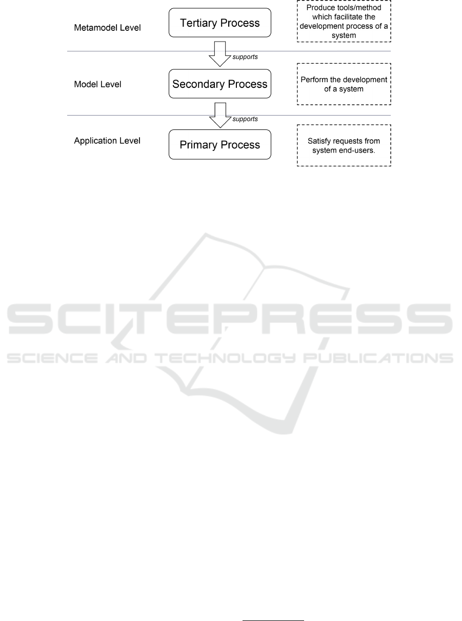
Figure 2: The relations of primary process, secondary process, and tertiary process.
mary process to satisfy the user requests of the system.
For example, a TWINSCAN machine exposes wafers
for end-users. The development of such (TWINSCAN)
system is done in a secondary process by practitioners.
Finally in the tertiary process, tools or methods which
facilitate the (TWINSCAN) system development pro-
cess are developed by toolsmiths; e.g. toolsmiths de-
velop development tools for practitioners.
MDSE ecosystems raise the level of abstraction
towards the functional level and the generation of code
artifacts reduces the need for software engineers (prac-
titioners) in the secondary process. Software engineers
will move from contributing to the secondary process
towards the tertiary process, and become toolsmiths.
For software engineers that remain contributing in the
secondary process, the time formerly spend at code
level can now be spend on thinking about the design
and analyzing it automatically on the model level, be-
fore generating the code automatically.
Formally Defined (Language) Interfaces.
MDSE
ecosystems are and should be extendable. The meta-
models are external interfaces of a MDSE ecosystem.
They formalize the data/information that can be ex-
changed and are used to formally define model-to-
model transformations to other ecosystems to facili-
tate unambiguous model exchange. In practice, lots of
efforts are spend on integrating different tools to facil-
itate some form of model exchange. While for some
disciplines, this is very well established, e.g. CAD/-
CAM coupling in the mechanical engineering domain,
for some disciplines this is still a laborious task involv-
ing developing parsers and encoding transformations
in a general purpose language, whereas the model re-
lations are despite being implemented and automated,
still not formally defined. Related work in this direc-
tion is megamodeling, as proposed in (Diskin et al.,
2013). Megamodeling aims to make the meaning of
relations among the models explicit as well.
Prepared for Evolution.
As explained before, in
practice the development of MDSE ecosystems starts
small; a narrow domain will be addressed offering lim-
ited functionality. Over time, the ecosystem grows,
see (Favre, 2005). Growth can be in different direc-
tions, e.g. addressing a larger application domain, or
the increase of functionality/use of models for analy-
sis or (artifact) synthesis. In this respect, Lehman’s
laws (Lehman, 1980) for software engineering also
hold for MDSE ecosystems.
DSLs in MDSE ecosystems are a hotspot-by-
design, e.g., many artifacts such as editors are gen-
erated from them. DSLs are strongly related with
each other by means of model transformations. The
evolutionary changes of DSLs and, as such, MDSE
ecosystems, are much bigger compared to general pur-
pose languages and their development ecosystems /
Integrated Development Environments. To prevent
that the evolution of MDSE ecosystems becomes a
costly and error-prone process, significant research
efforts are put in to develop methods and tools to
support cost-effective evolution of DSLs (Mengerink
et al., 2016b), models (Rose et al., 2010b; Rose et al.,
2010a; Vissers et al., 2016; Hebig et al., 2017) and
model transformations (García et al., 2013). For in-
stance, the evolution of the DSLs can be specified
in a evolution DSL (Mengerink et al., 2016a; Men-
gerink et al., 2016b), from which the co-evolution
specifications to co-evolve the models and model-
transformations can be derived (Vissers et al., 2016).
Several tools have been developed/extended to support
this approach, such as Edapt
1
, COPE (Herrmanns-
dörfer, 2011), EMFMigrate (Di Rocco et al., 2012),
1
Edapt. https://www.eclipse.org/edapt/. Accessed: 2015-
04-07.
MOMA3N 2018 - Special Session on Model Management And Analytics
746

Udapt (Mengerink et al., 2016c).
3 ANALYSES
In this section, we describe several types of analysis.
This section is organized according to the inputs that
the different types of analysis require: a single model,
multiple models conforming to the same DSL, a single
MDSE ecosystem, and multiple MDSE ecosystems.
The latter, analyzing multiple ecosystems, mostly fo-
cuses on the analyzing their evolution to minimize
development costs.
Analysis of a Single Model.
One of the main pur-
poses of a MDSE ecosystem is to facilitate analysis of
a domain model of some subsystem. It enables confor-
mance checking of the domain model w.r.t. its DSL.
To analyze the properties of the domain model, it can
be transformed to several aspect models. Examples of
different analysis techniques that have been enabled
within the MDSE ecosystems as described in Sec-
tion 2.2 are given below. For software analysis, formal
verification (Gabmeyer et al., ) is becoming increas-
ingly important. The ASOME ecosystems enables
modelchecking of software models. Other analysis
techniques in the software domain (Thüm et al., 2014),
such as static analysis, might be integrated in future as
well. Non-functional properties such as timing can be
analysis by means of simulation. The MDSE ecosys-
tems CARM 2G, WLSAT, and CIF provide discrete-
event and combined discrete-event/continuous-time
(so-called hybrid) simulators to analyze the (stochas-
tic) timing behavior. The ecosystem MIDS integrates
the process mining tool PROM (Leemans and van der
Aalst, 2015), and the automata learning technique
Learnlib (Raffelt et al., 2005) to infer models from
(legacy) software.
Analysis of Multiple Models.
The increasing num-
ber of models conforming to the same DSL/domain
enables their analysis. For instance, to support the fu-
ture modeling process, these models can be analyzed
to identify best modeling practices within the particu-
lar DSL/domain, and outliers and modeling patterns
can be detected. Frequently occurring model patterns
can be even lifted to become primary modeling prim-
itives directly available in the DSL, enabling a more
efficient and less error prone modeling process. Fur-
thermore, insights can be obtained for modularization
and product-line engineering refinements.
There are mainly two types of techniques for multi-
model analysis: deep compare and analysis based on
metrics.
Deep Compare.
Pair wise comparison is used to com-
pare two models for conformance or similarity,
such as implemented in the tool EMFCompare
2
.
Deep-comparison of many models can be useful
to obtain insights in a particular domain. A tech-
nique based on N-grams that has been successfully
used for, amongst others, clone detection in DSLs,
can be found in (Babur et al., 2016; Babur and
Cleophas, 2017).
Metric Analysis.
Metrics provide a holistic view of
one or more models. For software engineering,
analysis techniques which are currently available
on the code-artifact level have to be lifted to the
model level and incorporated in MDSE ecosys-
tems to assist their users. Examples of metrics as
defined for general purpose languages are Lines-
of-Code, cyclometric complexity, see (Fenton and
Bieman, 2014) for an overview, and can be com-
puted using tools such as TICS
3
. Such metrics
have to be defined on models as well, and tools
to compute them have to be integrated in MDSE
ecosystems. Challenges are the definition of the
metrics themselves, and the interpretation/classifi-
cation of these metrics. For the definition and inter-
pretation of metrics, multiple models are required.
Given a metric, it can be computed on a single
model. Work in this direction for the ASOME
ecosystem can be found in (Lambrechts, 2017).
Analysis of a MDSE Ecosystem.
Many existing
MDE tools include too many options that are not
needed but paralyze developers (Whittle et al., 2014).
Analyzing how a MDSE ecosystem is being used in
practice, helps toolsmiths to know whether they are
developing what is actually needed by the practition-
ers. MDSE ecosystems have to be instrumented to
obtain data for empirical validation of their usage,
and to assess whether the needs of MDSE ecosystems
are addressed sufficiently. This analogue to the study
described in (Fernández-Sáez et al., 2015) in which
empirical evidence is provided to show that forward
designed UML diagrams are useful for maintaining
the code of well-known domains.
Evolution Analysis.
As stated in Section 2.3,
MDSE ecosystems, DSLs in particular, evolve over
time. As in industry models can number in the thou-
sands (Vissers et al., 2016), the maintenance effort
required to maintain these models can become quite
2
EMF Compare,https://www.eclipse.org/emf/compare/,
Accessed: 2017-11-01.
3
TICS Analyzer. https://www.tiobe.com/tics-analyzer/.
Accessed: 2017-11-01.
Towards Automated Analysis of Model-Driven Artifacts in Industry
747
high. As such, cost of maintenance also increases,
calling for automated techniques. In literature, many
have worked towards this goal (Rose et al., 2009). As
shown in previous work, several of the earlier studies
fail to meet the challenge, mainly because they missed
key cases (Mengerink et al., 2016b). Such shortcom-
ings can be prevented by having a better understanding
of the problem at hand (Hutchinson et al., 2011). By
gaining insight into the exact nature of the challenges
in practice (Mengerink et al., 2018; Mengerink et al.,
2016b) we can better tailor solutions, allowing us to
tackle the challenges in a more adequate way. As re-
lated work we mention (Iovino et al., 2012), where
megamodeling is used to depict dependencies among
models that need to be considered during model co-
evolution.
4 TOOL SUPPORT FOR
ANALYTICS: EMMA
The EMF (Meta) Model Analysis tool (EMMA) (Men-
gerink et al., 2017b) provides means to perform a
subset of the analyses that are sketched in Section 3.
Rather than creating a set of analysis tools per DSL/e-
cosystem, EMMA provides DSL-independent analy-
ses services. To do so, EMMA is based on the meta-
metamodel (Ecore). By the “everything is a model”
paradigm, EMMA exploits the standardization of meta-
metamodel/metamodel and metamodel/model instanti-
ation relations, allowing it to provide a single generic
analysis toolkit that operates out of the box on all
EMF-based artifacts.
Out of the box, it supports several types of analy-
ses that, in practice, prove to be powerful enough to
answer a broad spectrum of questions.
•
Count the number of occurrences of a modeling
concept;
• Compute differences between two models;
• Compute a metric on a model-element;
• Analyze evolution of (meta) models.
4.1 Counts
The first type of analysis supported by EMMA is
counting the occurrences of modeling-concepts. As
mentioned, this is done automatically by exploiting
the fixed instantiation relations of EMF. As an exam-
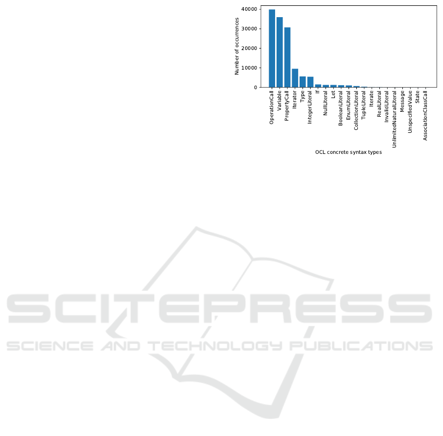
ple, EMMA has been used to investigate the usage of
the Object Constraint Language (OCL) (Warmer and
Kleppe, 2003) in practice, see Figure 3.
To perform all these analyses in a uniform way, the
count-analysis uses the Metrics functionality described
Figure 3: A histogram showing the number of occurrences
of OCL constructs in a large open-source dataset (Noten
et al., 2017).
in Section 4.2. As the data aggregation, described in
Section 4.4, stores its information at object granularity,
this functionality can be exploited to do counting. For
example:
•
We start by defining a metric “CountVertex” that
returns
1
for every Vertex in a Graph. Genera-
tion of such metrics can be fully automated as the
instantiation relations in EMF are standardized;
•
As data is stored on a per-object basis, a
CountVertex = 1 will be stored per object;
•
By counting (or summing) over all such values, we
reuse the generic metric-calculation framework to
do counting, obtaining figures such as the one in
Figure 3.
4.2 Metrics
As mentioned before, EMMA provides a generic
metric-calculation framework for EMF by exploiting
the standardization of instantiation relations. As an ex-
ample, to automatically generate the metrics described
in Section 4.1, one can look at a metamodel and create
a metric “CountX”, for every concept (
EClass
) X in
the metamodel. As no concepts other than those in the
metamodel(s), can be instantiated in the model, this
gives us a complete summary of the model.
Such standard metrics can answer a plethora of
questions, but are not sufficient for all cases. As such,
EMMA is designed to be extensible. For this, we allow
easy definition of custom metrics, as the examples in
Listing 1 (Mengerink et al., 2017b)) illustrate.
MOMA3N 2018 - Special Session on Model Management And Analytics
748
Listing 1: An example of metrics on a graph DSL.
@Metric ( name=" o u t d e g r e e " )
p u b l i c i n t out g o i n g ( V e r t e x v ) {
r e t u r n v . e dges ;
}
@Metric ( name=" numNodes " )
p u b l i c i n t out g o i n g ( Graph g ) {
r e t u r n g . nod es . s i z e ( ) ;
}
4.3 Differences
The second main type of analysis that EMMA sup-
ports is model differencing. Using EMFCompare
4
,
EMMA can systematically compute differences and
store them in a database. Aggregating such informa-
tion over various versions can give insight into evo-
lutionary behavior of the models in question. For
instance, model differencing is used to gain insight
into the most frequently occurring types of metamodel
evolution (Mengerink et al., 2016b), supporting the
challenges described in Section 2.3.
4.4 Data Aggregation
In previous work (Mengerink et al., 2017b), we have
already elaborated on the various aforementioned fea-
tures and analyses that EMMA supports. The core
strength of EMMA not explicitly showcased in that
work is the capability to freely aggregate data at vari-
ous levels:
•
Metrics are calculated and persisted on a per-object
basis;
• Membership of objects to files is recorded;
•
Membership of files to a particular collection
(“datasets” in EMMA terminology) is recorded;
The statistical analyses using the R (Ihaka and Gen-
tleman, 1996) integration within EMMA, or visualiza-
tions supported by EMMA (Mengerink et al., 2017b)
allow selection of data to be analyzed/visualized based
on the aforementioned aggregations. For example:
•
When analyzing a single file, one can perform
sanity checks such as “all attributes should have
non-null values”;
•
Combining measurements from multiple files, dis-
tributions may be observed. For example about
the the average complexity of OCL expressions in
open-source (Noten et al., 2017);
4
EMF Compare,https://www.eclipse.org/emf/compare/,
Accessed: 2017-11-01.
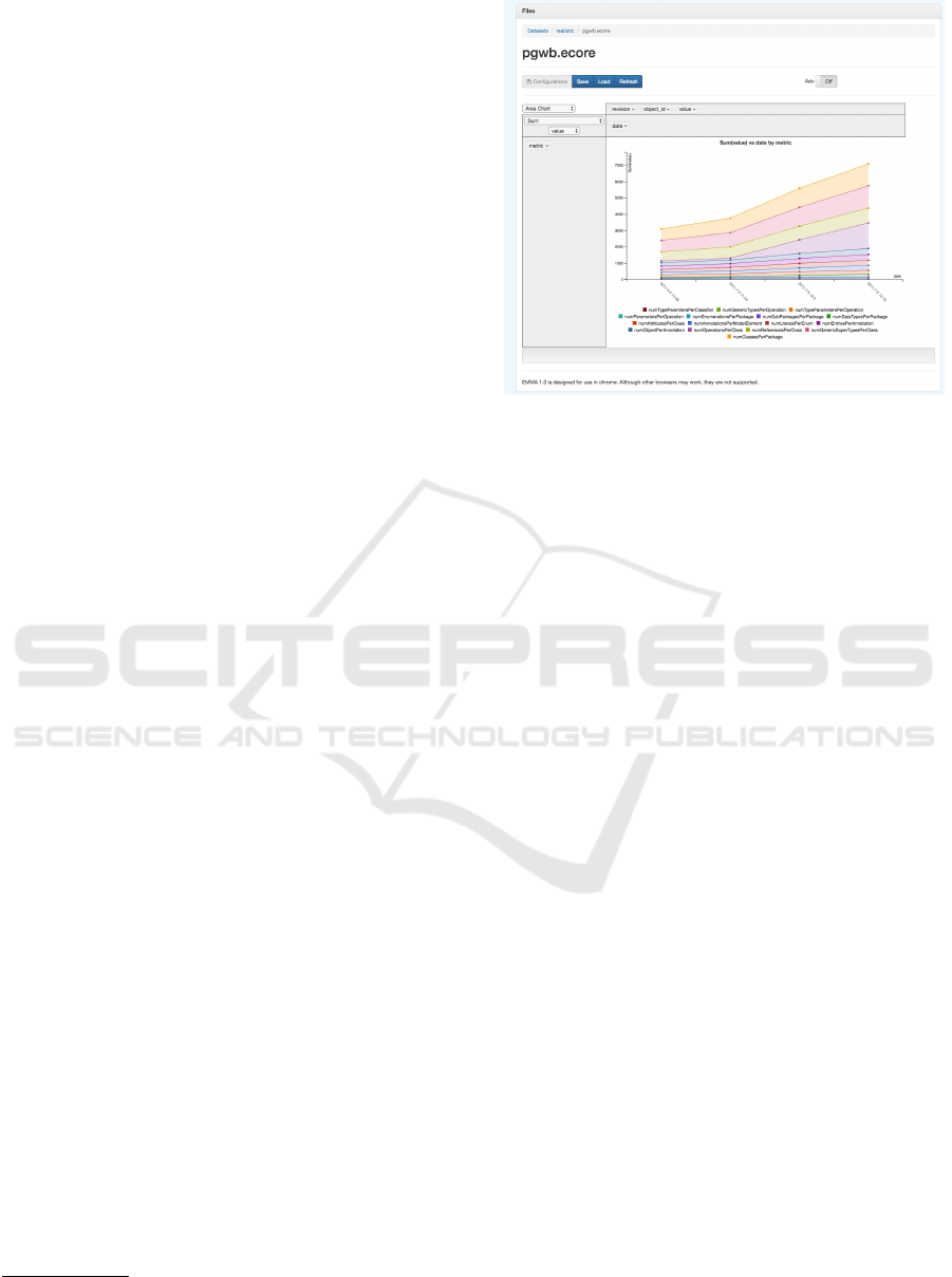
Figure 4: A screenshot of EMMA taken from (Mengerink
et al., 2017b), showing aggregation by date, which allows
analyses over time (e.g., evolution).
•
By taking dataset-level measurements, one can
also make better statements about individual files,
e.g., “this model is bad, because its complexity is
40% higher than the average model in the dataset”.
•
One can also compare measurements from two
datasets. For example to compare complexity of
open-source and industrial MDE artifacts (Men-
gerink et al., 2017a).
•
Orthogonally, aggregation by date is possible. This
allows analyzing artifacts over time. e.g., how
the size & structure of a DSL changes of time as
illustrated in Figure 4 (Mengerink et al., 2017b;
Vissers et al., 2016; Mengerink et al., 2016b).
These forms aggregation, coupled with the simple
but powerful out-of-the-box analyses, allows EMMA
to cater to a plethora of industrial analysis needs.
5 FUTURE RESEARCH
Multi-disciplinary System Engineering (MDSE)
ecosystems have proven to deliver effective design sup-
port resulting in improved system quality and reduced
development time. Although they provide a significant
step forward in industry, they only form a partial so-
lution. Still, quite a number of challenges have to be
addressed in order to deal properly with the increased
complexity of high tech systems development.
Conceptually.
To allow effective prediction and
trading-off of key system aspects concerning perfor-
mance, correctness, reliability and evolvability, a grand
Towards Automated Analysis of Model-Driven Artifacts in Industry
749

challenge concerns the identification and formalization
of the semantic relations between domain and aspect
models, spanning different levels of abstraction. En-
gineering principles, such as abstraction, architecture,
or decomposition, are different across disciplines. To
understand how these principles relate and impact each
other is another challenge to be addressed.
Modeling Effectiveness.
Empirical research is
needed to obtain convincing measurements of model-
ing effectiveness. What are the measurable benefits
of modeling? In industry, there is still a lot of discus-
sion about this. Regarding quality of models, one can
distinguish two directions:
•
Is the model a good abstraction of the system?
Does the model describe the modeled system suf-
ficiently accurate (‘just enough modeling’), such
that one can draw conclusions from it? What can
be and should be modeled, which is a trade-off
between expressivity and analytical tractability.
What is the (minimal) required expressivity to max-
imize its analytical tractability.
•
Is the model a good model? How to measure qual-
ity of the model themselves? Work on quality
models and attributes can be found for instance
on in (Gerpheide et al., 2016a; Gerpheide et al.,
2016b).
Tooling.
Currently, most mature tooling is text-
based, which makes it hard to reason and exploit the
structure of models. A lot of research has been done
to lift these tools to model/graph based tools and to
deal with scalability, see (Kolovos et al., 2013; Kehrer
et al., 2011; Maoz and Ringert, 2015). However, tools
that can be used at large scale in industry are still in
their infancy.
ACKNOWLEDGEMENTS
The authors thank Jeroen Voeten, Wilbert Alberts,
Sven Weber, Marc Hamilton and Rogier Wester for
stimulating discussions and constructive feedback on
earlier versions of this paper. Furthermore, we thank
the anonymous reviewers whose valuable comments
and suggestions helped to improve and clarify this
paper.
REFERENCES
Adyanthaya, S. (2016). Robust multiprocessor scheduling
of industrial-scale mechatronic control systems. PhD
thesis, Eindhoven: Technische Universiteit Eindhoven.
Alberts, W. (2016). ASML’s MDE Going Sirius.
https://www.slideshare.net/Obeo_corp/siriuscon2016-
asmls-mde-going-sirius. Accessed: 2017-11-01.
Babur, Ö. and Cleophas, L. (2017). Using n-grams for the
Automated Clustering of Structural Models, pages 510–
524. Springer International Publishing, Cham.
Babur, Ö., Cleophas, L., and van den Brand, M. (2016).
Hierarchical Clustering of Metamodels for Compara-
tive Analysis and Visualization, pages 3–18. Springer
International Publishing, Cham.
Di Rocco, J., Iovino, L., and Pierantonio, A. (2012). Bridg-
ing state-based differencing and co-evolution. In Mod-
els and Evolution, pages 15–20. ACM.
Diskin, Z., Kokaly, S., and Maibaum, T. (2013). Mapping-
Aware Megamodeling: Design Patterns and Laws. In
Software Language Engineering - 6th International
Conference, SLE 2013, Indianapolis, IN, USA, October
26-28, 2013. Proceedings, pages 322–343.
Favre, J.-M. (2005). Languages evolve too! changing the
software time scale. In Principles of Software Evolu-
tion, pages 33–42.
Fenton, N. and Bieman, J. (2014). Software metrics: a
rigorous and practical approach. CRC Press.
Fernández-Sáez, A. M., Genero, M., Chaudron, M. R.,
Caivano, D., and Ramos, I. (2015). Are forward de-
signed or reverse-engineered uml diagrams more help-
ful for code maintenance?: A family of experiments.
Information and Software Technology, 57(Supplement
C):644 – 663.
Gabmeyer, S., Kaufmann, P., Seidl, M., Gogolla, M., and
Kappel, G. A feature-based classification of formal
verification techniques for software models. Software
& Systems Modeling, pages 1–26.
García, J., Diaz, O., and Azanza, M. (2013). Model transfor-
mation co-evolution: A semi-automatic approach. In
SLE, volume 7745 of LNCS, pages 144–163. Springer.
Gerpheide, C. M., Schiffelers, R. R. H., and Serebrenik, A.
(2016a). Assessing and improving quality of QVTo
model transformations. Software Quality Journal,
24(3):797–834.
Gerpheide, C. M., Schiffelers, R. R. H., and Serebrenik, A.
(2016b). Assessing and improving quality of qvto
model transformations. Software Quality Journal,
24(3):797–834.
Hebig, R., Khelladi, D. E., and Bendraou, R. (2017). Ap-
proaches to co-evolution of metamodels and models:
A survey. IEEE Transactions on Software Engineering,
43(5):396–414.
Herrmannsdörfer, M. (2011). COPE - A workbench for the
coupled evolution of metamodels and models. In SLE,
volume 6563 of LNCS, pages 286–295. Springer.
Hutchinson, J. E., Whittle, J., Rouncefield, M., and Kristof-
fersen, S. (2011). Empirical assessment of MDE in
industry. In ICSE, pages 471–480.
MOMA3N 2018 - Special Session on Model Management And Analytics
750

Ihaka, R. and Gentleman, R. (1996). R: a language for data
analysis and graphics. Journal of computational and
graphical statistics, 5(3):299–314.
Iovino, L., Pierantonio, A., and Malavolta, I. (2012). On the
impact significance of metamodel evolution in MDE.
Journal of Object Technology, 11(3):3: 1–33.
Kehrer, T., Kelter, U., and Taentzer, G. (2011). A rule-
based approach to the semantic lifting of model differ-
ences in the context of model versioning. In 2011 26th
IEEE/ACM International Conference on Automated
Software Engineering (ASE 2011), pages 163–172.
Kolovos, D. S., Rose, L. M., Matragkas, N., Paige, R. F.,
Guerra, E., Cuadrado, J. S., De Lara, J., Ráth, I., Varró,
D., Tisi, M., and Cabot, J. (2013). A research roadmap
towards achieving scalability in model driven engineer-
ing. In Proceedings of the Workshop on Scalability
in Model Driven Engineering, BigMDE ’13, pages
2:1–2:10, New York, NY, USA. ACM.
Lambrechts, C. (2017). Metrics for control models in a
model-driven engineering environment. PDeng Thesis„
Technische Universiteit Eindhoven.
Leemans, M. and van der Aalst, W. M. P. (2015). Process
mining in software systems: Discovering real-life busi-
ness transactions and process models from distributed
systems. In 2015 ACM/IEEE 18th International Con-
ference on Model Driven Engineering Languages and
Systems (MODELS), pages 44–53.
Lehman, M. M. (1980). Programs, life cycles, and laws
of software evolution. Proceedings of the IEEE,
68(9):1060–1076.
Maoz, S. and Ringert, J. O. (2015). A framework for relating
syntactic and semantic model differences. Software &
Systems Modeling, pages 1–25.
Mengerink, J., Schiffelers, R. R., Serebrenik, A., and van den
Brand, M. (2016a). Dsl/model co-evolution in indus-
trial emf-based mdse ecosystems. In ME@ MODELS,
pages 2–7.
Mengerink, J., van der Sanden, B., Cappers, B., Serebrenik,
A., Schiffelers, R., and van den Brand, M. (2018).
Exploring dsl evolutionary patterns in practice: A study
of dsl evolution in a large-scale industrial dsl repository.
In Modelsward.
Mengerink, J. G. M., Noten, J., Schiffelers, R. R. H., van den
Brand, M. G. J., and Serebrenik, A. (2017a). A case
of industrial vs. open-source ocl: Not so different after
all. In 20th ACM/IEEE International Conference on
Model Driven Engineering Languages and Systems.
Mengerink, J. G. M., Serebrenik, A., Schiffelers, R. R. H.,
and van den Brand, M. G. J. (2016b). A complete
operator library for DSL evolution specification. In
ICSME 2016, Raleigh, NC, USA, pages 144–154.
Mengerink, J. G. M., Serebrenik, A., Schiffelers, R. R. H.,
and van den Brand, M. G. J. (2016c). Udapt: Edapt
extensions for industrial application. In IT.SLE, CEUR-
WS.
Mengerink, J. G. M., Serebrenik, A., Schiffelers, R. R. H.,
and van den Brand, M. G. J. (2017b). Automated
analyses of model-driven artifacts: Obtaining insights
into real-life application of MDE. In IWSM Mensura.
Noten, J., Mengerink, J. G. M., and Serebrenik, A. (2017).
A data set of OCL expressions on GitHub. In MSR.
Raffelt, H., Steffen, B., and Berg, T. (2005). Learnlib: A
library for automata learning and experimentation. In
Proceedings of the 10th international workshop on
Formal methods for industrial critical systems, pages
62–71. ACM.
Rose, L. M., Etien, A., Mendez, D., Kolovos, D. S., Po-
lack, F. A. C., and Paige, R. F. (2010a). Comparing
Model-Metamodel and Transformation-Metamodel Co-
evolution. In Model and Evolution Workshop.
Rose, L. M., Kolovos, D. S., Paige, R. F., and Polack,
F. A. (2010b). Model migration with Epsilon Flock.
In ICMT, volume 6142 of LNCS, pages 184–198.
Springer.
Rose, L. M., Paige, R. F., Kolovos, D. S., and Polack, F. A. C.
(2009). An analysis of approaches to model migration.
In MoDSE-MCCM, pages 6–15.
Schiffelers, R. (2017). Model Driven Development
of TWINSCAN software, but not from scratch!
http://www.ictopen.nl/content/Speakers/invited+
speakers+per+track. Accessed: 2017-11-01.
Schiffelers, R. R. H., Alberts, W., and Voeten, J. P. M. (2012).
Model-based specification, analysis and synthesis of
servo controllers for lithoscanners. In Proceedings
of the 6th International Workshop on Multi-Paradigm
Modeling, MPM ’12, pages 55–60, New York, NY,
USA. ACM.
Thüm, T., Apel, S., Kästner, C., Schaefer, I., and Saake,
G. (2014). A classification and survey of analysis
strategies for software product lines. ACM Comput.
Surv., 47(1):6:1–6:45.
van Beek, D. A., Fokkink, W. J., Hendriks, D., Hofkamp, A.,
Markovski, J., van de Mortel-Fronczak, J. M., and Re-
niers, M. A. (2014). CIF 3: Model-Based Engineering
of Supervisory Controllers, pages 575–580. Springer
Berlin Heidelberg, Berlin, Heidelberg.
van der Sanden, B., Reniers, M., Geilen, M., Basten, T., Ja-
cobs, J., Voeten, J., and Schiffelers, R. (2015). Modular
model-based supervisory controller design for wafer
logistics in lithography machines. In 2015 ACM/IEEE
18th International Conference on Model Driven En-
gineering Languages and Systems (MODELS), pages
416–425.
Vissers, Y., Mengerink, J. G. M., Schiffelers, R. R. H., Sere-
brenik, A., and Reniers, M. A. (2016). Maintenance of
specification models in industry using edapt. In FDL,
pages 1–6.
Warmer, J. and Kleppe, A. (2003). The Object Constraint
Language: Getting Your Models Ready for MDA.
Addison-Wesley, 2 edition.
Whittle, J., Hutchinson, J., and Rouncefield, M. (2014). The
state of practice in model-driven engineering. IEEE
software, 31(3):79–85.
Towards Automated Analysis of Model-Driven Artifacts in Industry
751
