
Fast Simulation Preorder Algorithm
Evgeny Kusmenko, Igor Shumeiko, Bernhard Rumpe and Michael von Wenckstern
Software Engineering, RWTH Aachen, Germany
Keywords:
Behavioral Compatibility, Component & Connector Model, Simulink, Evaluation on Automotive Models,
Model-Checking.
Abstract:
Automotive industry uses model checking approaches to ensure behavioral backward compatibility of different
variants and versions of software components to enable higher re-usability. Due to the lack of scalability, our
already presented backward model-checking approach only allowed compatibility checks for small and mid-
size components. Therefore, this paper presents several optimizations, such as normalizing and hashing the
Expression Abstract Syntax Tree for faster evaluations and the creation of mappings for internal Simulink
variables to avoid the need to unfold them. These optimizations lead to a tremendous decrease in execution
time of our backward-compatibility checks between MATLAB Simulink components enabling the support of
larger models. Besides describing the methodology behind the new fast simulation preorder algorithm, this
paper also evaluates the different steps of the new algorithms for a driver assistant system provided by Daimler
AG.
1 INTRODUCTION
Nowadays, embedded software controls the func-
tional cycle of almost every device. Exploitation of
such devices as cars is often bound with a risk for
health and life of human beings. For that reason em-
bedded software, used in automotive industry must be
highly reliable. This means that significant amount
of time and budget is dedicated by programmers to
test and develop new software. Frequently, multi-
ple versions of a software component or an extension
of old software to use in a new context are required.
This gives rise to the question, whether the new ver-
sion can be used instead of the old one. In other
words, if the components are backward compatible.
To be backward-compatible, it must be checked if the
new component contains the functionality of the old
one. In this case, manual analysis is very error prone
and time consuming and it is preferred to perform
automated checks. In (Rumpe et al., 2015), Mon-
tiMatcher, a model-checking algorithm to automati-
cally test Simulink components for behavioral equiv-
alence was proposed. It is based on the idea of trans-
forming Simulink components under consideration to
input/output transition systems (I/O-TS) (Zhou and
Kumar, 2012) and then to check whether all the ex-
ecution paths of the second component are a super-
set of the execution paths of the first one. Thereby, a
model checking tool, namely Microsoft’s Z3 Solver,
is used (Miller et al., 2010) to check whether guard
conditions and/or output assignments are similar (you
can ask Z3 is ∀a, b, c ∈ [0, 250] : c · a + a · b == a ·
(b + c) and Z3 will answer sat (yes), unsat (no) or
timeout (unknown)). It turned out that in some cases
the execution of MontiMatcher can take more time
than checking components for behavioral compatibil-
ity manually. For this reason this article presents a
few optimization attempts aiming to reduce the time
necessary to find out whether components are com-
patible.
The rest of the article content is given as follows:
Section 3 provides more concrete information on the
performed optimizations, Sections 4, 5, 6 describe
disjunctive normal form, index tree, global variables
optimizations respectively as well as a feasibility as-
sessment of using the automated theorem prover Is-
abelle for behavioral compatibility checking (Paul-
son, 1994). Sections 7, 8, and 9 provide an evaluation,
an overview of related works and a final conclusion.
2 FOUNDATIONS
Simulink (Mathworks Inc., 2016) is a component &
connector based language very popular for model
based software development in engineering disci-
plines, particularly in the automotive industry. In
Simulink a component represents a piece of logical
functionality. Input and output ports define the in-
256
Kusmenko, E., Shumeiko, I., Rumpe, B. and Wenckstern, M.
Fast Simulation Preorder Algorithm.
DOI: 10.5220/0006722102560267
In Proceedings of the 6th International Conference on Model-Driven Engineering and Software Development (MODELSWARD 2018), pages 256-267
ISBN: 978-989-758-283-7
Copyright © 2018 by SCITEPRESS – Science and Technology Publications, Lda. All rights reserved

terface of such a component. Data flows between
components is defined by connectors between out-
put ports (providing some data) and input ports (us-
ing this data). The behavior of a component may be
provided either by MATLAB code or by a hierarchi-
cal decomposition into subcomponents. Furthermore,
Simulink offers a large library of predefined compo-
nents for multiple domains including control, signal
processing, computer vision, and others.
This paper presents several optimizations for the
model checking algorithm introduced by (Rumpe
et al., 2015). The activity diagram for checking func-
tional compatibility of two Simulink components is
shown in Figure 1. If the components are compati-
ble they can be replaced by each other in the system.
Hence, it can be guaranteed that if one component is
replaced by its newer version, the whole system con-
tinues functioning as expected, i.e., as with the old
version of this component. It means that for all inputs
that are accepted by the old version, the new version
generates the same outputs. However, for inputs pre-
viously not accepted by the system, the new version
may exhibit new behavior.
As the first step, the input Simulink models are
transformed to a control flow graph. With its help all
the output dependencies and update functions of in-
ternal variables are discovered. The next step is clone
detection which is done on the basis of control flow
analysis. It neutralizes all the parts of the component
that do not have any influence neither on output cal-
culation nor on internal variable updates. Such ele-
ments do not take part in the further analysis which
simplifies the complexity. Then control flow graphs
are transformed to Input/Output Extended Finite Au-
tomata (I/O-EFAs (Zhou and Kumar, 2012)) based
on output ports. Thereafter, a state space calculation
is performed which is basically a transformation of
I/O-EFA to I/TO-TS where state names are combined
with all possible values of internal variable update
functions. This transformation often results in a state
space explosion (Baier et al., 2008). As the next step
the program locks all free ports allowing to take into
account that new functionality of a component can be
introduced by increasing the number of its input ports.
The old and the new version can still be compatible if
extra ports added to the new version are locked with
some static values and so the new version exhibits the
behavior of the old one. In the next step, a simulation
is in fact running the algorithm described in detail by
(Rumpe et al., 2015). The algorithm checks whether
both I/O-TSs are in simulation preorder relation.
The next section states which problems in the pro-
gram workflow we are tackling in this article and how
we can solve them.
ValidationTool
Simulink
model (mdl)
Simulink-
Compile-
Logfile
Create
control flow
graph
MatlabControl
«uses»
Trans-
formation to
I/O-EFA
Microsoft
Z3-Solver
«uses»
State Space
calculation
CUDA
domain calculation
«uses»
Locking free
ports
Compatibility
statement
MontiArc-
Automaton
AD
Clone detection
via control flow
analysis
«uses»
Divide I/O-EFA
based on
output ports
Simulation
Figure 1: Program workflow to check compatibility of
Simulink components (Rumpe et al., 2015).
3 MOTIVATION
As mentioned earlier, Simulink components are trans-
formed to I/O-TS in order to perform behavioral com-
patibility analysis. The resulting I/O-TSs contain sets
of states and transitions that represent execution paths
of modeled software. The algorithm (presented in
(Rumpe et al., 2015)) checks whether there is a sim-
ulation preorder relation between two I/O-TSs. Since
the complexity of TSs is very high even for relatively
simple components i.e they contain big number of
states and transitions, checking for simulation pre-
order relation causes many SMT calls. These calls are
needed to determine which outgoing transitions from
a state of the second TS are activated if one transition
from the current state of the first TS becomes active.
To reduce SMT calls and consequently the execution
time, the disjunction normal form (DNF) and index
tree optimizations are introduced.
The DNF optimization organizes transitions
guards such that semantically equal but syntactically
possibly different guards obtain the same syntactical
appearances. As a result repeated expressions that
are joined via conjunction in guard conditions can be
omitted making SMT calls more efficient. Further-
more, guard conditions can be compared syntactically
avoiding SMT-calls and decreasing execution time. It
is expected that this optimization will accelerate the
checking procedure during the simulation step (see
Figure 1) at the expense of reduction of SMT calls
to check whether transitions of states of two I/Os are
simulated by each other (or just in one direction).
To accelerate the selection process of implied tran-
sitions of an I/O-TS state, the index tree optimization
was proposed. The idea is to build an index tree for
each I/O-TS state of the first automaton to map guard
variables to corresponding transitions. Then the index
Fast Simulation Preorder Algorithm
257

Guard
Guard Normal
Form(GNF)
Disjunctive
Guard (DNF)
Hashed-Guard
(HDNF)
Optimized
HGDNF
1 2 3
4
Figure 2: Steps needed to transform a Guard expression to
optimized Hash-Guard-DNF expression.
tree is queried with the guard variables of the second
automaton to find all transitions of the first automa-
ton implying the guard of the second automaton. One
gets all transitions that can be potentially activated if
the query transition becomes active. Consequently,
an SMT solver does not have to check transitions that
cannot be activated a priori. This leads to a higher ef-
ficiency of execution. This optimization is developed
to reduce number of SMT calls even further and not
to issue them for cases where it can be seen that the
formulas to be checked (made of guard expressions)
are a priori not satisfiable.
While two previously mentioned optimizations
consider a possibility of acceleration of the transition
filtering process when components are already trans-
formed to I/O-TSs, the global variable optimization
is intended to avoid transforming components to I/O-
TSs (see Figure 1), since it leads to the state space
explosion problem (Baier et al., 2008) even for sim-
ple components. The proposed optimization tries to
find to correspondence between global variables of
both components. If the matching is successful be-
havior compatibility check can be performed without
unfolding of global variables. It means that in Fig-
ure 1 the step for transformation to I/O-TS is skipped
and compatibility statement is directly derived with-
out the simulation step.
The last optimization tries to formalize and solve
the task of behavioral compatibility analysis in a
generic theorem prover Isabelle. Performance gained
is yet to be assessed. This article will discuss state
of the research and show problems currently being
faced.
4 DISJUNCTIVE NORMAL FORM
OPTIMIZATION
The main purpose of the applied optimization is to
normalize guard expressions to make syntactical and
semantical comparisons equivalent. If such equiv-
alence is reached, it allows to make statements on
whether one guard expression is the same seman-
tically without issuing an SMT-call. Reducing the
number of SMT-calls in simulation preorder work-
flow makes the procedure consume less system re-
sources and terminate in a shorter time.
The optimization sequence integrated in the
Simulation-tool MontiMatcher is shown in Figure 2.
The following sub-chapters explain each step of the
Disjunctive Normal Form (DNF) transformation and
provide examples for better understanding.
4.1 1st Step: Guard to Guard Normal
Form (GNF) Transformation
At this step all the guard expressions are transformed
into guard normal form. It is performed by equivalent
transformation of guards to exclude the logical oper-
ators <, >, ≤ as well as the infix operator −. If pos-
sible distributive law of multiplication is applied and
sums like 2 · b are decomposed to summands: b + b.
The right part of guards must contain zero. Let us take
for example the following guard expression:
d
∧ (a ≤ 10 ∨ a ≤ 10 ∨ (b > 0 ∧ b > a) ∨ ¬d) (1)
∨ (3 + a) · (c + 2 · b) ≥ b (2)
Applying negation rule of boolean algebra, distribu-
tive law of multiplication and basic rules for inequal-
ity simplification we get:
d ∧ (10 + (−a) ≥ 0 ∨ 10 + (−a) ≥ 0 (3)
∨ (¬(−b ≥ 0) ∧ ¬(−b + a ≥ 0)) ∨ ¬d) (4)
∨ (b + b + b + b + b + a · c + c + c + c (5)
+a · b + a · b ≥ 0) (6)
After this step, algebraic expressions used in transi-
tion guards are normalized, e.g. they look the same
syntactically if they have the same meaning. For ex-
ample the expressions b + a + a and b + 2 · a result
in a + a + b, which enables syntactical comparison to
check whether these are identical expressions.
The result of this step is the input for the 2nd trans-
formation.
4.2 2nd Step: Guard-NF to Guard
Disjunctive Normal Form (GDNF)
Transformation
As it can be seen from the previous example, the re-
sulting expression for the guard still contains con-
junction operations. Applying the distributive law of
boolean algebra to the last equations of the previous
subsection we get an expression representing disjunc-
tion of conjunctive clauses:
d ∧ 10 + (−a) ≥ 0
∨
d ∧ 10 + (−a) ≥ 0
∨
d ∧ ¬(−b + a ≥ 0) ∧ ¬((−b) ≥ 0)
∨
d ∧ ¬d
∨
(b + b + b + b + b + a · c + c + c + c + a · b + a · b ≥ 0)
(7)
Having all the guard expressions in DNF allows to
make statements whether one guard enables another
MODELSWARD 2018 - 6th International Conference on Model-Driven Engineering and Software Development
258

&&
a
b
c d
&&
a b
c d
&&
a
b
c
d
&&
&&
&&
&&
a)
b) c)
Figure 3: Prefix ASTs representation.
one. For example, if both guard expressions have
one or more equal conjunctive clauses it immediately
means that they both evaluate to true or false if their
variables them take the same value. Also if one of the
guard conjunctors is known to be false or true it can
be immediately concluded that the whole expression
becomes false or true respectively. This accelerates
the processes of making decision on satisfiability by
the SMT solver.
The concatenation of guard conditions of the tran-
sitions of the two automata during the simulation pro-
cess leads to many invalid guard expressions (such as
a ∧ ¬a). The GDNF step detects these invalid condi-
tions, and therefore, these conditions will not be pro-
cessed later anymore.
4.3 3rd Step: Guard-DNF to
Hash-Guard Disjunctive Normal
Form (HGDNF) Transformation
At this step new hash ASTs (Abstract Syntax Trees)
were introduced to store and perform operations on
GDNF expressions. One of the operations allowing
to speed up comparison of two ASTs is the ability of
such objects to produce hash values that correspond
to their inner structure. Hash values are used to make
it possible to sort summands in guards, e.g that the
expressions b + v + 2 · a + c and v + c + a + b + a have
the form a + a + b + c + v after the transformation.
To normalize ASTs, the prefix notation (as shown
in Figure 3 (c)) is used to join the same operation
nodes wherever possible into a single operation node.
Therefore, conjunctions like (a ∧ (b ∧ (c ∧ b)))) are
normalized and can be compared syntactically. This
was not possible before since two structurally differ-
ent AST expressions would produce different hash
values, even though they are the same semantically
like in Figure 3. Applying Prefix-ASTs reduces also
the time needed for traversing the nodes of the tree
; when traversing the infix tree in Figure 3 a) and b)
the algorithm needs to visit 7 nodes while in c) it only
needs 5 nodes. The expression shown in Equation 7
can be represented as an AST in prefix form:
∨(≥ (+ (b, b, b, b, b, b, c, c, c, ·(a, b), · (a, b), · (a, c)), 0)
∧ (≥ (+(−b, a) , 0), (d), ¬(≥ (−b, 0)))
∧ (¬ (d), (d))
∧ (≥ (+(−a, 10) , 0), (d))
∧ (≥ (+(−a, 10) , 0), (d)))
(8)
Figure 4 shows a part of the AST hash tree for the
example. Pay attention that all the nodes are sorted in
accordance with the hash order.
4.4 4th Step: HGDNF to Optimized
HGDNF Transformation
To further simplify the AST expressions we can make
use of Hash ASTs to detect situations in which the
guard conditions can by directly evaluated to true of
false.
#(∨a, b) = #
java
(∨ a b) = #(∨b, a) (9)
#(< a, b) = −(#(≥ a, b)) (10)
To achieve this, the ASTs participating in the
guard condition must be compared with each other.
In case of equal hash values an additional comparison
of ASTs must be performed, since a hash function is
non-surjective, and therefore applying it to different
arguments can lead to the same result. If the AST
check shows a positive result, it can be concluded
after the SMT check (due to non-surjectivity of the
used hash function) that both ASTs are equal. But
in cases where the hash values of ASTs under com-
parison are non-equal the AST check can be skipped
and the procedure demonstrates higher performance
since the AST check takes considerably more time
than the comparison of two integer values. Thus,
since #(¬(d)) = −#((d)) the respective disjunction
can be evaluated to false and excluded after the AST
check. As a result we get:
∨( ∧ (≥ (+ (−b, a), 0), (d), ¬(≥ (−b, 0)))
≥ (+ (b, b, b, b, b, b, c, c, c, ·(a, b) , ·(a, b) , ·(a, c)) , 0)
∧ (≥ (+(−a, 10), 0), (d))
∧ (≥ (+(−a, 10), 0), (d)))
(11)
Fast Simulation Preorder Algorithm
259

…
…
OR
AND
d
≥0
+
10neg
a
NOT
≥0
+
a
neg
b
AND
dneg
d
100
-1624984859
-1251917487
1251917487
98
97
-98
-202777987
1634047730
97
-97
-100
100
100
878251454
647274798
1567
…
#(“a”)
-1∙97
#(“+; -97; 1567”)
#(“>=0; -1624984859”)
~(-1251917487)
#(“AND;100; 1251917487; 1634047730”)
#(“…”)=“…”.hashCode()
#(“OR;…; 647274798; 878251454;...”)
Figure 4: Part of the AST tree for Equation 8.
After this transformation step it becomes possible
to extract port variables from the guard expressions.
A set of guard variables is used in the next section
in order to build the index tree for transition filtering
optimization.
5 INDEX TREE OPTIMIZATION
FOR TRANSITION FILTERING
One step in the automata simulation preorder relation
algorithm (Rumpe et al., 2015) checks which transi-
tions of the second I/O-TS can potentially be activated
by a given transition of the first I/O-TS. This opti-
mization excludes transitions from the set of poten-
tially activated transitions; the smaller set size results
in less expensive Z3 calls to filter the actually acti-
vated transitions from the potential ones. For exam-
ple in Figure 5 to understand whether the transition C
in Figure 5a is simulated by the transitions of A S(i)
in Figure 5b, each set of port variables of the guard
expression in GDNF form (i.e. {a, b} and {c}) of
transition C must be checked for being a super set for
sets of conjunction variables for transitions of A S(i).
5.1 Earlier Approach
Using AST expressions allows to extract all the ports’
variables used on a given transition. The algorithm
checks whether the variable set of the AST guard
expression of the given transition (tr1) is a superset
of variables of a selected transition taken from the
other automaton. If it is the case, the first transition
(tr1) potentially activates the one (tr2) from the other
automaton. To exclude wrong implications such as
¬a ⇒ a where the left guard is superset of the right
guard, a SMT call checks the complete implication.
More formally: A1 and A2 are variable-sets con-
taining all used variables in Guard1 and Guard2.
Guards are defined as conjunction of expressions
with only one non-trivial input variable (term
v
, v ∈
Inputvariables, Interpretation(Dom(v)) 2 term
v
):
Guard1, Guard2 ∈
V
i
term
v
. Then, the following
holds: (A1 * A2) =⇒ (Guard2 ; Guard1) =⇒
(Guard1 Guard2). From A1 * A2 we know that
A1 contains at least one element that is not in A2. Ex-
ample: a ∧ b ; a ∧ c, since {a, b} + {a, c}.
After port variable extraction, the Java and Guava
collection frameworks check the superset relation be-
tween variable sets. For that for transition of A
S(i)
the procedure must go through all the port variables
sets for transitions of B S(i). Obviously it is not very
efficient since all the transitions of B S(i) are checked
numerous times and in general during the simulation
process states of I/O-TSs can be visited several times,
and for each time the filtering procedure must be exe-
cuted with the same overhead.
5.2 Index Tree Approach
The bottle neck of the described approach is that the
algorithm must iterate through all the transitions of
A S(i) for each transition of B S(i). Thus, in our
example all the A S(i) transitions must be traversed
three times. Taking into consideration that during the
simulation check states of I/O-TSs can be visited sev-
eral times and, therefore, this procedure may be re-
peated, this can create an overhead in terms that the
same operations are executed numerous times.
MODELSWARD 2018 - 6th International Conference on Model-Driven Engineering and Software Development
260

B_S(i)
{{a,b,c}}
{{b,c}}
{{a,b},{c}}
A_S(i)
{{a,b},{b}}
{{a,c}}
{{a},{b}}
{{c}}
{{a,b,c},{b,c}}
(1)
(5)
(4)
(3)
(2)
(A)
(B)
(C)
Root(A_S(i)):∅
0
a:{3}
4
b:{3,5}
2
c:{4}
1
b: {3,5}
6
c:{2,3,4}
5
c:{1,3,4,5}
7
c:{1,3,5,4}
3
a) b) c)
Figure 5: To help answer the question whether state B S(i) (b) simulates state A S(i) (a), the index tree (c) was built.
As an attempt to make this procedure faster an in-
dex tree (as shown in Figure 5 c) is created. Its size
depends on the number of port variables participating
in transitions of A S(i). The conjunction subsets of
B S(i) serve as queries for the tree. Numbers of the
activated transitions of A S(i) are obtained as an an-
swer. Such implementation is possible since all the
variables of the conjunctions are sorted and if further
traversing of the tree becomes not possible, it states
that the answer to the query can already be read. Cur-
rent implementation uses a pre-calculated structure to
reference nodes that contain transitions activated by
the current traversing path.
For example if the node number 6 ({a, b}) has
been reached it means that the query activates all the
transitions referenced as index for nodes 2 (a only) , 4
(b only), and 6 (a and b). The variables a, b, and c are
only place holders; and since the variables are ordered
they can be mapped to them directly and the prede-
fined structure with their dependency links (as in the
example 6 → {2, 4, 6}) can be used. It allows to tra-
verse all the transitions of A S(i) only once. This tra-
verse happens during creation of the index tree. After
the index tree is built transition filtering is done just
by querying the tree, which is estimated to be faster
then going though all the transitions each time. The
procedure only has to create the index tree once which
allows to save time if the I/O-TS states are revisited.
6 GLOBAL VARIABLE
OPTIMIZATIONS
6.1 Strategy to Avoid Internal Variable
Unfolding by using Z3
Now we demonstrate a strategy for the minimization
of global variable unfolding. It is possible if depen-
dencies between internal variables can be found.
Since Microsoft’s Z3 solver cannot find arbitrary
dependencies (complex mapping functions from
one variable to another one) automatically, this
algorithm focuses on linear dependencies between
two variables as it can ask the Z3 solver to calculate
(if they exist) the coefficients (factor and offset) for
the linear mapping from one variable to another. In
case, the automata contain non-linear parts in the
output statement and/or update functions, it may be
possible to find linear relationship between some
variables. The remaining ones must be unfolded to a
I/O-TS.
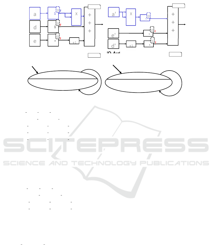
Two components shown in Figure 6 are taken
as an example. They have different structures but
execution yields the same output for both automata
if the input is equal. Buffers (denoted as Z
−1
)
define global variables. The values calculated in the
previous time step are used for the computation. The
initial values of the internal variables are indicated
as input to the I/O-automata, that are the models of
the shown components. Input ports are denoted as
a, d, e for the first automaton and as a
0
, e
0
, d
0
for the
second one. Operations performed on numbers are
summation and multiplication.
As the first step all the linear relationships are
discovered by requesting SMT solver to check the
internal variables on linear dependency. An example
of such a check is shown in Equation 12. The
equation expresses that there is a correspondence
between global variables of two components. If
this is the case for some variables SMT solver
defines at this step which equations can be solved
against coefficients x. Apparently the expression
(x11Prev a + x12Prev d + x13Prev e + x10) = a · a
cannot be resolved since it contains non-linear opera-
tion a · a. As the result of this step this expression is
discarded as well as coefficients x11, x12, x13, x10. It
means that there is non-linear relation between any
of the global variables of the first I/O-automaton and
the variable Prev a
0
of the second automaton.
Fast Simulation Preorder Algorithm
261
a
d
z
-1
+
+
+
Prev_a
Component 1:
z
-1
a'
+
1
+
+
+
Component 2:
0
Prev_a = 0
Prev_d = 0
Prev_e = 0
[true]
I/O-Automaton 1:
[true]
I/O-Automaton 2:
y =
Prev_a*Prev_a + Prev_d + Prev_e+1
Prev_a = a
Prev_d = d
Prev_e = e
SL
SL
I/O-EFA
I/O-EFA
e
z
-1
e'
d'
z
-1
z
-1
X
Prev_d
Prev_e
a
d
e
y
0
0
y'
e'
d'
a'
Prev_e'
Prev_d'
0
1
d'+1
Prev_a' = 0
Prev_e' = 0
Prev_d' = 1
+
1
z
-1
0
X
Prev_a'
y‘ = Prev_a‘ + Prev_e‘ + Prev_d‘
Prev_a‘ = a‘*a‘
Prev_e' = e‘
Prev_d‘ = d‘+1
Figure 6: Components and their respective automatons for comparison.
∀d, e,Prev a, Prev d, Prev e
(Prev
a
= a ∧ Prev d = d ∧ Prev e = e
∧ (x11Prev a + x12Prev d + x13Prev e + x10) = a · a
∧ (x21Prev a + x22Prev d + x23Prev e + x20) = e
∧ (x31Prev a + x32Prev d + x33Prev e + x30) =
d + 1)
(12)
After removing the non-linear part of the system
in Equation 12, it becomes Equation 13. Invoking
the SMT solver on Equation 13 finds all linear co-
efficients (x20 = 1, x21 = 0, x22 = 1, x23 = 0, x30 =
0, x31 = 0, x32 = 0) to express relationship between
the variables of the automaton.
∀d, e, Prev a, Prev d, Prev e
(Prev
a
= a ∧ Prev d = d ∧ Prev e = e
∧ (x21Prev a + x22Prev d + x23Prev e + x20) = e
∧ (x31Prev a + x32Prev d + x33Prev e + x30) =
d + 1)
(13)
Finally the expressions for the output functions
are formulated considering calculated coefficients.
Both automata are unfolded into the both I/O-TSs
shown in Figure 7, whereby only the remaining vari-
ables Prev a and Prev a´ are unfolded. This signif-
icantly reduces the number of states in the I/O-TSs.
If the linear correspondence between the variables of
both automata were not detected, all three global vari-
ables would need to be unfolded and this would result
in an I/O-TS with 27 states and 729 transitions for
both automata. Comparing these two automata with
three unfolded variables would lead to 19 683 SMT
calls in the simulation phase only to check whether
transitions of the first automaton implies transitions
of the second one. In contrast to that, the new ap-
proach (which removes all linear-dependent variables
between both automata) needs only 27 SMT calls. Al-
ready on this simple example we gain a speed-up fac-
tor of over 700 for the simulation step. Applying the
simulation algorithm of the automata in Figure 7 re-
veals that both systems produce the same output for
the same input.
Due to the control-based behavior (e.g PID con-
trollers) of cyber-physical systems many previously
calculated values (e.g. for calculating differences
as approximations of derivatives) need to be stored.
Most likely, if two systems have the same behav-
ior, both systems also store the same previously cal-
culated values; but since Simulink derives internal
names for atomic blocks based on the graphical lay-
out of the system, the names of the blocks that store
the same values may be different. This approach was
created to address this issue.
6.2 Strategy to Avoid Internal Variable
Unfolding by using Isabelle
An alternative direction of research is to check be-
havioral compatibility using an automated theorem
prover. Figure 8 demonstrates how compatibility of
the components in the example can be checked with
the Isabelle theorem prover (Paulson, 1994). The up-
date functions are defined with definitions and then
both outputs are shown to be equal. However for more
complex components this approach has some prob-
lems with automatization of the compatibility check,
since update functions are often recursive and equal-
ity of output functions must be proved by induction.
MODELSWARD 2018 - 6th International Conference on Model-Driven Engineering and Software Development
262

y = Prev_a*Prev_a + Prev_d + Prev_e+1
Prev_a= a
a={0,1,2}
0
y = Prev_d
+ Prev_e+1
a=0
1
y = Prev_d
+ Prev_e+2
2
y = Prev_d
+ Prev_e+5
a=2
a=0
a=0
a=1
a=1
a=2
a=0
a=1
a=2
y' =
Prev_a' + Prev_e+ Prev_d+1
Prev_a ' = a*a
a={0,1,2}
0
y ' = Prev_d
+ Prev_e+1
a=0
1
y ' = Prev_d
+ Prev_e+2
4
y ' = Prev_d
+ Prev_e+5
a=2
a=0
a=0
a=1
a=1
a=2
a=0
a=1
a=2
Figure 7: The I/O-TSs for the components in the example. It can be seen that both I/O-TSs have the same execution sequences.
definition Prev_a :: "nat⇒(nat⇒nat) ⇒ nat" where
"Prev_a t a=(if t=0 then 0 else a (t-1))"
definition Prev_aprime :: "nat⇒(nat⇒nat) ⇒ nat" where
"Prev_aprime t a=(if t=0 then 0 else (a (t-1))*(a (t-1)))"
definition Prev_d :: "nat⇒(nat⇒nat) ⇒ nat" where
"Prev_d t d=(if t=0 then 0 else (d (t-1)))"
definition Prev_dprime :: "nat⇒(nat⇒nat) ⇒ nat" where
"Prev_dprime t d=(if t=0 then 1 else (d (t-1))+1)"
definition Prev_e :: "nat⇒(nat⇒nat) ⇒ nat" where
"Prev_e t e=(if t=0 then 0 else e (t-1))"
definition Prev_eprime :: "nat⇒(nat⇒nat) ⇒ nat" where
"Prev_eprime t e=(if t=0 then 0 else e (t-1))"
lemma presentation_example :
"Prev_a t a*Prev_a t a+Prev_d t d+Prev_e t e+1=
Prev_aprime t a+Prev_eprime t e+Prev_dprime t d"
using Prev_a_def Prev_aprime_def
Prev_d_def Prev_dprime_def Prev_e_def Prev_eprime_def
by auto
Isabelle
Figure 8: Isabelle proof to show that components are equal.
Induction proves frequently require defining several
supplementary lemmas that describe dependency be-
tween global variables update functions. Finding de-
pendencies of such relations is hard to automatize.
7 EVALUATION
The optimized MontiMatcher framework using the
here presented fast simulation preorder algorithm has
been tested against the Advanced Driver Assistent
System (ADAS) provided by Daimler AG. In a pre-
viously case study (Bertram et al., 2017) on structural
requirement verification we made all Simulink mod-
els via web-export available under: http://www.se-
rwth.de/materials/cncviewscasestudy/.
definition prev_a :: "nat⇒(nat⇒bool)⇒ bool" where
"prev_a t a=a t"
definition out1 ::"nat⇒(nat⇒bool)⇒bool" where
"out1 t a =(if(prev_a t a ∧ a t) then True else
if(¬prev_a t a∧a t) then False else
if(prev_a t a∧¬a t) then False else True )"
definition prev_a2 :: "nat⇒(nat⇒bool)⇒ bool" where
"prev_a2 t a=a t"
definition out2 ::"nat⇒(nat⇒bool)⇒(nat⇒bool)⇒bool"
where "out2 t a c =(if(prev_a2 t a ∧ a t ∧ c t) then
True else if(¬prev_a2 t a∧a t ∧ c t) then False else
if(prev_a2 t a∧¬a t ∧ c t) then False else
if (¬c t) then True else True )"
lemma portFixation :"∃a2. out1 t b1 = out2 t a1 a2"
using out1_def out2_def prev_a_def prev_a2_def by auto
Isabelle
Figure 9: Port fixing Isabelle prove. The left right hand
part contains b1(t) function instead of a1(t). Despite that
the output functions are proved to be equal
In the rest of this evaluation section we use the
following abbreviations:
CC4 CruiseControl component of version 4
CC3 CruiseControl component of version 3
FLS FAS Limiter component with sign detection
FLN FAS Limiter component without sign detection
act active output port of FLS or FLN
kmh kmh (speed) output port of FLS or FLN
lim LimiterSetVariable in Simulink subsystem of
FLS or FLN, this is reduced to an output port as
all components of the ADAS only need the current
value and no history.
Performance improvements gained via the DNF
optimization are given in Table 2. In cases when both
tested components are almost equal the optimization
Fast Simulation Preorder Algorithm
263
leads to up to 47 % acceleration for the overall pro-
cess. For non-compatible components or simulation
directions the optimized procedure shows some loss
of performance, since in this case more information
needs to be disproved. Besides that, processes to build
supplementary constructions inside the automata ob-
jects also take computation resources. Such processes
include transforming all nodes into AST hash-nodes,
computing DNF expressions, concatenating, etc. It is
also important to notice that if the automata are reused
in later simulation checks, the performance gain will
be greater, since all the necessary supplementary con-
structions are built on the previous steps.
The simulation results of the global variable opti-
mization are shown in Table 1. It can be seen that in
comparison to the DNF results the algorithm demon-
strates acceleration up to ten times (FLS lim ← FLN
lim). Also for some tests we translated Z3 queries to
the Isabelle theorem prover language. It was done to
check whether using Isabelle can bring more perfor-
mance gain. From the results in Table 1, it can be
concluded that for most of the conducted test usage
of the theorem prover does not lead to a shorter ex-
ecution time. However we continue research in this
direction. For the cases where Isabelle results men-
tioned as unsat, decision on compatibility is made by
an initial check, which finds that ports ranges are dif-
ferent and there is no necessity to issue an SMT call
to state that the components are not compatible. In
the case of measurement not taken the theorem prover
was not able to handle the request, most probably be-
cause of its size.
The dependency of time needed to perform tran-
sition filtering from number of transitions in a state
is shown in Table 3. In comparison to the Java Col-
lections Framework the presented approach allows to
get up to 50 % execution time gain. But unfortunately
this acceleration is not enough to cover the expenses
paid for the index tree building. The simple proce-
dure based on classes taken from the Java Collections
Framework performs fast enough due to well opti-
mized methods of the used classes. Though the index
tree approach brings some benefits, it is discarded and
must be reconsidered in course of the future research.
8 RELATED WORK
Model checking is a convenient, reliable and auto-
matic method to test whether a software is compliant
with the predefined requirements (Reinbacher et al.,
2008) (Zhang et al., 2010). As mentioned in ear-
lier sections, this article is based on the work by
(Rumpe et al., 2015) wich describes a model checking
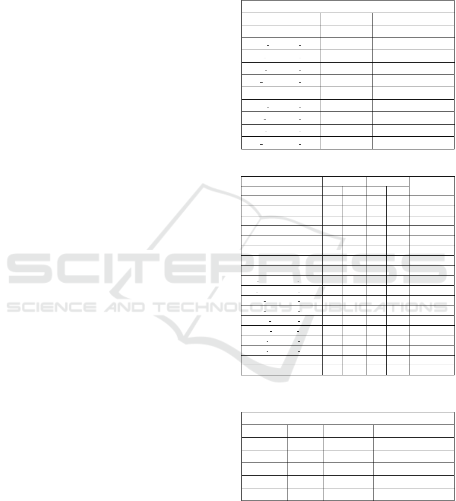
Table 1: Simulation Results using GVT. The corresponding
best results from Table 2 are the denoted by the first number
in the second column; the numbers in brackets denote the
old values from (Rumpe et al., 2015).
Simulation Results (GVT)
test # Time Z3 (ms) Time Isabelle (ms)
CC4 → CC3 251(4766) 326
FLS cc→FLN cc 124(359) 61
FLS lim→FLN lim 251(3156) 499
FLS act→FLN act 109(390) 855
FLS kmh→FLN kmh 798(3364) measurement not taken
CC4 ← CC3 47(0) unsat
FLS cc←FLN cc 109(375) 39
FLS lim←FLN lim 188(3047) 519
FLS act←FLN act 94(391) 860
FLS kmh←FLN kmh 139(0) unsat
Table 2: Global Variable Test evaluation.
None Opt. DNF Opt.
Improvment %
test # time SMTs time SMTs
CC4(r.) → CC3(r.) 734 9 515 7 29,84
CC4(r.) ← CC3(r.) 0 0 16 0 0
CC1(r.) → CC3(r.) 2081 16 2298 30 -10,43
CC1(r.) ← CC3(r.) 2950 33 2271 29 23,02
CC1 → CC3 1749 20 3364 43 -92,34
CC1 ←CC3 3831 48 3035 40 20,78
CC4 →CC3 7156 83 5156 62 27,95
CC4 ← CC3 0 0 79 0 0
FLS kmh(r.) →FLN kmh(r.) 187 3 188 3 -0,53
FLS kmh(r.) ← FLN kmh(r.) 0 0 0 0 0
FLS kmh → FLN kmh 0 0 78 0 0
FLS kmh ← FLN kmh 6711 81 3594 49 46,45
FLS cc → FLN cc 422 6 422 6 0
FLS cc ←FLN cc 406 6 422 6 -3,94
FLS lim → FLN lim 3250 48 3156 48 2,89
FLS lim ← FLN lim 3125 48 3047 48 2,5
FLS act → FLN act 531 8 407 6 23,35
FLS act ← FLN act 578 8 422 6 26,99
Table 3: Execution time before and after the DNF optimiza-
tion is applied.
time, ms
transition # non opt. tree building indexed trans. filtering
10 0 264 0
20 20 9740 10
35 37 17693 20
40 78 31452 40
50 141 78694 100
approach for compatibility verification of Simulink
components. Bounded model checking is used to
conduct behavior compatibility analysis of ANSI-C
program and circuits in Verilog. Software compo-
nent behavior can be transfered into π calculus ex-
pressions to check for compatibility based on be-
havior descriptions (Zhang, 2009). Labeled transi-
MODELSWARD 2018 - 6th International Conference on Model-Driven Engineering and Software Development
264

tion systems are used for compatibility checking for
asynchronously communicating software (Ouederni
et al., 2013). Group transition systems and ABS
modeling language are used to perform model-based
compatibility analysis of software after modifications
(Poetzsch-Heffter et al., 2012).
(Chakrabarti et al., 2002) shows a methodology
of interface compatibility checking for software mod-
ules. The given approach is to use reachability anal-
ysis algorithms on pushdown games. Another ap-
proach for checking behavioral compatibility of in-
terfaces is given in (Wang and Krishnan, 2006). The
work describes developing a Simple Component In-
terface Language (SCIL) that is derived from inter-
face automata. The language allows users to perform
compatibility analysis without having a strong math-
ematical background required to use formal methods.
An approach to checking behavioral compatibility
between web services was described in (CHAE et al.,
2008), it employs an extended version of the conven-
tional methods rule and state machines. Pertri nets
are also used to analyze behavioral similarity of web
services (Li et al., 2011). Open bisimulation, modal
mu-calculus and π calculus are used for formal verifi-
cation of web services (Gao et al., 2006).
In (Dragomir et al., 2016) compatibility analysis
of Simulink components was performed with the Is-
abelle theorem prover. The work presents a tool set
that translates Simulink models into Isabelle theories.
Simulink models are represented as predicate trans-
formers and not as function like in our work. Such
a method has the advantage that it can model com-
ponents that can fail for particular input values, for
example division by zero.
Note that clone detection is a similar task to be-
havior compatibility checking as a cloned component
would exhibit the same behavior whereas two com-
ponents with the same behavior should be detected as
clones.
In (Alalfi et al., 2012b) three types of model
clones are defined:
• Type-1: exact model clones
• Type-2: structurally identical model clones, ex-
cept for variation in labeling (i.e. renamed blocks)
and values types.
• Type-3: model parts (fragments) with changes in
connection or block position, as well as small
amount of additions and removals of blocks.
Block labels and value types can differ (i.e. they
are renamed).
In (Liang et al., 2014) another definition is used to
distinguish between the types of model clones:
1. Syntactic model clones:
• Exact model clones: structurally the same mod-
els
• Approximate model clones: syntactically simi-
lar models, with slight difference in labels, val-
ues or attribute variations, but essentially the
same structure.
2. Semantic model clones: models that have the
same behavior, but rather different structures.
For clone detection several approaches exist in
the literature: In model driven software development,
which is quite often the preferable way of designing
software systems in the automotive field, a cloned
block might result in using more components while
an automobile is getting build, which also means that
the building cost of the product might increase too.
In (Rumpe et al., 2015) a discussion about version
compatibility and maintenance in Simulink models
reveals problems that occur in automotive systems
and how clone detection improves optimization algo-
rithms. Most of the methods and algorithms used to
find clones in software systems aim to find structural
matches, i.e., syntactic clones. As an example we can
point out (Pham et al., 2009) - a graph-based clone
detection tool for Matlab/Simulink models, detecting
both exactly matched and approximate model clones,
(Nguyen et al., 2009) - a structural characteristic fea-
ture extraction tool, (Pham et al., 2009) - a graph-
based clone detection tool for Matlab/Simulink mod-
els, detecting both exactly matched and approximate
model clones, (J
¨
urgens et al., 2009) - a framework for
clone detection, allowing ungapped and gapped clone
detection, using suffix-tree, generated by the program
unit sequence.
Clone detection is also used for solving other
problems, for example in (von Detten and Becker,
2011) an approach combining clustering and pattern-
based detection of mistakes in component-based soft-
ware implementations, in (Abi-Antoun et al., 2006)
an algorithm for comparing and merging C & C ar-
chitectural views, in (Wille et al., 2013) an approach
to analyze related models and determine the vari-
ability between them using structural clone detection,
or in (Stephan and Cordy, 2015) a near-miss cross-
clone detection technique, used to find anti-patterns
in Simulink models.
While there are many implementations adopting
the structural clone detection approach and providing
good results, the number of false positives found by
those methods is still large. In order to increase preci-
sion and find meaningful clones, behavioral clone de-
tection methods have been developed. As an example
for such tools and algorithms we can point out (Alalfi
et al., 2014) - a plugin called Simone, detecting and
representing variability in Simulink models based on
Fast Simulation Preorder Algorithm
265

text-based clone detection, (Antony et al., 2013) - a
tool called NiCad, detecting near-miss clones in UML
behavioral models, by using text-based approach over
XML, (Alalfi et al., 2012a) - near-miss clone detec-
tion, based on transformation of graph-based models
to normalized text form, using Simone plugin as ex-
tension to NiCad tool, (Stephan et al., 2013a) - an-
other paper, describing detection of model clones in
Simulink using Simone plugin to track the evolution
of model clones with respect to their clone contain-
ing classes, (Deissenboeck et al., 2010) - a clone de-
tection tool based on an industrial case study under-
taken with BMW Group, using graph-theory tech-
nique, (Stephan et al., 2013b) - a model-clone de-
tection framework, based on mutation-analysis, using
graph theory, (Stephan et al., 2012) - a brief review
over Simulink model clone detection approaches. Be-
havioral clone detection mostly relies on structural
clone detection tools and algorithms.
9 CONCLUSION
This paper presented several optimization methods
to accelerate compatibility checks of software com-
ponents applied in the automotive field. The con-
ducted experiments indicated that the optimization
undertaken to normalize transition guards of I/O-TS
to Disjunctive Guard-Normal-Form and then to Opti-
mized Hash-Guard-Disjunctive-Normal-Form results
in a decent performance gain of the overall be-
havioral compatibility checking process. Therefore,
this optimization has been included into the Monti-
Matcher framework. Additionally, this paper com-
pared the performance when using the automated the-
orem prover Isabelle as a replacement for Microsoft’s
SMT-Solver. We also show how to generate Isabelle
code to perform compatibility checks and assessed
how Isabelle performed against Z3 solver for these
kinds of application. Though it is still possible to use
Isabelle, the measurements show that the SMT-Solver
Z3 is in most cases faster. Therefore, it is necessary
to search for another appropriate candidate for the
replacement or to endure speed losses, that in many
cases can be critical. We also tried and evaluated an
index tree as a transition filtering mechanism. Unfor-
tunately, while querying the tree shows a better per-
formance than the previously used simpler approach,
the construction process of the tree appeared to be
very slow due to a large number of access operations
during the construction. The optimization removing
internal variables improved, as expected, the speed
of the compatibility checks for mid-scale component
and connector models a lot. In cases when this inter-
nal variable optimization cannot make any statement
on compatibility, it reports fast enough and, therefore,
can be used before the whole execution chain of the
old MontiMatcher tool is invoked.
ACKNOWLEDGEMENTS
Special thanks goes to the two students Vladimir
Parashin and Igor Shumeiko who implemented these
optimizations in their bachelor and master theses su-
pervised by Michael von Wenckstern.
REFERENCES
Abi-Antoun, M., Aldrich, J., Nahas, N. H., Schmerl, B. R.,
and Garlan, D. (2006). Differencing and Merging of
Architectural Views. In ASE.
Alalfi, M. H., Cordy, J. R., Dean, T. R., Stephan, M., and
Stevenson, A. (2012a). Models are code too: Near-
miss clone detection for Simulink models. In ICSM.
Alalfi, M. H., Cordy, J. R., Dean, T. R., Stephan, M., and
Stevenson, A. (2012b). Near-miss model clone de-
tection for Simulink models. In Cordy, J. R., Inoue,
K., Koschke, R., Krinke, J., and Roy, C. K., editors,
IWSC.
Alalfi, M. H., Rapos, E. J., Stevenson, A., Stephan, M.,
Dean, T. R., and Cordy, J. R. (2014). Semi-automatic
Identification and Representation of Subsystem Vari-
ability in Simulink Models. In ICSME.
Antony, E. P., Alalfi, M. H., and Cordy, J. R. (2013). An
approach to clone detection in behavioural models.
In L
¨
ammel, R., Oliveto, R., and Robbes, R., editors,
WCRE.
Baier, C., Katoen, J.-P., and Larsen, K. G. (2008). Princi-
ples of model checking. MIT press.
Bertram, V., Maoz, S., Ringert, J. O., Rumpe, B., and
von Wenckstern, M. (2017). Case Study on Struc-
tural Views for Component and Connector Models. In
MODELS.
CHAE, H. S., LEE, J.-S., and BAE, J. (2008). An Approach
to Checking Behavioral Ccompatiblity Between Web
Services. IJSEKE, 18(02).
Chakrabarti, A., de Alfaro, L., Henzinger, T. A., Jurdzi
´
nski,
M., and Mang, F. Y. C. (2002). Interface Compatibil-
ity Checking for Software Modules. Springer Berlin
Heidelberg, Berlin, Heidelberg.
Deissenboeck, F., Hummel, B., J
¨
urgens, E., Pfaehler, M.,
and Sch
¨
atz, B. (2010). Model clone detection in prac-
tice. In Inoue, K., Jarzabek, S., Koschke, R., and
Cordy, J. R., editors, IWSC.
Dragomir, I., Preoteasa, V., and Tripakis, S. (2016). Com-
positional semantics and analysis of hierarchical block
diagrams. In International Symposium on Model
Checking Software. Springer.
MODELSWARD 2018 - 6th International Conference on Model-Driven Engineering and Software Development
266

Gao, C., Liu, R., Song, Y., and Chen, H. (2006). A Model
Checking Tool Embedded into Services Composition
Environment. In GCC.
J
¨
urgens, E., Deissenboeck, F., and Hummel, B. (2009).
CloneDetective - A workbench for clone detection re-
search. In ICSE.
Li, X., Fan, Y., Sheng, Q. Z., Maamar, Z., and Zhu, H.
(2011). A petri net approach to analyzing behavioral
compatibility and similarity of web services. IEEE
Transactions on Systems, Man, and Cybernetics - Part
A: Systems and Humans, 41(3).
Liang, Z., Cheng, Y., and Chen, J. (2014). A novel op-
timized path-based algorithm for model clone detec-
tion. JSW, 9(7).
Mathworks Inc. (2016). Simulink User’s Guide. Technical
Report R2016b, MATLAB & SIMULINK.
Miller, S. P., Whalen, M. W., and Cofer, D. D. (2010). Soft-
ware model checking takes off. Commun. ACM.
Nguyen, H. A., Nguyen, T. T., Pham, N. H., Al-Kofahi,
J. M., and Nguyen, T. N. (2009). Accurate and Ef-
ficient Structural Characteristic Feature Extraction for
Clone Detection. In Chechik, M. and Wirsing, M.,
editors, FASE, volume 5503 of LNCS.
Ouederni, M., Sala
¨
un, G., and Bultan, T. (2013). Com-
patibility checking for asynchronously communicat-
ing software. In FACS.
Paulson, L. C. (1994). Isabelle: A generic theorem prover,
volume 828. Springer Science & Business Media.
Pham, N. H., Nguyen, H. A., Nguyen, T. T., Al-Kofahi,
J. M., and Nguyen, T. N. (2009). Complete and accu-
rate clone detection in graph-based models. In ICSE.
Poetzsch-Heffter, A., Feller, C., Kurnia, I. W., and Welsch,
Y. (2012). Model-Based Compatibility Checking of
System Modifications.
Reinbacher, T., Kramer, M., Horauer, M., and Schlich, B.
(2008). Motivating Model Checking of Embedded
Systems Software. In MESA.
Rumpe, B., Schulze, C., Wenckstern, M. v., Ringert, J. O.,
and Manhart, P. (2015). Behavioral Compatibility of
Simulink Models for Product Line Maintenance and
Evolution. In SPLC. ACM New York.
Stephan, M., Alalfi, M. H., Cordy, J. R., and Stevenson, A.
(2013a). Evolution of Model Clones in Simulink. In
Pierantonio, A. and Sch
¨
atz, B., editors, Workshop on
Models and Evolution, volume 1090 of CEUR Work-
shop Proceedings.
Stephan, M., Alalfi, M. H., Stevenson, A., and Cordy, J. R.
(2012). Towards qualitative comparison of Simulink
model clone detection approaches. In Cordy, J. R.,
Inoue, K., Koschke, R., Krinke, J., and Roy, C. K.,
editors, IWSC.
Stephan, M., Alalfi, M. H., Stevenson, A., and Cordy,
J. R. (2013b). Using mutation analysis for a model-
clone detector comparison framework. In Notkin, D.,
Cheng, B. H. C., and Pohl, K., editors, ICSE.
Stephan, M. and Cordy, J. R. (2015). Identification of
Simulink model antipattern instances using model
clone detection. In Lethbridge, T., Cabot, J., and
Egyed, A., editors, MODELS.
von Detten, M. and Becker, S. (2011). Combining clus-
tering and pattern detection for the reengineering of
component-based software systems. In Crnkovic, I.,
Stafford, J. A., Petriu, D. C., Happe, J., and Inverardi,
P., editors, ISARCS.
Wang, L. and Krishnan, P. (2006). A framework for check-
ing behavioral compatibility for component selection.
In ASWEC.
Wille, D., Holthusen, S., Schulze, S., and Schaefer, I.
(2013). Interface variability in family model mining.
In SPLC.
Zhang, C. (2009). Software components composition com-
patibility checking based on behavior description. In
GRC.
Zhang, P., Muccini, H., and Li, B. (2010). A classifica-
tion and comparison of model checking software ar-
chitecture techniques. Journal of Systems and Soft-
ware, 83(5).
Zhou, C. and Kumar, R. (2012). Semantic translation of
simulink diagrams to input/output extended finite au-
tomata. Discrete Event Dynamic Systems, 22(2).
Fast Simulation Preorder Algorithm
267
