
Dual-channel Geometric Registration of a Multispectral-augmented
Endoscopic Prototype
O. Zenteno
1
, A. Krebs
2
, S. Treuillet
1
, Y. Lucas
1
, Y. Beneze th
2
and F. Marzani
2
1
PRISME, Universite d’Orleans, F-45072 Orleans, France
2
Le2i FRE2005, CNRS, Arts et M´etiers, Univ. Bourgogne Franche-Comt´e, F-21000 Dijon, France
Keywords:
Gastroendoscopy, Multispectral Imaging, Optical Biopsy.
Abstract:
Multispectral measurement and analysis have proven to be useful to detect and monitor gastric pathologies at
early stages. We developed a multispectral-augmented endoscopic prototype which allows exploration in the
visible and near infrared range (400-1000 nm), increasing the common number of bands under analysis. The
prototype comprises a fiberscope connected to two multispectral snapshot cameras which is inserted through
the instrument channel of a commercial endoscope. However, due to aseptic practices, the system must be
sterilized between exams, forcing physicians to remove and reintroduce it on each examination and leading
to different relative positions between modalities. In the present work, we introduce an axial displacement
correction function for dual-channel registration (i.e., RGB and multispectral) based on the insertion depth of
the fiberscope. The performance was assessed using a chessboard pattern and its corner coordinates as ground
truth. The mean RMSE error of the control points after registration using our method was 2.3 ± 0.7 pixels,
whereas the RMSE error using a frame by frame homographic registration was 1.2 ± 0.4 pixels. In addition,
the technique was tested on mouth exploration samples to simulate in-vivo acquisition. The results reveal
that our method provides similar results when compared to a homographic transformation which would be
impossible to perform in-vivo.
1 INTRODUCTION
Gastric inflammation is an invariable finding in pa-
tients infected with Helicobacter pylori and represents
the host immune response to the organism. It pro-
duces surface epithelial degeneration and infiltra tion
of the gastric mucosa by acute and chro nic inflamma-
tory cells. The prompt detection and diagnosis of gas-
tric inflammation enables the initiation of early-stage
therapy an d can significantly increase the treatment
quality among patients who develop further compli-
cations.
Current endoscopic systems can provide radially
distorted RGB images of the sto mach wall. Howe-
ver, spectral measurem ent and analysis, which pro-
vide accurate quantifications of morphology and mi-
crovascularity, are better to detect and monitor the
progression of these pathologies at an e a rly stage. Se-
veral commercial multispectral imaging approaches
have been proposed to improve g astric exploration.
Typical examples are Fuji Intelligent Chromo En-
doscopy (FICE), proposed by Fuji and Narrow Band
Imaging (NBI), propo sed by Olympus (Song et al.,
2008). These techniques have shown the benefits of
using multiple wavelengths for diagnosis. However
they are limited in the number of wavelengths proces-
sed. We believe that using a larger number of bands in
the visible and near infrared (400-1000 nm) could im-
prove gastro-e ndoscopic exploration and diagnosis.
The common standard in the literature for in- a nd
ex-vivo multispectral exploration is the use of filter
wheels or p ush broom systems, respectively. Howe-
ver, both system s are ineffective for mapping moving
inflamed a reas due to the tempora l lag between wave-
lengths. In contrast, snapshot multispectral systems
can easily acquire reflectan ce data f rom the same area
in all wavelengths simultaneously. The downside of
this type of systems is their low resolution wh ich ex-
tends into small scanning areas.Therefore, it is reaso-
nable to believe that a larger frame of reference in the
image is n eeded. Moreover, the majority of endosco-
pic systems are built-in with a instrument channel into
which different tools (i.e., biopsy sampler, clamp tool,
etc.) can be inserted. This makes it possible to insert
a fibe rscope into this instrument channel. H owever
both modalities nee d to be post-processed and regis-
Zenteno, O., Krebs, A., Treuillet, S., Lucas, Y., Benezeth, Y. and Marzani, F.
Dual-channel Geometric Registration of a Multispectral-augmented Endoscopic Prototype.
DOI: 10.5220/0006721200750082
In Proceedings of the 13th International Joint Conference on Computer Vision, Imaging and Computer Graphics Theory and Applications (VISIGRAPP 2018) - Volume 4: VISAPP, pages
75-82
ISBN: 978-989-758-290-5
Copyright © 2018 by SCITEPRESS – Science and Technology Publications, Lda. All rights reserved
75

tered in order to provide medically relevant informa-
tion. This is not a trivial task, since due to the asep-
tic practices during medica l and surgical proced ures,
the fiberscope mu st be sterilized between exams, for-
cing the physician to remove and reintroduce the fi-
berscope into the instrument channel on each exami-
nation. The procedure leads to different relative posi-
tions between the fiberscope and endoscope for each
new vid eo.
In addition, it is impossible to estimate the r elation
between coordinate systems using calibration patterns
before the insertion of the fiberscope because, du-
ring the medical examination, the physician introdu-
ces first the endoscope into the patient for exploration
and then the fib e rscope into the instrument channel
for localized screening. Thus, registration cannot be
performed with conventional approa c hes (e.g., by ma-
tching singular points). Moreover, once the probe is
inside the patient, the relative position be twe en the
two sensors is not fixed. In fact, two sources of re-
lative movement are present: ro ta tion an d insertion.
Rotation can be neglected if the introduction of the
fiberscope into the endosco pe is contr olled so as to
be performed always in the same position. Howe-
ver, the physician continuously inserts and retracts the
fiberscope during exploration making it necessary to
estimate a real time relation between the two sensors.
Nevertheless the end-tip o f the fiberscop e is vi-
sible throughout the endoscopic exploration. There-
fore, it can be used as a featu re for probe tracking
if it is properly segmented. In the present work, we
introdu ce an axial displacement correctio n fu nction
for the prototype of a multispectral-augmented en-
doscopic system based on the relative position bet-
ween the two cameras. Th e prototype is inten ded to
provide physicians with multispectral (MS) in forma-
tion in small regions of interest overlaid to endoscopic
images with a wider range of vision. Th e remainder
of this document is organized as follow: Section 2
summarizes current related work, Section 3 describes
the system setup and its components, Section 4 pre-
sents the method, Section 5 th e results ob ta ined and
finally Sections 6 and 7 the discussion and conclusion
respectively.
2 RELATED WORK
In the gastrointestinal field, most multispectral and
hypersp ectral (HS) imaging stu dies have involved ex-
vivo biopsies, resected tumor tissues, or organ s such
as the sk in, tongue, or larynx. (Clancy et al., 2012) de-
veloped a laparoscopic HS system based on a liquid-
crystal tunable filter (LCTF), (Martin et al., 2006 )
and (Martin et a l., 2012 ) developed an HS sy stem
with fluorescence for ima ging of the larynx. (D ohi
et al., 2005) used a micro Fabry-Perot interference fil-
ter placed at the tip of a flexible endoscope to cr eate
a wavelength-adjustable spectral endoscope. Nevert-
heless, this ha s not been used clinically yet. (Gale-
ano et al., 2012) an d (Kiyotoki et al., 2013), repor-
ted certain differences observed between healthy and
pre-can c erous ex-vivo colon tissues. However, the
color of the resected sampling tissues differed from
what is nor mally observed in v ivo, which suggests
that the spectral properties of tissue may change after
the resection process. In a recent study, (Martinez-
Herrera et al., 2016) assessed the difference in the in
vivo spectral response of malignant colorectal tumors
and norma l muc osa. Nevertheless, the acquisition sy-
stems u sed a co lor filter wheel, which makes tempo-
ral registration in different wavelengths a non-trivial
task. Therefore, the main challeng e we face is the re-
gistration between the different modalities (i.e. MS
and RGB). Although some solutions for similar pr o-
blems have been implemented in the past, they do not
necessarily aim at quantitative measurements but rat-
her to improve the visual perception of the surgeon
to facilitate handling of the endoscope. For exam-
ple: a non-tracked calibrated endoscope for 3D re -
construction and motion estimation fro m endo-nasal
images was used in (Burschka et al., 2005) to regis-
ter computerized tom ography scans to the endoscopic
video. Another navigation aid using photogramme-
try during endoscopic surgery was studied in (Koppel
et al., 200 4). Here, structural information was used
to prevent the endosco pe image fro m flippin g when
the camera rotates. In (Westwood et al., 2004), the
position of a marked tool inside the surgical scene
was determined from laparoscopic images and used
to cr e ate 3D re nderings from different views fo r the
surgeon. In (Deligianni, 2006), (Scholz et al., 1998),
(Sauer et al., 2002) externally tracked camera s we re
used to augment the surgeon’s view by fusing preope-
rative data with the actual endoscopic view. As men-
tioned befo re, none of them enhance the e ndoscopic
image with MS information.
3 MULTISPECTRAL IMAGING
PROTOTYPE
3.1 Experimental Setup
Figure 1 depicts a diagram of the flexible multis-
pectral gastro-in testin a l prototype, which can be used
to obtain a series of reflected MS image s in a con-
VISAPP 2018 - International Conference on Computer Vision Theory and Applications
76
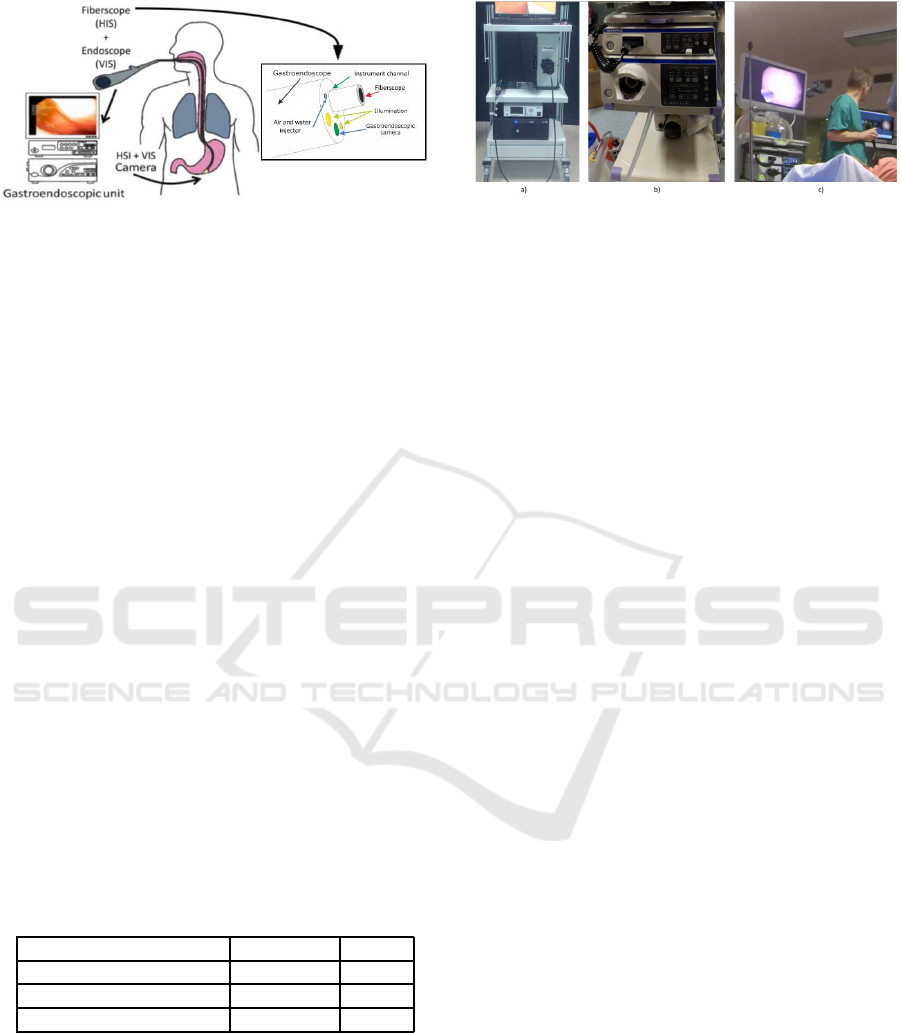
Figure 1: Concept diagram of the multispectral prototype.
tactless manner in the wavelength range of 470 to 975
nm.
The system c omprises six units: a mercury (Xe-
non) light source, an endoscop e imaging unit, a visi-
ble (VIS) range multispectral camera, a Near Infrared
(NIR) range multispectral camera, a fiberscope and
a twin-cam camera splitter. IT was implemented as a
modification of the commercialized Olympu s (Tokyo,
Japan) EVIS EXERA III endoscopic system by in-
troducing an ITConcepts (Lahnau , Germany) microf-
lex m2.5-2500 fiberscope in the instrument channel
for dual simultaneous exploration. The fiberscope is
connected at one side to a Cairn research (Kent, UK)
TwinCam camera splitter by an optical adaptor and
at the other to a mercury (Xenon) light source unit
from Oriel Instruments (California, USA). Finally,
the VIS range camera MQ022HG-IM-SM4X4-VIS
and the N IR camera model MQ022HG-IM-SM5X5-
NIR f rom Ximea (Munster, Germany) are connected
to both ends of the splitter respectively. Figure 2
depicts the multispectral system including the light
source, TwinCam system and fiberscope (left), the en-
doscopic system including the light source, proces-
sing system and endoscope (center) and an example
of data acquisition using the prototype (right). The
detailed spec ifica tions of the three cameras are pre-
sented in Table 1.
Table 1: Camera specification.
Camera Resolution Bands
XIMEA SM5X5-NIR 409x216 25
XIMEA SM4X4 -VIS 512x256 16
OLYMPUS EX ERA III 720x576 3
3.2 Acquisition Interface
A custom user inte rface was developed for data acqui-
sition. The interface allows the user to capture the se-
quence of raw multispectra l images and the gastroen-
doscopic video stream simultaneously. The three ca-
meras mu st be connected to the computer. The en-
doscope is connected through a firewire interface and
Figure 2: Experimental setup: (a) multispectral system, (b)
endoscopic system, (c) in-vivo acquisition.
the multispectral cameras are connected via USB 3.0
interface. Currently the interface captures two ima-
ges per second due to the exposure time required for
the multispectral system. However, the interface is
intended to be able to captu re at the same frame rate
as the endoscope (e.g., 25FPS). The complete proces-
sing pipeline of the images is currently done off-line
(i.e., image matching, filtering, spectral a nalysis).
4 METHODS
To estimate the co rrection function and c alibration of
all the cameras at the same time, we used a comm on
chessboard pattern of 17x15 squares of 1 mm. with
an isosceles triangle in its center. The pattern allo-
wed us to establish a relation between the geometri-
cal coordinates of the two systems through a discrete
measurement of how the triangle and its sur roundings
translate and expand in the image at different inser-
tion depths. The proposed methodology is divided in
five stages: Pre-processing, camera calibration, cont-
rol point selection, parametric correction, and multis-
pectral image enhancement. The first four are execu-
ted off-line and only once as pa rt of a training phase.
The la st one can be executed in dependently, also off-
line, at any time using the previously saved images.
The correction transformation (C
n
) where n is the
selected frame can be formalized as a multiple se-
quential transformation matrix (as shown in Eq. (1))
composed by homographic (H
0
), scaling ( S
n
) and
translation (T
n
) transformations. (H
0
) is calculated
only on ce during the training stage and is continu-
ously used as the initial transformation at any depth.
S
n
and T
n
are estimated for each frame and are linearly
dependent on the de te cted insertion distance.
C
n
= H
0
∗ S
n
∗ T
n
(1)
C
n
=
h
11
h
12
h
13
h
21
h
22
h
23
h
31
h
32
h
33
s
x
1 1
1 s
y
1
1 1 1
1 1 t
x
1 1 t
y
1 1 1
Dual-channel Geometric Registration of a Multispectral-augmented Endoscopic Prototype
77
4.1 Data Preprocessing
The raw images acquired from the multispectral sen-
sors have to be preprocessed to remove noise and un-
wanted a rtifacts (i.e., the moire effect or honeycomb
patterns) produced by the disposition of fibers. Af -
ter acquiring sequential MS images containing diffe-
rent spectral information, we performe d image pre-
processing to reduce imperfections that arose during
imaging and to generate images suitable for analysis.
Noise reduc tion, contrast enhanceme nt and illumi-
nation normalization were performed using commo n
homomorphic filtering and de-vign e tting tech niques
(Georgieva, 2015) and (Nair and Govindan, 2014).
4.2 Dual Camera Calibration
Camera calibration is divided in two phases (i.e., spa-
tial and spectral calibra tion). The first is applied be-
fore registration and th e latter can be applied after re-
gistration for spectral data analysis. The spatial cali-
bration was performed using MATLAB’s built-in ca-
mera calibration toolbox which is a modified version
of the method presented in (Bouguet, 2000). This
method uses the pin-hole camera model. The initial
estimation o f the planar homographies is based on the
method presented in (Zhang, 1999) and the closed-
form estimation of the internal pa rameters was per-
formed using orthogonality of vanishing points. The
intrinsic mode l was similar to the on e presented in
(Heikkila and Silven, 1997). The spectral calibration
was performe d using a color matrix. With this ma-
trix, a set of images with known spectral response was
acquired to estimate the required linear transforma-
tion from raw data into real multispectral reflectance.
A set of endoscopic a nd mu ltispectral (fiberscope)
images b efore and after geometrical correctio n are
presented in Fig 3.
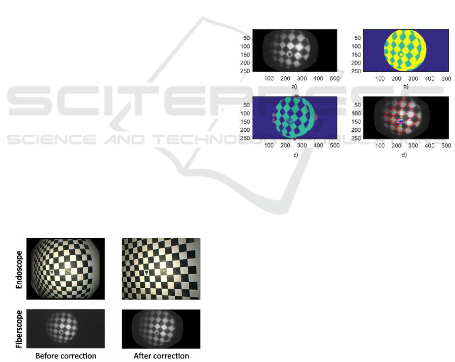
Figure 3: Endoscopic and fiberscopic images: Before (left)
and after (right) radial distortion correction.
4.3 Control Point Detection and
Selection
The training homographic registration was per formed
using a initial grid of common points betwee n the
two undistorted modalities. T he initial grid identi-
fication is executed in four steps; the complete pro-
cess is depicted in Fig 4. First, an adaptive histogram
equalization is applied on the pattern’s image to en-
hance the dynamic range.Then, automatic threshol-
ding and morphological operations a re performed in
order to obtain single Binary Large Objects (BLOB).
After this, each BLOB is analyzed to find common
characteristics to differentiate between triangles and
rectangles (Number of vertices, extrema distribution
and area relations). After identification of the cen-
tral triangular pattern, the four proximate corners are
identified ba sed on their relative Euclidean distance.
Finally, a new reference axis is defined based on the
location of each triangle vertex.
Figure 4: Pattern identification and creation of new axis on
fiberscopic images. (a) Histogram equalization, (b) Thres-
holding, (c) BLOB analysis, (d) New reference axis cente-
red in the triangle vertex.
After the new axial reference has been define d a
common set of control points is identified in the two
images. This is based on two-dimensional exploratio n
of the p oint grid and intersection of coordinate points
(as shown in Fig 5). The discrimination criteria con-
sists in maximizing the nu mber of common detected
corners starting from the new origin and expa nding to
the four cardinal points of the new coo rdinate system.
The final projective transform matrix is calculated
as the homogra phy between the two set of coordinate
points. Due to the different size and resolution of the
images a new global coordinate system is applied to
the scaled fiberscopic image .
4.4 Parametric Correction Model
The estimation of the correction function is divided
in two steps: Insertion measurement and estimatio n
VISAPP 2018 - International Conference on Computer Vision Theory and Applications
78
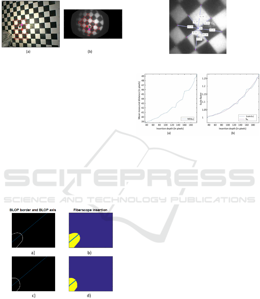
Figure 5: Common grid creation on the new axis on (a)
endoscopic images, (b) fiberscopic images.
of the transformation matrix. Bo th steps are initially
performed on a training set consisting of 15 endosco-
pic and 15 multispectral images, each one with the
fiberscope at a different insertion depth. To measure
this depth during exploration the depth of the tip in
the color images is tr acked. As the present study fo-
cuses particularly on the relation between depth and
transformation, we dec ided to perform manual seg-
mentation of the fiberscope tip to guar antee the hig-
hest measurement p recision possible. Further seg-
mentation techniques need to be explored after vali-
dation. The depth measurement procedure is depicted
in Fig.6. First, the resulting BLOP from the segmen-
tation is initially fitted to an ellipsoid an d its two axes
are calculated. T he ellipsoid’s horizontal axis is then
projected into infinity. Finally, the Euclidian distance
between the intersections of the projected line w ith
the borders of the segmented BLOB and the left la te -
ral limit of the image is measured in pixels.
Figure 6: (a),(c): Segmentation of the fiberscope tip and
(b),(d): BLOP’s axis intersection measurement.
For the transformation m a trix estimation, we ana-
lyzed the mean of the distances from the center of
the triangle to 8 points in the borders of the central
2x2 pattern on all the images in the data base. Fig
7. depicts the eight c orners, the center of the pattern
and the distance between each of them on a sample
Figure 7: Measurement of distances to the center of the 2x2
central pattern.
Figure 8: Relation graphs between i nsertion depth and: (a)
mean measured distance, (b) normalized scaling factor.
fiberscopic fram e . We used this information to evalu-
ate the relation between the insertion depth and how
the mean distance between c orners and center scales
through different frames.To estimate the scaling fac-
tor, a normalization o f the measured distance based on
the first sampling frame was performed. After this, a
quadra tic fit was applied to obtain a function of sca-
ling based on dep th (Fig. 8).
However, the cen tral axis of the tra nsformation
was not always located in the center of the image.
Therefore, the center of the displacement needed to be
measured fr ame by frame based on the locatio n of the
center on the triangle from the pattern. This measure-
ment was also c ompared to the insertion depth and fit-
ted to a qua dratic function correspo nding to each a xis.
The corresponding functio ns for the x and y axes are
shown in Fig. 9.
In addition, the scaling and translatio n correction
functions (i.e., s
n
, t
x
n
and t
y
n
) are forma lize d as a
function of the insertion depth (d
n
) as sh own in Eq.
(2),(3) and (4).
s
n
= 8.8x10
−6
d
n
2
− 5x10
−4
d
n
+ 1 (2)
t
x
n
= 2x1 0
−3
d
n
2
− 9.4x10
−2
d
n
+ 0.52 (3)
t
y
n
= 1.5x10
−3
d
n
2
− 6.6x10
−2
d
n
− 0.055 (4)
Dual-channel Geometric Registration of a Multispectral-augmented Endoscopic Prototype
79
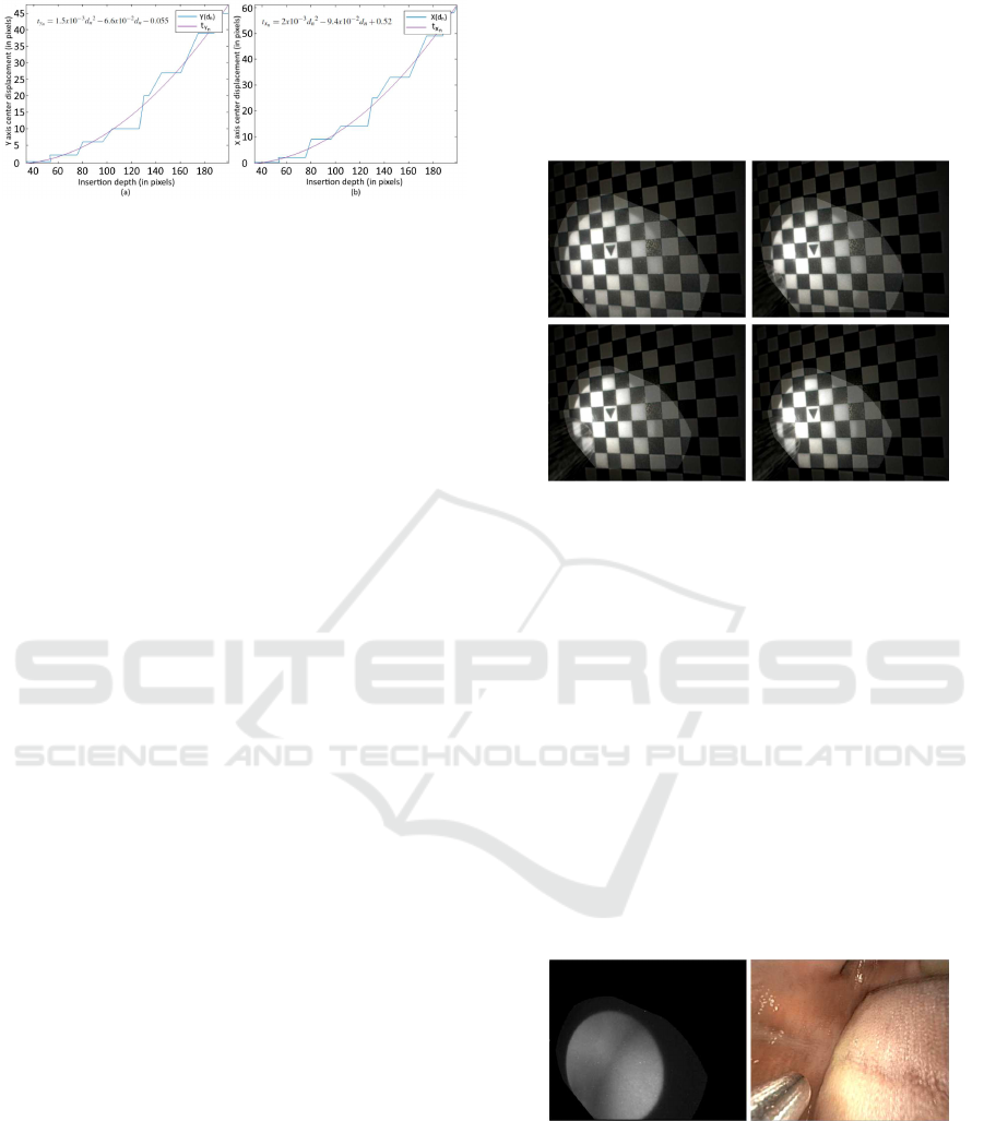
Figure 9: Relation graph between insertion depth and: (a)
x-axis translation, (b) y-axis translation.
4.5 Multispectral Enhancement
Finally, once the correction functions have been es-
timated the fiberscope-to-endoscope registered image
I
r
can be performed at any continuous point on the
insertion d e pth range. This is done by replacing the
values of the scaling and translation factor s
n
and t
n
obtained from Eq . (2) , ( 3) and (4) in the correction
transformation described in Eq. (1) and applying it to
the original image I
o
as follows:
x
′
y
′
1
I
r
= T
n
∗ S
n
∗ H
0
∗
x
y
1
I
o
, where (5)
S
n
=
s
n
1 1
1 s
n
1
1 1 1
and T
n
=
1 1 t
x
n
1 1 t
y
n
1 1 1
4.6 Performance Assessment
The performance test was executed using a chessbo-
ard pattern as sample and the coordinates of its cor-
ners as gr ound truth. The test sample comprised 2 5
MS and endoscop ic frames in which the fib e rscope
is at different insertion depths. The fiberscope is al-
ways observable in the endoscopic image. For eva-
luation, the mea n RMSE error and standard deviation
(when compared to the ground truth coordinates) on
each corner of the pattern after registration with our
method were compared to those obtained whe n using
a fram e-by-frame homograph ic registration. In addi-
tion, the registration was also tested on mouth explo-
ration samples to simulate in-vivo acquisition. In all
cases, the acquisition on all cameras was performed
simultaneou sly
5 RESULTS
An example of the registration results is depicted on
Fig. 10. Four different r egistered fiberscope and
endoscope image overlays at a different position of
the fiberscope for each frame are shown. The en-
doscopic image appears in the background in a dar-
ker tone, while the transformed fiberscopic ima ge ap-
pears highlighted. While observing the images it is
easy to recognize the progressive transformation of
the fiberscopic image at different depths.
Figure 10: E xamples of registered images where the fi-
berscope is at different depths.
Performance statistics for e a ch set of ima ges are
presented in Table 2. The mean RMSE error bet-
ween ground-truth coordinate poin ts and the resulting
transformed coordinates using frame-by-frame homo-
graphy and our correction transformation matrix were
1.2 ± 0.4 and 2.3 ± 0.7 respectively.
In addition, the qualitative performance of the pro-
posed method on mouth sam ples revealed a high level
of coherence between the registered images. Figure
11 depicts a sample frame of the resulting video. The
registered spectral information of a single wavelength
and a frame of a mouth exploration endo scopic video
are presented on the left and right of the image re-
spectively. Although the data of a single band is not
enoug h to characterize the tissue, the image illustrates
the pote ntial o f the techniq ue for in-vivo applicatio ns.
Figure 11: Qualitative results on in-vivo mouth samples.
6 DISCUSSION
The results are enc ouraging. Visually, the registered
pattern fits seamlessly into the endoscopic image at
different insertion depths. Statistically, the error in all
cases was lower than 4 pixels. AS the resolution of
VISAPP 2018 - International Conference on Computer Vision Theory and Applications
80

Table 2: Comparison of the performance of control point
homography vs the proposed method.
Frame H
n
RMSE C
n
RMSE
1 0.9 3.1
2 1.2 2.6
3 1 3.3
4 1 3.2
5 1.7 3.8
6 1.1 3.1
7 1.2 2.7
8 0.9 3.1
9 0.9 2.1
10 1.1 1.8
11 1.2 2.2
12 0.9 1.9
13 1.4 2.1
14 1.3 1.8
15 1. 2
16 0.8 2.5
17 1 1.7
18 2.3 2.5
19 1 2
20 2 1.7
21 1.2 1.5
22 1 1.2
23 1.5 1.7
24 1.1 1.1
25 1.2 1.9
MEAN 1.2 ± 0.4 2.3 ± 0.7
the endoscopic images is 726x576p, a 2-3 pixel e rror
is less than 1% o n each dir ection. Moreover, the sim-
plicity of the proposed pipeline and the use of com-
mon image processing tools make it ideal for future
real-time implementations.
However, althou gh the presented method has pro-
ven to effectively correct the difference between the
relative position of the two c amera axes, some limita-
tions are still present. First, in the current impleme n-
tation the insertion of the endoscope was controlled to
ensure that it was always performed in the same posi-
tion. Even though it is a trivial task, it would be ideal
to relieve the physician of this constraint. The rotati-
onal problem can be easily solved by performing an
affine transformation. However, we have not yet been
able to identify a marker which can be used to mea -
sure the degrees require d in the rotation. Secondly,
we detected a thir d source of movement which we
call precession th at is produced by the circular mo-
vement of the fiberscope through the small surroun-
ding space between the endoscope and the fiber. Furt-
her exploration of the effects of precession in a wi-
der range of positions should be carried out. Thirdly,
the correction functio n will always be system depen-
dent, this means that the initial discrete homography
process should always be executed if the physician
changes the endoscope or video system. However, if
the video system is modified, a camera calibration is
always requ ired and the two processes (i.e., calibra-
tion and correction) can be performed simultaneously
with similar data. Fina lly, the current f rame rate of the
multispectral system is two images per second. This
may produce motion artifacts intr oduced by either the
probe operator or target movement and is not id e al to
perform in-vivo acquisitions.In contrast, the endo sco-
pic video frame rate is much higher with the standard
25 images per second. Further development is being
performed in the interface on a real-time implementa-
tion of these steps, which will not only overlaid single
endoscope images but will also be able to show real
time spectral information to physician s. Also, a re al
gastro-endoscopic sample is required for further ex-
ploration of the spectral data.
7 CONCLUSIONS
This paper has presented a method for com pensa-
tion o f the insertion and retraction motion of a fi-
berscope inserted in the instrument channel of an en-
doscope by using simple geometrical transformati-
ons. The technique relies o n applying a linear affine
transformation over a one-time c ontrol point homo-
graphy. Manual segmentation of the fiber scope in the
endoscopic images is performed for precise estima-
tion of the position and orientation of the fiberscope
camera. Experimental results using real endoscopic
images showed that the method can track the camera
insertion and retraction motion. Although the pipelin e
is cur rently executed off-line, this pa per demonstrates
the potential of ima ge-based tracking of a fiberscope.
The incorporation of more degrees of freedom in the
proposed method m ay enable us to achieve real-time
and ro bust tracking in the future.
ACKNOWLEDGEMENTS
The au thors would like to thank M.D. Dominique La-
marque, for his assistance in mouth data acquisition
and endoscope handling. This work was supported
by the EMMIE (Endoscopie MultiMod a le pour les
l´esions Inflammatoires de l’Estomac) project funded
by the ANR-15-CE17-0015 grant.
Dual-channel Geometric Registration of a Multispectral-augmented Endoscopic Prototype
81

REFERENCES
Bouguet, J.-Y. (2000). Matlab camera calibration toolbox.
Caltech Technical Report.
Burschka, D., Li, M., Ishii, M., Taylor, R. H., and Hager,
G. D. (2005). Scale-invariant registration of mono-
cular endoscopic images to ct-scans for sinus surgery.
Medical Image Analysis, 9(5):413–426.
Clancy, N. T., Stoyanov, D., James, D. R., Di Marco, A.,
Sauvage, V., Clark, J., Yang, G.-Z., and Elson, D. S.
(2012). Multispectral image alignment using a three
channel endoscope in vivo during minimally invasive
surgery. Biomedical optics express, 3(10):2567–2578.
Deligianni, F. (2006). VISUAL AUGMENTATION FOR
VIRTUAL ENVIROMNENTS IN SURGICAL TRAI-
NING. PhD thesis, Imperial College London.
Dohi, T., Matsumoto, K., and Shimoyama, I. (2005). The
micro fabry-perot interferometer for the spectral en-
doscope. In Micro Electro Mechanical Systems, 2005.
MEMS 2005. 18th IEEE International Conference on,
pages 830–833. IEEE.
Galeano, J., Jolivot, R., Benezeth, Y., Marzani, F., Emile,
J.-F., and Lamarque, D. (2012). Analysis of multis-
pectral images of excised colon tissue samples based
on genetic algorithms. In Signal Image Technology
and Internet Based Systems (SITIS), 2012 Eighth In-
ternational Conference on, pages 833–838. IEEE.
Georgieva, V. (2015). Homomorphic filtering approach for
narrow band i mages enhancement. Journal of Applied
Electromagnetism (JAE), in print.
Heikkila, J. and Silven, O. (1997). A four-step camera ca-
libration procedure with implicit image correction. In
Computer Vision and Pattern Recognition, 1997. Pro-
ceedings., 1997 IEEE Computer Society Conference
on, pages 1106–1112. IEEE.
Kiyotoki, S., Nishikawa, J., Okamoto, T., Hamabe, K.,
Saito, M., Goto, A., Fujita, Y., Hamamoto, Y., Ta-
keuchi, Y., Satori, S., et al. (2013). New method
for detection of gastric cancer by hyperspectral ima-
ging: a pilot study. Journal of biomedical optics,
18(2):026010–026010.
Koppel, D., Wang, Y.-F., and Lee, H. (2004). Image-based
rendering and modeling in video-endoscopy. In Bio-
medical Imaging: Nano to Macro, 2004. IEEE Inter-
national Symposium on, pages 269–272. IEEE.
Martin, M. E., Wabuyele, M. B., Chen, K., Kasili, P., Pan-
jehpour, M., Phan, M., Overholt, B., Cunningham, G.,
Wilson, D., DeNovo, R. C., et al. (2006). Develop-
ment of an advanced hyperspectral imaging (hsi) sy-
stem with applications for cancer detection. Annals of
biomedical engineering, 34(6):1061–1068.
Martin, R., Thies, B., and Gerstner, A. O. (2012). Hyper-
spectral hybrid method classification for detecting al-
tered mucosa of the human larynx. International jour-
nal of health geographics, 11(1):21.
Martinez-Herrera, S. E., Benezeth, Y., Boffety, M., Emile,
J.-F., Marzani, F., Lamarque, D., and G oudail, F.
(2016). Identification of precancerous l esions by mul-
tispectral gastroendoscopy. Signal, Image and Video
Processing, 10(3):455–462.
Nair, J. J. and Govindan, V. (2014). Intensity inho-
mogeneity correction using modified homomorphic
unsharp masking. Journal of Medical Imaging and
Health Informatics, 4(2):285–290.
Sauer, F. , Khamene, A., and Vogt, S. (2002). An augmented
reality navigation system wi th a single-camera trac-
ker: System design and needle biopsy phantom trial.
Medical Image Computing and Computer-Assisted In-
terventionMICCAI 2002, pages 116–124.
Scholz, M., Konen, W., Tombrock, S., Fr icke, B., Adams,
L., Von Duering, M., Hentsch, A., Heuser, L., and
Harders, A. (1998). Development of an endoscopic
navigation system based on digital image processing.
Computer Aided Surgery, 3(3):134–143.
Song, L. M. W. K., Adler, D. G., Conway, J. D., Diehl,
D. L., Farraye, F. A., Kantsevoy, S. V., Kwon, R ., Ma-
mula, P., Rodriguez, B., Shah, R. J., et al. (2008). Nar-
row band imaging and multiband imaging. Gastroin-
testinal endoscopy, 67(4):581–589.
Westwood, J. et al. (2004). Reconstruction and enhan-
cement in monocular laparoscopic imagery. Medi-
cine Meets Virtual Reality 12: Building a Better You:
the Next Tools for Medical Education, Diagnosis, and
Care, 98:37.
Zhang, Z. (1999). Flexible camera calibration by viewing
a plane from unknown orientations. In Computer Vi-
sion, 1999. The Proceedings of the Seventh IEEE In-
ternational Conference on, volume 1, pages 666–673.
Ieee.
VISAPP 2018 - International Conference on Computer Vision Theory and Applications
82
