
Component-based Modeling in Umple
Mahmoud Husseini Orabi, Ahmed Husseini Orabi and Timothy C. Lethbridge
School of Electrical Engineering and Computer Science, University of Ottawa,
800 King Edward Avenue, Ottawa, Canada
Keywords: Umple, Active Object, Composite Structure, UML.
Abstract: Modelling tools provide weak or no support for the rich semantics of composite structure, such as enforcing
connection constraints and maintaining referential integrity. Tools that generate code from composite
structure typically depend on excessive and complex internal class representations such as Actor or BasePort.
In this paper, we present easy-to-comprehend syntax describing composite structure in Umple. We describe
a novel protocol-free approach that dynamically extracts communication protocols as a way to ease
component-based modelling, and lead to concise and optimized code generation. We outline Umple
composite structure features, and the related code generation patterns that resolve difficulties around
connections and the integrity of multiplicity constraints.
1 INTRODUCTION
Composite structure development refers to the
implementation of concurrent components that
interact and communicate via ports and connectors
(Orabi, Orabi, & Lethbridge, 2016).
In UML, interactions among components are
handled as messages and signals. There are two
message-passing actions, one-way call
(asynchronous call) and calls that block waiting for a
response (synchronous call). An asynchronous call is
referred to as a one-way message passing, since it
does not support a scheduling mechanism to receive
results. Typically, events are triggered when
receiving messages by invoking a corresponding
method. Event handling is often done in a
component's state machine.
Handling message flow among ports and
components usually depends on protocols. Typically,
defining a protocol involves repetitive steps with
redundant information to define how in and out
events are managed. Hence, complexity is added to
the development process.
Open-source tools such as eTrice and ArgoUml
do not support all the major features of composite
structure (Orabi et al., 2016). On the other hand,
commercial tools that provide strong support to
composite structure typically restrict users to certain
libraries, such as Connexis, which is tightly integrated
with RSARTE (Lakkimsetti, 2014).
Motivated by the above, we show how we extend
Umple, an open-source tool, to support composite
structure and overcomes such limitations.
Umple is a text- and model-oriented
programming language that allows for generative
programming using many target languages such as
C++, Java, and PHP (Badreddin, Forward, &
Lethbridge, 2014; Badreddin, Lethbridge, &
Forward, 2014; Lethbridge, Abdelzad, Husseini
Orabi, Husseini Orabi, & Adesina, 2016; Orabi et al.,
2016). Umple implements the core features of UML,
such as state machines, associations, and attributes. In
addition, Umple provides other usable features to
ease development such as traits, mixins, and aspect-
orientation. The selected target language in this paper
is C++. Umple features can be fully tried and tested
using the UmpleOnline website (try.umple.org).
Our key contributions can be summarized as
follows:
• We support major composite structure features
using compact keywords and shortened syntax.
• We provide generic extensible communication
and transport definitions to support distributed
examples. We implement support for the
TCP/UDP communication protocol and JSON as
a message interchange format to be the default
medium for communication among distributed
components.
Orabi, M., Orabi, A. and Lethbridge, T.
Component-based Modeling in Umple .
DOI: 10.5220/0006715902470255
In Proceedings of the 6th International Conference on Model-Driven Engineering and Software Development (MODELSWARD 2018), pages 247-255
ISBN: 978-989-758-283-7
Copyright © 2018 by SCITEPRESS – Science and Technology Publications, Lda. All rights reserved
247
• We incorporate the active object pattern
(Lavender & Schmidt, 1996) to extend and
enable the request-scheduling mechanism.
• We implement a protocol-free approach, in
which protocols are inferred from ports,
connectors, and components.
• Our implementation works for distributed
applications, and does not restrict users to certain
network paradigms or any particular transport
data format.
Composite structure features are introduced to
Umple as a part of this research, as a major step
towards the development of connected embedded
devices.
2 COMPONENT-BASED
MODELLING AND
STANDARDS
Many of the existing component-based modelling
tools (Orabi et al., 2016) adapt specifications such as
UML (OMG, 2011), SysML (Mallet, Peraldi-Frati, &
André, 2009), Specification and Description
Language (SDL), and Real-time Object-Oriented
Modelling (ROOM) (Selic & ObjecTime, 1996).
In our work, we are more inspired by UML, since,
1) OMG uses UML as the de facto modeling notation
for object-oriented systems (Grady Booch, James
Rumbaugh, 2005), and 2) UML is well-known for
design specification for real-time systems, especially
embedded devices. As well, in terms of real-time
modelling, we follow many of the ROOM
specifications. However, we have an extended the
active object pattern to handle concurrency (Orabi,
2017).
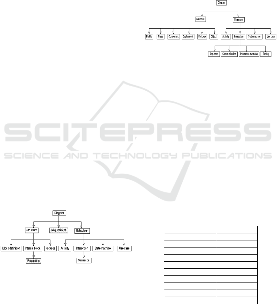
Figure 1: SysML diagram types.
Additional SysML diagrams, as compared to UML are
highlighted
SysML provides a lightweight profile of UML in
terms of aspects such as stereotypes, constraints, and
tagged values; hence, it can ease and reduce UML
restrictions, and support a wide range of systems,
either software or hardware.
SysML only uses seven of the UML diagrams
(Figure 1) in addition to two diagram types,
requirement and parametric (Figure 2). A class
diagram is called a "block definition" diagram and a
component (composite) structure diagram is called an
"internal block" diagram.
Figure 2: UML diagram types.
SDL’s main purpose is to provide unambiguous
software system specifications (Olsen, Færgemand,
Møller-Pedersen, Smith, & Reed, 1994). SDL has
mainly been used in the modeling of real-time
communication systems. It provides similar
functionality as UML but with different terminology
and notation (Table 1).
ROOM was developed by ObjectTime and
introduced in the ObjectTime Developer Tool (ODT)
(Selic & ObjecTime, 1996). ROOM incorporates a
variant of Harel's statecharts. In 1996,
RoomLanguage represented the actor as the primary
element that communicates with other elements using
port interfaces. A port is an instance of a protocol
class that defines the message communication
between actors. The concept of Actor was later
referred to as a Capsule in UML-RT. ROOM supports
hierarchical modeling and incremental refinement of
complex behaviour.
Table 1: UML to SDL term mapping.
UML
SDL
Class
Type
Interface
Interface
Associations
Channels
Operations
Signal List
Variable
Attribute
Sub
Block
Abstract
Abstract
Implementation
Process
Type
Gate
Inheritance
Inheritance
MODELSWARD 2018 - 6th International Conference on Model-Driven Engineering and Software Development
248

3 COMPOSITE STRUCTURE IN
UMPLE
In Umple, components, ports, and connectors are
used to describe structural implementation of an
object, while state machines are used to define its
behaviour. A component is viewed as an active object
entity with a unique identifier (UID) that handles its
own thread of execution and encapsulates its well-
defined behaviour.
The implementation of composite structure in
Umple uses an extended version the active object
pattern (Orabi, 2017). In Umple, an active object class
is referred to as a component. Communication among
components is established via ports and connectors,
with necessary protocols being internally generated
and hidden from the developer.
Each component has a public interface, UID,
internal router, connection type, and transport data
format. An internal router is used to manage
components in a distributed system.
We use template meta-programming (TMP) to
avoid stub generation, reduce the volume of code the
user has to write, and provide an extensible
communication stack (Orabi, 2017; Smaragdakis &
Batory, 2000).
The public interface refers to the methods
exposed for communication, which can be
synchronous, asynchronous, or future asynchronous.
They are internally represented as a generic template
proxy that enables a publish-subscribe mechanism,
and uses the internal router of their owning class.
Standard public methods are synchronous, while port
public interface methods are asynchronous. A special
case is future asynchronous, which represents an
active method with a return type. This means that in
the distributed mode, a component that initiates future
asynchronous calls is going to receive a scheduled
response asynchronously from the other component.
A component handles both inter-process
communication (IPC) and remote method invocation
(RMI). The internal routing structure provides the
essential blocks to ease the building of components
that can communicate. The internal routing table is
used to handle send-reply and request-scheduling
mechanisms between component's internal methods
and respondents. A component can be either in local
or distributable state. Being in distributable state
means that either the component is listening (acting
as a server) or initiating communication (acting as a
client). There is no restriction to a specific network
paradigm or multi-party communication.
A communication stack provides abstract
definitions for connection mechanisms and data
interchange transport formatters. By default, we
support TCP/IP as a connection mechanism, and
JSON as a data interchange format. The code can be
easily extended to support different connection
mechanisms such as UDP and Bluetooth, and other
formats such as XML.
3.1 Components and Parts
A class becomes a component if it has at least one
active method, port, or connector. An active method
is defined as a regular method proceeded by the active
keyword (Snippet 1 - Lines 2 and 9). When invoking
an active method, it executes asynchronously, since it
has its own thread.
1
2
3
4
5
6
7
8
9
10
11
12
13
14
15
16
17
18
class A { // A component
Umple
active method1 {
cout <<"Method without parameters"
<< endl;
}
}
class B {
active method2 (int someParam) {
cout << " Parameter value"" <<
someParam <<endl;
}
}
class C {
A a;
B b;
}
Snippet 1: An example of a component definition.
A part, or subcomponent, is an instance of a
component, and it is owned by the component
structure of some component. The instance type of a
part, or subcomponent, can be the same as its owning
component; this is similar to the programming
patterns, in which an instance of a class is created in
that class's definition in places such as constructors,
attributes, or methods. When a component owns
multiple parts, it is referred to as a composite
component. A subcomponent can possibly be
composite. A component has a composition
relationship to each class typed by its owned parts.
Figure 3: Multiple instances of different components.
Component-based Modeling in Umple
249

In Figure 3, the parts "a" and "b" are instances of
A and B respectively, and they are owned by a
component "c" of the type C. The Umple code is in
(Snippet 1; see definitions of classes A, B, and C).
This means that C has composition relationships to A
and B.
3.2 Ports
A port in Umple is defined as an attribute, and
additionally has a direction, which can be in, out, or
both (specified using the keyword port and meaning
bi-directional, and also referred to as dual). A port
attribute is lazy. In Umple, lazy attributes are not
initialized through their owning class’s constructor.
The keywords in, out, and port are used to set a
port direction (Snippet 2 - Lines 2-4).
1
2
3
4
5
6
7
8
9
10
11
12
13
14
15
16
17
18
19
20
21
22
23
24
25
26
27
28
29
30
31
32
33
34
class Component{
Umple
in Integer inPort;
out Integer outPort;
port Integer dualPort;
internal in Integer privatePort;
in SomeClass someComplexPort;
port CompoundPort compoundPort;
CompoundPort
active compoundPort_ActiveMethods(){
[someInPort]
active void handleDefaultDirection(){}
->handleConjugatedDirection(){
// CompoundPort inversion is as below
//out Integer someInPort;
//int Integer someOutPort;
}
}
void active someMethod(){
stateEvent(pIn1 + 1);
}
pIn1Statemachine{
receive{
stateEvent(int val) /{cout<< val;} ->done;
}
done {}
}
}
class SomeClass{}
class CompoundPort{
in Integer someInPort;
out Integer someOutPort;
}
Snippet 2: Port examples.
A port has visibility since it is defined as an
attribute. A private attribute in Umple is defined using
the internal keyword (Snippet 2 - Line 5); by default,
an attribute is public (Snippet 2- Lines 2-4). Private
ports can only be accessed by their owning
component.
A port can be simple, complex, or compound. A
port is simple if its attribute type is simple such as
string, integer, or double (Snippet 2- Lines 2-5);
otherwise, it is considered complex (Line 6). A
compound port consists of a number of subports, as a
way to encompass a number of events for
transmission (Lines 7, 8, and 30-33).
A port attribute type has no restrictions. For
instance, a port attribute can be typed by a
component.
Within a component-based application,
communication is established among a number of
components instances. The boundary of instances
created is managed using class associations, similarly
to any normal application (Snippet 3 - Line 7).
Messages propagated will be received by all instances
associated (Line 23).
3.3 Connectors
A connector associates between two ports in order to
establish a communication channel for data
transmission. A class is considered a component if it
has a connector defined, even if this class does not
own active methods or ports.
1
2
3
4
5
6
7
8
9
10
11
12
13
14
15
16
17
18
19
20
21
22
23
24
25
class Client{
Umple
in String cp;
}
class Server{
out String sp;
* -- * Client; //Many to many association
}
class Sys{
Client c;
Server s;
s.sp-> c.cp;
public static void main(int argc, char *argv[]){
Server* server= new Server();
Client* c1= new Client();
Client* c2= new Client();
Client* c3= new Client();
server ->addClient(c1);
server -> addClient (c2);
server -> addClient (c3);
s->sp("Broadcast a message to all instances");
}
}
Snippet 3: Basic active objects in Umple.
The operator "->" is used to define a connector,
such that the port on the left is the source, and the port
on the right is the target. A connector can associate
between ports in the same component (Snippet 4 -
Line 8) or different components (Lines 24 and 25).
MODELSWARD 2018 - 6th International Conference on Model-Driven Engineering and Software Development
250

The composite structure of "D" defined in Snippet 4
is visualized in Figure 4 (generated by UmpleOnline).
A connector can only connect between ports if
they have opposite directions; i.e. an in port versus
out port, dual port versus in port, dual port versus out
port, and dual port versus dual port.
The notion of "->" that we use to define
associations and connectors can be confusing to
C/C++ developers, since it is exactly the same as
using pointers (Snippet 4 - Line 21). For future
research, we will look into trying to reduce the need
to having to use pointers in target-language code such
as methods that the users embed in the Umple code.
Figure 4: Composite structure of connected components.
1
2
3
4
5
6
7
8
9
10
11
12
13
14
15
16
17
18
19
20
21
22
23
24
25
26
class A{
Umple
out Integer outPort;
}
class B{
in Integer inPort ;
out Integer outPort;
inPort -> outPort;
}
class C{
in Integer inPort;
}
class D{
A a;
B b;
C c;
void active someMethod(){
a->outPort(120); // Send a signal of 120
}
a.outPort->b.inPort;
b.outPort->c.inPort;
}
Snippet 4: Connector examples.
3.4 Protocols and Our Protocol-Free
Approach
Typically, an active method uses port attaches to
listen to port events (Snippet 5 – Line 13, 21, and 38).
In our protocol-free approach, a port attachment holds
the information about incoming and outgoing ports,
which makes it possible to generate protocols based
on such information.
In terms of code generation, a protocol class is
generated to handle communication for each
component via its ports. When a port type is complex,
we apply an appropriate serialization/deserialization
technique. A port value is serialized into an
intermediary object transmitted in the form of
messages. When messages transmitted are received,
they are deserialized back to the original object form.
Data is sent through connectors as signals. A port
is expected to be able to receive signals
simultaneously from different connectors. This
means that there must be a queue mechanism to
handle signals appropriately based on their priority
and/or receiving order.
In our implementation, we have a priority FIFO
queue, in which requests are ordered based on their
priorities (i.e. Snippet 4 - Line 21), and then based on
their receiving order.
At the level of the generated code, queuing
depends on an internally generated helper class,
MessageService. The utility class MessageService is
also generated when processing any Umple model
that uses composite structure features.
Communicating components can exist in different
applications or locations. Hence, it was important to
support buffered message transmission. This is
handled using a generic API MessageDescriptor we
implemented, which is also generated as needed.
MessageDescriptor follows a publisher- subscriber
pattern. MessageDescriptor and MessageService
APIs are available in UmpleOnline when generating
an Umple model that has ports or connectors defined.
By default, the maximum size of a transfer request
is 512 Kilobytes. If a message to be transmitted
exceeds this maximum size, it will be divided into a
number of smaller chunks, such that each chunk size
will not exceed that size. When all chunks are
received, they will be assembled into a message,
which will be deserialized into the form of the object
data originally sent. We selected a small maximum
size in order to make sure that it will not exceed the
maximum transmission unit (MTU) of a network,
such that it will take less memory and process fast.
For future work, we will experiment with other values
to see which can be better, and investigate whether we
can adjust the value at the model level.
MessageService works closely with the
publisher-subscriber API existing in
MessageDescriptor. Upon receiving incoming events,
new messages will be created based on a subscriber
list, which contains the active methods subscribed.
The created messages will be added to the message
queue using the MessageService API.
Component-based Modeling in Umple
251

4 PORT TYPES
A port has a type that can be either conjugated or
base. By default, a port is base (Snippet 2 - Lines 2-
6). A conjugated port (Lines 11 and 12) can be
alternatively referred to as an invert port. For
instance, a conjugated in port also acts as an out port,
and a conjugated out port also acts as an in port.
Conjugation is only used with compound ports. When
a port is compound, its conjugated version will have
all of the subports inverted, as commented in (Snippet
2 - Lines 13-15).
An in or dual port can additionally be a relay or
end port (Selic, 1998). Relay and end ports are called
external ports. Any out port is a relay port (Snippet 4-
Lines 2 and 7). Ports that propagate signals to other
ports are considered relay ports (Line 6). Signal
propagation stops at end ports (Lines 12).
The process of signal propagation changes
whether a port is a service or nonservice port, and
whether it is a behaviour or nonbehaviour port.
A service port expects to receive inputs from, or
send outputs to, its environment. Service ports are
drawn on the boundary of its owning part. In Umple,
public ports are considered service ports (i.e. Snippet
2 - Lines 2-4).
On the other hand, nonservice ports are only
visible within its part, and thus they are drawn within
the internal region of its part. In Umple, private ports
are considered nonservice (Snippet 2 - Line 5).
A nonservice port can still receive or send signals
to or from other components via another relay port,
which will act as an intermediary port.
When a port triggers a state machine event, it is
considered a behaviour port (i.e. Snippet 2 - Lines 19-
28).
A port cannot be nonservice and nonbehaviour at
the same time. On the other hand, a service port can
possibly be a behaviour or nonbehaviour port.
Associations are typically used to manage the
number of port instances in a class. A replicated port
means that this port can have multiple instances.
When a port is connected to other ports, it is referred
to as a wired port. An unwired port can still connect
dynamically to other ports during runtime.
Table 2 summarises the different types of ports.
Figure 5 shows ports of different types visualized
using UmpleOnline. We follow the notations in
specifications such as UML (OMG, 2011) and
AUTOSAR (AUTOSAR, 2014).
When a port is a service port, it is drawn on the
boundary of the composite structure; otherwise, it is
drawn within the composite. Hence, all ports in Figure
5 are service ports, since they are all drawn on the
boundary of their owning component.
Figure 5: Visualization of different port types using Umple.
We recognize wired ports if they are connected to
other ports via connectors; Figure 4 for instance.
We distinguish between in and out ports using the
crescent symbol, such that the open end of the
crescent refers to the out port, and the closed end
refers to the in port (Orabi et al., 2016).
At the moment, we do not visually distinguish
between behaviour and nonbehaviour ports, since this
will require parsing users' code to check whether
there are invocations to state events (Snippet 2 - Line
20). For future work, we will assess the necessity of
supporting this feature.
Table 2: Port types.
Type
Description
Behavior
Triggers state machine events
Nonbehaviour
Does not propagates signals via state
machines
Complex
Encompasses a number of attributes
rather than a single attribute as in simple
ports
Base
A port designed to send out signals
Conjugated
A port that also defines an inverse port
that operates in the reverse manner
Service
Used to communicate between ports in its
environment and ports in other
environments; i.e. public or external
Nonservice
Only visible within its part; i.e. private
Replicated
Can have multiple instances.
In
Provides a service for other ports. It can
be conjugated, replicated, or service
Out
Requires a service from other ports. It can
be conjugated, replicated, or service
Wired
Means that a port is connected to other
ports at the model level
Unwired
Means that a port is not connected to other
ports at the model level, but possibly can
still connect at runtime
MODELSWARD 2018 - 6th International Conference on Model-Driven Engineering and Software Development
252

5 CASE STUDY
In this section, we demonstrate a case study (Snippet
5) that follows component-based and event driven
programming. In this case study (Figure 6), we report
on a component-interface version of the one in (Orabi
et al., 2016), such that the port interface is the
1
2
3
4
5
6
7
8
9
10
11
12
13
14
15
16
17
18
19
20
21
22
23
24
25
26
27
28
29
30
31
32
33
34
35
36
37
38
39
40
41
42
43
44
45
46
47
48
49
50
51
52
53
54
interface IPinger{
Umple
void ping(int pIn);
}
interface IPonger{
void pong(int pOut);
}
class PingPongPort{
public out Integer pingPort; // require port
public in Integer pongPort; // provide port
[pingPort]
active void ping(int num) {
pongPort(num + 1);
}->void logPortData {
cout <<"CMP 1 : Ping Out data = "
<< pOut1 << endl;
}
[pongPort]
active void pong(int num) {
pingPort(num + 1);
}->void logPortData {
cout <<"CMP 1 : Pong Out data = "
<< pOut1 << endl;
}
}
class Pinger {
isA IPinger;
port PingPongPort pingPort;
}
class Ponger {
isA IPonger;
port PingPongPort pongPort;
[pongPort, num < 10]
active void pong(int num) {
pingPort( num + 1);
}
}
class PingPong {
Pinger cmp1;
Ponger cmp2;
Integer startValue;
after constructor {
// Initiates communication in the constructor
cmp1->ping(startValue);
}
cmp1.pingPort -> cmp2.pongPort;
}
Snippet 5: Case study.
interaction point communicating with other
components (Bauer, Hennicker, & Legay, 2013).
The example encompasses many features reported
in this paper, such as compound ports, constraints,
redefinition, and peer-to-peer communication.
Figure 6: Structure diagram of the ping-pong example.
In Snippet 5, we use the complex port features
(Lines 9-28), such that there are two interfaces,
IPinger (Lines 1-3) and IPonger (Lines 5-7).
Pinger does not redefine the ping port, meaning
that the basic implementation defined in the complex
port will be used (Line 15). On the other hand, Ponger
redefines the pong port (Lines 38-40), by adding a
constraint to ensure that the message propagation will
go back and forth between Pinger and Ponger
instances, until the count reaches 10 (Line 38).
The communication paradigm is almost solely
peer—to-peer (P2P), except for the fact that Pinger
starts communication, hence it could be considered a
super peer. The communication is initialized between
a single Pinger and Ponger.
6 EVALUATION
We evaluate Umple models that utilize different
features explained in this paper. We use McCabe
cyclomatic complexity (Kan, 2003) and lines of code
(LOC) metrics.
Cyclomatic complexity counts logical conditions
and is a proxy measure for the difficulty of
maintaining and testing different parts of code logic,
which requires cognitive efforts from developers. On
the other hand, LOC is the standard measure of code
size, and is useful because more code to read means
more time is required for understanding it.
We calculate cyclomatic complexity based on
Boolean satisfaction constraints, each of which is
weighted as two. Hence, if there are two constraints,
they will valued as four. The complexity ratio is
calculated as 100 − (𝑈𝑚𝑝𝑙𝑒 𝑀𝑐𝑎𝑏𝑒/𝑀𝑐𝐶𝑎𝑏𝑒) ×
100. We use LocMetrics tool (http://
www.locmetrics.com/) to calculate the cyclomatic
complexity and LOC of the generated code.
The generated code of an Umple model provides
a built-in lightweight library that supports many
features such as distributed communication and
Component-based Modeling in Umple
253

multi-threading. We exclude the generated code of
this library in order to avoid evaluation bias.
Figure 7: LOC comparison.
There is a high statistical significant (𝑝 <
0.0001 and 𝑡 = 7.4558) in terms of lines of code
reduction between Umple models and the generated
C++ code (Figure 7). The average of reduction is 849
LOC and 96.4%, which is roughly constant meaning
that it is independent from the model size.
The reduction in percentage for six Umple test
models is shown in Figure 8. More details about the
models used in our evaluation are in (Orabi, 2017).
The reduction of cyclomatic complexity averages
about 95.05%. Figure 9 is a doughnut chart showing
the cyclomatic differences between C++ generated
code and Umple in the test models. We can see the
differences between Umple models and the generated
C++ code. Note that for three of the models the
cyclomatic complexity of the Umple code is zero.
A threat to validity of our evaluation is that the
C++ user code might be different from the code
generated by Umple. Some developers may argue that
they may be able to come up with C++ code that is
more compact. However, compact code might in fact
be more obfuscated meaning that it could lead to yet
more complexity.
Figure 8: LOC comparison by percentage.
Figure 9: Cyclomatic complexity doughnut.
7 CONCLUSIONS
Umple provides the major features required for
component-based development. Our focus was on
showing how development can be simplified using
Umple. Specifically, we showed our protocol-free
workflow, in which protocols are inferred from the
definitions of ports, components, connectors,
interfaces, and state events.
We discussed how we extended Umple to
overcome many of the limitations in existing
modeling tools that lack the support for many
composite structure features or tend to have
complicated workflows (Orabi et al., 2016) due to, for
instance, needing to additionally define protocols.
We showed a component-interface-based case
study, which used a number of composite structure
features. The lines of C++ code generated from this
use case is more than 2700, as compared to the Umple
model that consists of only 54 lines.
In our evaluation, we used a number of Umple
models that utilized the composite structure features
discussed in this paper. We used both McCabe
cyclomatic complexity and lines of code (LOC)
metrics to assess the extent to which cognitive effort
can be saved when using Umple as opposed to C++.
For future work, we will conduct an empirical
evaluation, in which developers of different levels of
expertise will use Umple. Based on which, we will be
able to assess the usability of the composite structure
features Umple.
MODELSWARD 2018 - 6th International Conference on Model-Driven Engineering and Software Development
254

REFERENCES
AUTOSAR. (2014). Release 4.2 Overview and Revision
History. Retrieved January 1, 2016, from
https://www.autosar.org/documents/
Badreddin, O., Forward, A., & Lethbridge, T. C. (2014).
Improving Code Generation for Associations:
Enforcing Multiplicity Constraints and Ensuring
Referential Integrity. SERA (selected papers) (Vol.
430). https://doi.org/10.1007/978-3-642-30460-6.
Badreddin, O., Lethbridge, T. C., & Forward, A. (2014). A
Test-Driven Approach for Developing Software
Languages. In MODELSWARD 2014, International
Conference on Model-Driven Engineering and
Software Development (pp. 225–234). SCITEPRESS -
Science and and Technology Publications.
https://doi.org/10.5220/0004699502250234.
Bauer, S., Hennicker, R., & Legay, A. (2013). Component
Interfaces with Contracts on Ports. Formal Aspects of
Component Software. FACS 2012. Lecture Notes in
Computer Science (Vol. 7684). Springer, Berlin,
Heidelberg. https://doi.org/10.1007/978-3-642-35861-
6_2.
Grady Booch, James Rumbaugh, I. J. (2005). Unified
Modeling Language User Guide. Addison-Wesley
Professional.
Kan, S. H. (2003). Metrics and Models in Software Quality
Engineering. Addison-Wesley.
Lakkimsetti, S. K. (2014). Rational Software Architect
Community: Connexis User guide.
Lavender, R. G., & Schmidt, D. C. (1996). Active object:
an object behavioral pattern for concurrent
programming. In Pattern languages of program design
2 (pp. 483–499). Addison-Wesley Longman Publishing
Co., Inc. Boston, MA, USA.
Lethbridge, T. C., Abdelzad, V., Husseini Orabi, M.,
Husseini Orabi, A., & Adesina, O. (2016). Merging
Modeling and Programming Using Umple. In
International Symposium on Leveraging Applications
of Formal Methods, ISoLA 2016 (pp. 187–197).
https://doi.org/10.1007/978-3-319-47169-3_14.
Mallet, F., Peraldi-Frati, M. A., & André, C. (2009). Marte
CCSL to execute east-ADL timing requirements. In
Proceedings of the 2009 IEEE International
Symposium on Object/Component/Service-Oriented
Real-Time Distributed Computing, ISORC 2009 (pp.
249–253). https://doi.org/10.1109/ISORC.2009.18.
Olsen, A., Færgemand, O., Møller-Pedersen, B., Smith, J.
R. W., & Reed, R. (1994). Systems Engineering Using
SDL-92. North Holland (September 28, 1994).
OMG. (2011). UML 2.4.1. Retrieved January 1, 2015, from
http://www.omg.org/spec/UML/2.4.1/
Orabi, M. H. (2017). Facilitating the Representation of
Composite Structure, Active objects, Code Generation,
and Software Component Descriptions for AUTOSAR
in the Umple Model-Oriented Programming Language
(PhD Thesis). University of Ottawa.
https://doi.org/10.20381/ruor-20732.
Orabi, M. H., Orabi, A. H., & Lethbridge, T. (2016). Umple
as a Component-based Language for the Development
of Real-time and Embedded Applications. In
Proceedings of the 4th International Conference on
Model-Driven Engineering and Software Development
(pp. 282–291). SCITEPRESS - Science and and
Technology Publications.
https://doi.org/10.5220/0005741502820291.
Selic, B. (1998). Using UML for Modeling Complex Real-
Time Systems. ObjecTime Limited/Rational Software
Whitepaper, 250–260.
Selic, B., & ObjecTime. (1996). Real-Time Object-
Oriented Modeling (ROOM). In Proceeding RTAS ’96
Proceedings of the 2nd IEEE Real-Time Technology
and Applications Symposium (RTAS ’96) (p. 214).
Smaragdakis, Y., & Batory, D. S. (2000). Mixin-Based
Programming in C++. In Proceeding GCSE ’00
Proceedings of the Second International Symposium on
Generative and Component-Based Software
Engineering-Revised Papers (pp. 163–177).
Component-based Modeling in Umple
255
