
Design, Test and Fabrication of a Droplet based Microfluidic Device
for Clinical Diagnostics
F. Jacinto, A. S. Moita and A. L. N. Moreira
IN+ - Center for Innovation, Technology and Policy Research, Instituto Superior Técnico, Universidade de Lisboa,
Av. Rovisco Pais, 1049-001, Lisboa, Portugal
Keywords: Lab-on-a-chip, Droplet based Microfluidics, Clinical Diagnostics, Chip Design and Test, Experimental and
Numerical Approaches.
Abstract: Despite the intensive research performed towards the development of biomicrofuidic devices, information
on the design, test and microfabrication of the devices is scarcely reported. Following our previous work,
this paper describes the design, microfabrication and test of an electrowetting chip to transport and
manipulate biosamples, towards the development of a microfluidic device for cancer diagnostics. As a first
approach, experiments are performed to infer on the basic chip dimensions and configuration (size and
positioning of the electrodes), allowing its best performance, evaluated based on droplet dynamics
(spreading/receding diameter and contact line velocity). Then, to scale down this section, for its proper
integration in the device, these basic dimensions are introduced as first guess values in a numerical model,
used to optimize the distance between the electrodes, the thickness of the dielectric and the electric potential
and frequency to be applied.
1 INTRODUCTION
Since their introduction by Manz (1990), lab-on-a-
chip devices have shown a fast evolution, based on
intensive research. Many applications mainly deal
with DNA manipulation and with basic biochemical
analysis (e.g. Wheeler et al., 2004) and only recent
studies have seriously focused on the development
of microfluidic devices for clinical diagnostics (e.g.
Dance, 2017).
The most popular configuration in lab-on-chip
design is based on the continuous transport of the
samples in an immiscible fluid, which flows inside
microchannels. Dance et al. (2.17) detail the
development of microchips capable of performing
blood samples separation, isolation of specific cells
for further analysis, diagnostics based, for instance,
on DNA analysis and cell sorting. These devices,
which are mostly focused on cancer diagnostics, are
nevertheless all based on microchannel flows.
Despite being effective, this configuration addresses
several issues related to clogging and maintenance
difficulties, lack of flexibility in the design and the
requirement of auxiliaries such as pumps and valves,
which have a very low efficiency at the microscale
(Geng et al., 2017). On the other hand, droplet based
digital microfluidics, in which the samples are
transported in microdroplets manipulated by
electrowetting, is an alternative which may solve
many of the limitations of the configuration based
on microchannels. In this context, closed
configuration systems, where droplets travel
between parallel plates are still most often used for
sample manipulation and for clinical diagnostics.
However, open configuration electrowetting
systems, in which the electrodes and counter
electrodes are gathered in a single plate over which
the droplet is transported, can fully take advantage
of the aforementioned positive characteristics of
digital microfluidics, but have still several technical
difficulties to overcome. The most adequate
electrodes configuration depends on the wetting
properties of the dielectric material covering the
electrodes and on the particular wetting and physico-
chemical properties of the samples (e.g. Moita et al.,
2016, Geng et al., 2017, Vieira et al., 2017).
Furthermore, the affinity of the dielectrics with the
biosamples, e.g. proteins, has been reported to
locally alter the wettability at the droplet-dielectric
surface interface, thus affecting the effectiveness of
droplet transport (e.g. Yoon and Garrell, 2003,
Moita et al., 2016).
88
Jacinto, F., Moita, A. and Moreira, A.
Design, Test and Fabrication of a Droplet based Microfluidic Device for Clinical Diagnostics.
DOI: 10.5220/0006656600880095
In Proceedings of the 11th International Joint Conference on Biomedical Engineering Systems and Technologies (BIOSTEC 2018) - Volume 1: BIODEVICES, pages 88-95
ISBN: 978-989-758-277-6
Copyright © 2018 by SCITEPRESS – Science and Technology Publications, Lda. All rights reserved

Finally, there are numerous papers concerning
EWOD – Electrowetting on Dielectric applications
on microchips (including lab-on-chip systems),
which describe quite well the physics governing
electrowetting (from experimental evidence to
models), as recently reviewed for instance in Nelson
et al. (2012), but most of these papers are focused on
the fundamentals explaining droplet motion, rather
than on device fabrication. Relating the
fundamentals with device fabrication, however is not
always easy and erroneous relations may ultimately
preclude the development of an efficient device, as
explained for instance by Li et al. (2012).
Within this scope, the present paper addresses
the design and test of a simple lab-on-chip
configuration, towards the development of a
microfluidic device applied for cancer diagnostics,
based on cells elasto-mechanical properties and on
the particular rheology of the fluid droplets
transporting the biosamples. These properties are
then expected to be correlated with the different
stages of cell stiffness, which in turn be used for
cancer diagnostics, following the work of for
instance Gosset et al. (2010). Hence succeeding
previous work (Vieira et al., 2017), which
introduced the microfluidic device, as a whole and
focused on the effects of the properties of the
dielectrics and of the biosamples, this paper
addresses the configuration of the transport section
of this device, namely on the dimensions and
positioning of the electrodes. First, an experimental
approach is followed to infer on the basic
dimensions, allowing the best performance,
evaluated based on droplet dynamics
(spreading/receding diameter and contact line
velocity). Then, to scale down this section for a
proper integration in the device, these basic
dimensions are introduced in a numerical model,
used to optimize the distance between the electrodes,
the thickness of the dielectric and the electric
potential and frequency to be applied. The main
difficulty and novelty in this device is the proper
manipulation and transport of the droplets using the
dynamic behaviour and its relation with the physico-
chemical properties of the fluids for the diagnostics.
In the current stage of development, droplet
dynamics (contact diameters and angles) is used to
optimize the configuration of the chip namely the
size and position of the electrodes. Despite looking a
basic task, it is usually performed on a trial-and-
error basis, not considering droplet dynamics. In this
work, given that droplet dynamics, related to the
fluids rheology is useful for the diagnostics itself,
using the parameters describing droplet dynamics
(spreading diameter, spreading velocity and contact
angles) to optimize the size and position of the
electrodes is a relevant approach, as the chip is
configured, from the start, as a function of the
parameters useful for the diagnostics.
2 MANUSCRIPT PREPARATION
2.1 Experimental Method
Test chips, microfabricated at INESC-MN (Institute
for Systems Engineering and Computers –
Microsystems and Nanotechnologies) are composed
by arrays of interdigited electrodes printed on a 0.6
μm aluminium film by lithography and wet etch on a
glass substrate with 102x45 mm
2
and 700 μm width.
A thin film of a dielectric material (PDMS –
Polydimethylsiloxane) was deposited on the chip
assembly, without covering the contacts. The
different configurations tested only vary in the
electrodes width, w (120 ≤ w ≤ 1400 μm), being the
numerous interdigitated coplanar electrodes
displaced with a fixed distance between them, 2a=60
μm. The chips are actuated using DC current
provided by a Sorensen DCR600-.75B power
supply. The applied voltage was varied from 0 to
245 V. The frequency imposed for switching the
polarities at the electrodes is programmed using a
square wave, as in Fan et al. (2007). The imposed
frequencies were varied between 0 and 400Hz.
The performance of the chips is evaluated
looking at the dynamic response of the droplets on
the chips, which in turn is discussed based on the
measurement of several quantities such as the
spreading diameter (diameter of the droplet as it
spreads on the surface), the contact angles under
actuation and the velocity of the contact line
(derivative of the spreading diameter). These
quantities are determined from high-speed
visualization and post-processing. The high-speed
images are taken at 2200 fps using a Phantom v4.2
from Vision Research Inc., with 512x512
pixels@2100fps resolution. For the present optical
configuration, the spatial resolution is 25m/pixel
and the temporal resolution is 0.45 ms. The post-
processing is performed using a home-made routine
developed in Matlab. Temporal evolution of the
contact (spreading and receding) diameters is
presented as the average curve of at least 6 events (6
droplets), obtained under similar experimental
conditions. Each curve depicting the temporal
evolution of the spreading diameters requires nearly
500 measurements. So, 6 complete curves are
Design, Test and Fabrication of a Droplet based Microfluidic Device for Clinical Diagnostics
89

considered for each voltage, frequency, electrode
configuration, i.e. for all the parameters varied in the
study. Then, maximum/averaged vales are taken to
obtain the discrete values for the velocity and for
D/D
0
. Contact angle measurements are averaged
from twelve events.
All the experiments were performed in a Perspex
chamber, saturated with the working fluid and the
tests were performed under continuous monitoring
of temperature and relative humidity of the
surrounding air. The measurements were taken with
a DHT 22 Humidity & Temperature Sensor, at a
sample rate of 0.5 Hz. Relative humidity was
measured within 2-5% accuracy, while temperature
measurements were taken within ±0.5°C accuracy.
The temperature was observed to be constant within
T=20±3ºC and relative humidity was kept constant
between 75% and 78%.
Detailed description of the experimental method
and procedures used can be found in Moita et al.
(2016) and in Vieira et al. (2017).
The biofluid used here is a solution of GFP –
Green Fluorescent Protein, (produced and purified in
house) with 1.71x10
-3
mM concentration. The
solution was characterized in terms of density,
surface tension and viscosity, as summarized in
Table 1 and following the procedures described in
Moita et al. (2016) and in Vieira et al. (2017). The
GFP solution depicted a Newtonian behaviour, from
the rheological point of view. The volume of the
produced droplets is set between 1.5 and 2L.
Table 1: Physico-chemical properties of the GFP solution
used in the present work.
Solution
Density
[kg/m
3
]
Surface
tension
lv
[mN/m]
Dynamic
viscosity
[Ns/m
2
]
GFP
(1.71x10
-3
mM)
998
72.20.7
1x10
-3
2.2 Numerical Method
The simulations were performed using COMSOL
Multiphysics 4.3b. To evaluate the electric forces
generated, the numerical domain considered was a
0.655mm radius sphere (droplet domain) within an
air space of 3.21x1.6x3mm
3
. The electrostatic
boundary conditions are an electrical potential of
70V imposed to the electrode on the right (positive
x-axis) and a ground (0V) imposed the electrode on
the left (Fan et al., 2007). The model considers a
thin low permittivity gap with a 10m dielectric
layer (Mata et al., 2016). The mesh is composed of
67025 tetrahedral elements, being refined at the
liquid-solid and liquid-vapor interfaces.
For the simulation of droplet motion under
transient conditions, the electrostatic boundary
conditions are similar, but the distance between
electrodes is imposed as 2a = 10m, following the
analysis of the electric force, as a function of this
distance (as later discussed in the results). The
numerical domain is a 0.655mm radius sphere
(droplet domain) within an air space of 5X2mm
2
.
The mesh in this case is composed of 35831 free
triangular elements, being also refined at the liquid-
surface and liquid-air interfaces.
The electrostatic force actuating on the droplet is
calculated using the Maxwell stress tensor,
integrated on the droplet surface. A global
evaluation method was used to perform this integral
in COMSOL. Hence, the electrostatic force is
calculated by integrating:
(1)
on the surface of the droplet, where E is the electric
field, D the electric displacement, and n
1
the
outward normal from the object. Using the Maxwell
stress tensor for a 2D configuration, the volume
force is calculated as the first derivative of this
tensor.
Regarding the droplet flow, Phase Field User
Interface is used to track the liquid-air interface, for
a laminar flow, using the incompressible formulation
of the Navier-Stokes equations:
(2)
(3)
The four forces on the right-hand side of eq. (2)
are due to gravity, surface tension, external
contribution to the free energy, and a user defined
volume force.
The phase field method adds the following
equations:
(4)
(5)
where the quantity λ (SI unit: N) is the mixing
energy density and ε (SI unit: m) is a capillary width
that scales with the thickness of the interface. These
BIODEVICES 2018 - 11th International Conference on Biomedical Electronics and Devices
90

two parameters are related to the surface tension
coefficient, σ (SI unit: N/m), through equation:
(6)
The volume fraction of air (fluid 2) is computed
as:
V
f
=min(max([1+f)/2],0,1) (7)
where the min and max operators are used so that
the volume fraction has a lower limit of 0 and an
upper limit of 1. The density is then computed by:
=
1
+ (
2
-
1
)V
f
(8)
and the dynamic viscosity according to
=
1
+ (
2
-
1
)V
f
(9)
where ρ
1
and ρ
2
are the densities and μ
1
and μ
2
are the dynamic viscosities of fluid 1 (biofluids) and
fluid 2 (air), respectively.
3 RESULTS AND DISCUSSION
As aforementioned in the Introduction, the entire
microfluidic device under development has three
main sections: the transport section, the diagnostics
section and the sorting section. This paper will focus
on the configuration of the first, given the paramount
role of an effective transport and manipulation of the
samples in the entire device. The motion of the
droplet requires it to be in contact with at least two
electrodes, which are actuated according to an
imposed switching frequency. The imposed duty
cycle, which acts as the switching frequency
between electrodes, was programmed to vary
between 0Hz and 400Hz, so one can infer on the
effect of this frequency on the dynamic response of
the droplet. Following the recommendations of Chen
et al. (2004) to evaluate the chip capacitance, the
distance between electrodes a should be much
smaller than their width w. So, after some
preliminary calculations, four basic configurations
were tested, namely, w = 120m, 800m, 1200m
and 1400m, with a fixed distance between
electrodes, 2a = 60m.
The chips performance is evaluated based on the
dynamic response of the droplets under actuation,
namely evaluating the spreading diameter, made
non-dimensional with the initial diameter of the
deposited droplet, the contact angles measured under
actuation and the velocity of the contact line. It is
worth reminding that the droplets are formed from
the solution of GFP (1.71x10
-3
mM). The main
objective is to set the width and distance between the
electrodes which maximizes droplet spreading
diameter and velocity for various conditions of
imposed frequency and imposed voltage. The later
should be as low as possible to avoid dielectric
breakdown.
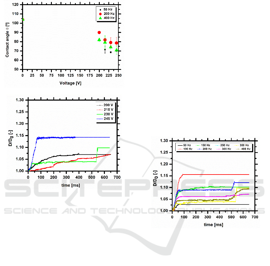
Figure 1 shows the contact angle obtained under
electrostatic actuation, as a function of the applied
electric potential, for different imposed frequencies
and the temporal evolution of the spreading contact
diameter of a droplet on two coplanar electrodes,
with w=1400 μm, for 350 Hz, with different values
of the applied electric potential. Consistently with
the Young-Lippmann equation, the contact angle
decreases with the increment of applied tension and,
consequently, the spreading droplet diameter is
larger for increasing imposed voltages for the same
frequency, being this trend observed, regardless of
the configuration set-up.
The trend observed for the contact angles is in
line with the results expected, at the light of Young-
Lippmann equation and evidences the independence
of the contact angles with the imposed frequency.
This indicates that the spreading diameter is
independent from the imposed frequency which can
be lowered, to simplify the chip arrangement and
programming.
Figure 2 emphasizes that the droplet motion is
irreversible due to the high adhesion force of the
PDMS substrate. Hence after the spreading of the
droplet, up to its maximum diameter, this strong
adhesion due to the high contact angle hysteresis
(larger than 20º, as reported in previous work –
Vieira et al., 2017) promotes energy dissipation at
the contact line, thus restraining the spreading
motion of the droplet. The energy dissipation during
this motion precludes the recoiling, thus turning the
motion of the droplet irreversible. Consequently, it is
difficult for the droplet to be transported to the
subsequent electrodes. The dynamic behaviour of
the droplet illustrated here for 230 V, is consistently
observed for all the applied voltages, in steps of 15
V between 200 and 245 V.
Design, Test and Fabrication of a Droplet based Microfluidic Device for Clinical Diagnostics
91
(a)
/(b)
Figure 1: (a) Contact angle as a function of the applied
electric potential for different imposed frequencies and (b)
evolution of the spreading diameter for 350 Hz of a GFP
droplet, for the configuration 2a=60 μm and w=1400 μm.
The dielectric substrate is PDMS. The volume of the
liquid droplet is 1.8L.
In a more quantitative approach, the spreading
velocity and the maximum diameter of the droplet,
as a function of the imposed frequency are shown in
figure 2, for the different voltages. The current
configuration requires very high imposed voltages
(above 200 V), being limited to 245 V, as above this
value, the dielectric breakdown occurs leading to
electrolysis inside the droplet, which in turn
generates a violent droplet disintegration, in
agreement with the observations reported, for
instance by Mugele and Baret (2005) and by Cooney
et al. (2006). The difference between the green (230
V) and the blue (245 V) lines is small, which may be
indicative of contact angle saturation. On the other
hand, the minimum voltage required to observe any
droplet response to the actuation on the chips is 200
V.
Analysis of figures 2 and 3 suggests that droplet
dynamics is nearly independent from the imposed
frequency. However, the results suggest that the
droplet has a weaker response to low frequencies (50
Hz) and a swifter response for frequencies between
100-300 Hz, although one cannot identify any
monotonic trend between the frequency and the
spreading diameter or the velocity. On the other
hand, maximum spreading diameters are observed
for the highest imposed frequency (400 Hz), but the
droplet depicts a lower response in time. This trend
is attributed to the imposed electric force that must
overcome the resistance to droplet motion associated
to the energy dissipation on the surface. The
velocities obtained here are lower than those
reported in other studies in the literature (e.g.
Cooney et al. 2006, Fan et al. 2007, Sen and Kim,
2009), as the chips configuration is not optimized
yet. Also, most of the fluids used in the
aforementioned studies are salt solutions and not
biofluids.
Figure 2: Temporal evolution of the spreading diameter of
a GFP droplet on a PDMS substrate, actuated at 230 V for
different imposed frequencies, for the configuration
2a=60 μm and w=1400 μm. The volume of the liquid
droplet is 1.8L.
To infer on the influence of the electrodes width
on the dynamic response of the droplets, four
alternative electrode configurations were tested.
Comparative results between the different
configurations are presented in figure 4, which
depicts the contact line velocity and the maximum
spreading diameter, as a function of the imposed
frequency. The results highlight that the
configuration with w=120 μm provides the worst
droplet response to the electrostatic actuation,
expressed by the low values of the spreading
velocity and of the non-dimensional spreading
diameter D/D
0
. The response of the droplet under
actuation on all the other configurations is very
similar, being however, overall more regular for the
BIODEVICES 2018 - 11th International Conference on Biomedical Electronics and Devices
92
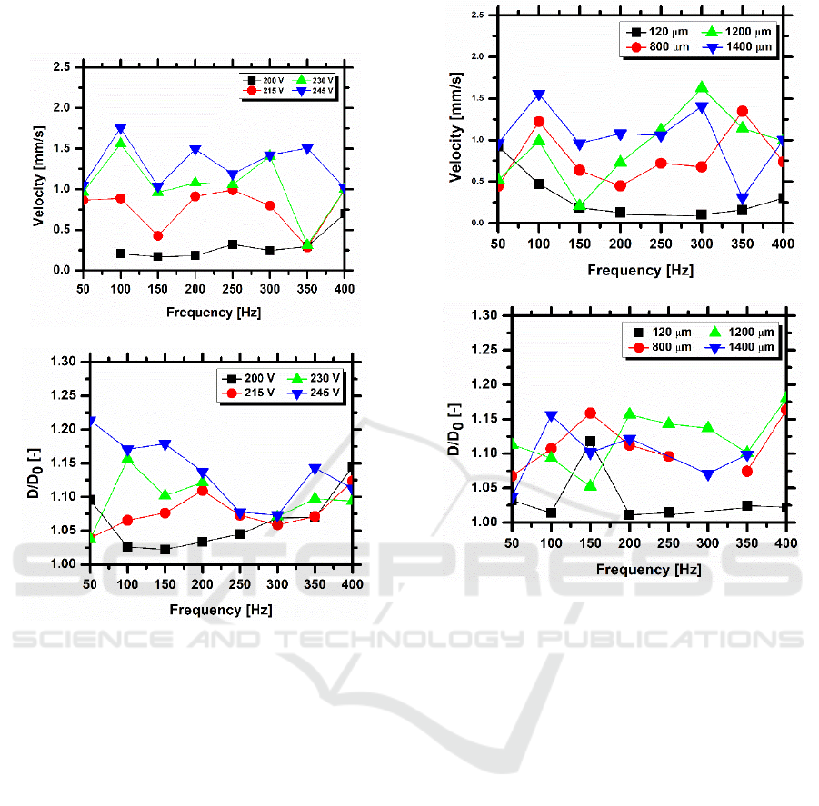
chip with w =1200μm, mainly regarding the values
achieved for the maximum diameter.
(a)
(b)
Figure 3: (a) Spreading velocity of the contact line and (b)
maximum spreading dimensionless diameter of a GFP
droplet on PDMS, moving between coplanar electrodes for
the configuration 2a=60 μm and w=1400 μm for different
applied voltages and an imposed frequency. The volume
of the liquid droplet is 1.8L.
In agreement with figures 1 and 2, the set of
plots shown here does not identify a monotonic
trend between the spreading velocity and diameter
and the imposed frequency. Overall it mainly
indicates a slower response for very low frequencies
(50Hz) and faster response (with larger spreading
diameters) for higher imposed frequencies.
Nevertheless these plots show that regardless of the
imposed frequencies, the configurations with w
=120m and w =1400m provide a better dynamic
response which enables droplet motion.
(a)
(b)
Figure 4: (a) Spreading velocity and (b) maximum
spreading dimensionless diameter of a GFP droplet on
PDMS, moving between coplanar electrodes for the
different configurations, for an imposed frequency of
350Hz and an imposed electric potential of 230 V. The
volume of the liquid droplet is 1.8L.
For all the configurations tested and discussed in
the previous paragraphs, the dielectric material used
was PDMS, with a thickness of 30m. This
thickness was set following the values reported in
the literature and due to some limitations of the
microfabrication method, which did not allow a
deposition of a thinner dielectric layer. Vieira et al.
(2017), further showed improvements in the
transport efficiency of the droplet by coating the
PDMS with a chemical compound called Glaco®,
which is mainly a perfluoroalkyltrichlorosilane
combined with perfluoropolyether carboxylic acid
and a fluorinated solvent (Kato et al., 2008).
Glaco®, improves the dynamic response of the
droplet, turning the dielectric surface
superhydrophobic (depicting equilibrium contact
angles
e
=153±2º, with a hysteresis lower than 10º,
as measured by Vieira et al. 2017) and reducing the
Design, Test and Fabrication of a Droplet based Microfluidic Device for Clinical Diagnostics
93
adsorption of the biocomponents by the PDMS,
which was shown to improve the local wettability at
droplet-dielectric surface interaction. However,
Vieira et al. (2017) also show that the Glaco®
coating increases substantially the thickness of the
dielectric layer, turning difficult for the droplet to
respond to the electrical actuation, according to
Young-Lippmann equation. Consequently, despite
functional, the chips are working under very high
imposed voltages and frequencies. Hence, to scale
down the transport section, addressing smaller
dimensions and thinner dielectric layers, a model
was developed and simulations were performed
using COMSOL Multiphysics 4.3b, as described in
Section 2.2. It is worth reminding that the boundary
conditions addressing the wettability of the dielectric
surface were set to match the set PDMS+Glaco (
e
=
153º) and the biofluid droplet has the properties
depicted in Table 1 for GFP (1.71x10
-3
m). The
thickness of the film was reduced to 10m,
following the recommendations of Di Virgilio
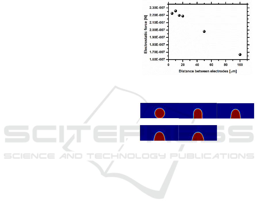
(2015) and of Mata et al. (2016). The first important
output taken from the simulation performed was the
electric force generated by the electric field, for
different distances between electrodes 2a. The
results, depicted in figure 5 show that the distance
2a considered in the experimental approach was
over dimensioned and that the optimum distance
which maximizes the electric force generated is
around 10m. The values obtained for the electric
force are in qualitative agreement with those
reported by Di Virgilio (2015), with a similar
geometry. Performing the entire simulation of the
dynamic behaviour of the droplet for the optimum
distance between electrodes 2a = 10m, as depicted
in figure 6, the droplets shows a significant motion
for an applied voltage of 70V, which is significantly
lower than the 200V required in the first tested set of
chips. Also, the imposed frequency could be lowered
down to 9Hz, matching the very low values achieved
by Fan et al. (2007). Overall the dynamic behaviour
of the droplet is in qualitative agreement with that
reported in the simulations of Di Virgilio (2015).
The nearly independent dynamic response of the
droplet with the imposed frequency, shown in the
experimental tests is well patent in the simulation
and in the results of Di Virgilio (2015): droplet
motion is not affected even at frequencies lower than
the 50Hz experimentally tested.
Despite preliminary, these results are quite
promising, considering that other parameters such as
the thickness of the dielectric layer can be further
optimized. The new patch of chips being currently
produced are following a fabrication method
allowing a more precise control of the thickness of
the dielectric layer, so that it can be quite reduced
now. This new patch of chips will now be tested
following a procedure similar to that reported here to
then be integrated in the more complex design of the
entire microdevice, towards the assembly of the final
prototype.
Figure 5: Electric force generated by the electrodes
configuration, as a function of the distance between
electrodes.
t = 0ms t = 0.75ms t = 1.50ms
t = 2.25ms t = 3ms
Figure 6: Sequence of images showing the motion of the
GFP droplet on co-planar electrodes, spaced with a
distance 2a = 10m, for an imposed electric potential of
70V and an imposed frequency of 9Hz. The volume of the
liquid droplet is 1.8L.
4 CONCLUSIONS
The present paper describes the design,
microfabrication and test of an electrowetting chip to
transport and manipulate biosamples, towards the
development of a microfluidic device for clinical
diagnostics, based on cell elasto-mechanical
properties and on the rheology of the biofluidic
droplets. Emphasis is put here in the design of the
section for sample manipulation and transport.
Experiments are performed, at an earlier stage of the
work, to determine basic chip dimensions and
configuration (size and positioning of the
electrodes), allowing its best performance, evaluated
based on droplet dynamics (spreading/receding
diameter and contact line velocity). Then, to scale
down this section, for its proper integration in the
BIODEVICES 2018 - 11th International Conference on Biomedical Electronics and Devices
94

device, these basic dimensions serve as input for a
numerical model, used to optimize the distance
between the electrodes, the thickness of the
dielectric and the electric potential and frequency to
be applied.
Preliminary results are promising, predicting the
satisfactory behaviour of a chip where the distance
between electrodes could be optimized to 10m, for
a dielectric thickness of 10m. Under these
conditions, the chip can transport droplets of the
order of 0.65mm diameter (thus allowing the
manipulation of biological flows containing cells)
for imposed voltages up to 70V and imposed
frequencies as low as 9Hz. These values are
significantly lower than those achieved in the
preliminary design stages, which could reach
imposed voltages of the order of 230V.
ACKNOWLEDGEMENTS
The authors are grateful to Fundação para a Ciência
e a Tecnologia (FCT) for partially financing this
research through the project UID/EEA/50009/2013,
and for supporting F. Jacinto with a fellowship.
A.S. Moita also acknowledges the contribution
of FCT for financing her contract through the IF
2015 recruitment program and for partially financing
this research through the exploratory project
associated to this contract.
Finally, the authors acknowledge the
contribution of Prof. Susana Freitas and her team
from INESC-MN for the microfabrication of the test
chips.
REFERENCES
Chen, J. Z., Darhuber, A. A., Troian, S. M., Wagner, S.,
2004. Capacitive sensing of droplets for microfluidic
devices based on thermocapillary actuation, Lab-on-a-
Chip, 4(5):473–480.
Cooney, C. G., Chen, C. Y., Emerling, M. R., Nadim, A.,
Sterling, J. D., 2006. Electrowetting droplet
microfluidics on a single planar surface. Microfluidics
and Nanofluidics, 2(5):435–446.
Dance, A., 2017. The making of a medical microchip.
Nature, 545:512-514.
Di Virgilio, V., 2015. Contactless electrowetting, PhD
Thesis, Universitat Politècnica de Catalunya,
Catalunya, Spain, 2015.
Fan, S.-K., Yang, H., Wang, T.-T., & Hsu, W., 2007.
Asymmetric electrowetting--moving droplets by a
square wave. Lab-on-a-Chip, 7(10):1330–1335.
Geng, Hongyao., Feng, J., Stabryl, L. M., Cho, S. K., 2017
Dielectroetting manipulation for digital microfluidics:
creating, transporting, splitting, and merging droplets.
Lab-on-Chip, 17:1060-1068.
Gosset, G.R., Tse, H.T.K., Lee, S.A., Ying, Y., Lidgren,
A.G., Yang, O.O., Rao, J., Clark, A.T., Di Carlo, D.,
2010. Hydrodynamic stretching of single cells for
large population mechanical phenotyping, PNAS,
109(20):7630-7635.
Kato M, Tanaka A, Sasagawa M, Adachi H, 2008.
Durable automotive windshield coating and the use
thereof. US Patent, 8043421 B2.
Li, Y., Fu, Y. Q., Brodie, S. D., Alghane, M., Walton, A.
J., 2012. Integrated microfluidics system using surface
acoustic wave and electrowetting on dielectrics
technology. Biomicrofluidics, 6:012812.
Manz, A., Widmers, H. M., Graber, N., 1990.
Miniaturized total chemical analysis systems: A novel
concept for chemical sensing, Sensors and Actuators
B: Chemical, 1(1-6):244–248.
Mata F., Moita, A.S., Kumar, R., Cardoso, S., Prazeres
D.M.F, Moreira, A.L.N., 2016. Effect of surface
wettability on the spreading and displacement of
biofluid drops in electrowetting. Proceedings of ILASS
– Europe 2016, 27th Annual Conference on Liquid
Atomization and Spray Systems, Sep. 2016, Brighton,
UK 4-7 September 2016. ISBN 978-1-910172-09-4.
Moita, A. S., Laurência, C., Ramos, J.A., Prazeres, D. M.
F., Moreira, A. L. N., 2016. Dynamics of droplets of
biological fluids on smooth superhydrophobic surfaces
under electrostatic actuation, J. Bionic Eng., 13:220-
234.
Mugele F, Baret J C., 2005. Electrowetting: From basics
to applications. Journal of Physics Condensed Matter,
17:R705–R774.
Sen, P., Kim, C.-J. C., 2009. Capillary spreading dynamics
of electrowetted sessile droplets in air. Langmuir,
25(8):4302–4305.
Vieira, D. Mata, F., Moita, A.S., Moreira, A.L.N., 2017.
Microfluidic Prototype of a Lab-on-Chip Device for
Lung Cancer Diagnostics. Proceedings of the 10th
International Joint Conference on Biomedical
Engineering Systems and Technologies - Volume 1:
BIODEVICES, 63-68, 2017, Porto, Portugal, 21-13
February 2017. DOI: 10.5220/0006252700630068,
ISBN: 978-989-758-216-5.
Wheeler A R, Moon H, Kim C J, Loo J A, Garrell R L.,
2004. Electrowetting-based microfluidics for analysis
of peptides and proteins by matrix-assisted laser
desorption/ionization mass spectrometry, Analytical
Chemistry, 76:4833–4838.
Wyatt, C. N., Kim, C.-J., 2012. Droplet actuation by
Electrowetting-on-Dielectric (EWOD): A review. J.
Adhesion Sci. Tech., 26:1747-1771.
Yoon, J Y, Garrell R L., 2003. Preventing biomolecular
adsorption in electrowetting-based biofluidic chips,
Analytical Chemistry, 75:5097–5102.
Design, Test and Fabrication of a Droplet based Microfluidic Device for Clinical Diagnostics
95
