
FDTD Modeling and Simulation of Organic Light Emitting Diode
with Improved Extraction Efficiency using Moth-eye Anti Reflective
Coatings
B. M. Chaya, M. Venkatesha, Shruthi Neduri and K. Narayan
Department of Electronics and Communication Engineering, Sai Vidya Institute of Technology,
Rajanukunte, Bangalore, India
Keywords: Organic Light Emitting Diode, Anti Reflective Coatings, Light Extraction Efficiency.
Abstract: In this work modeling of two dimensional fluorescence based bottom emitting Organic Light Emitting
Diode (OLED) using Moth eye Anti Reflective Coatings (ARC) is presented. The Finite Difference Time
Domain (FDTD) mathematical modeling has been used to analyze the light extraction efficiency from
fluorescence based Organic Light Emitting Diode (OLED). The OLED structure has been simulated by
using 2D Moth-eye Anti Reflective coatings. The Finite Difference Time Domain (FDTD) method is used
to model and simulate the OLED structure. An enhancement of Light Extraction Efficiency (LEE) has been
achieved by inserting Moth-eye Anti Reflective coatings on the surface of the glass substrate which reduces
reflection and increases the transmission. Comparative study is carried out between hexagonal photonic
crystals and Moth eye Anti reflective coatings by placing these nanostructures on the substrate of OLED.
The improvement in the far field intensity of OLED structure is achieved by optimizing the angular
distribution of light through the substrate with moth eye anti reflective coatings.
1 INTRODUCTION
Organic Light Emitting Diode (OLED) is an
luminescence based device which is formed using
organic layers to produce light emission. The
excitons excitation is achieved by driving voltage as
dc source below 10 Volts (Tang and VanSlyke,
1987). The radiative decay of exciton is achieved
due to singlet, Hence the name Fluorescence based
OLED. In the OLED stack the device efficiency is
achieved by varying the electron transport layer. In
order to improve the extraction efficiency, various
transport layers are used with different work
functions as in (Do et al., 2003).
In order to various losses that exist in OLED,
many experiments were conducted in the literature.
In order increase the device performance the
Photonic Crystals (PC) is placed upon glass
substrate to realize low power consumption using
Nano imprint lithography technique which showed
better performance than conventional OLEDs (Lee
et al., 2003).
The Silicon Nitride (SiN) Photonic Crystals (PC)
are used to control light which is acting as a
dielectric medium to extract maximum amount of
photons which is trapped in high index guided
structures. Various approaches have been reported in
the literature to improve efficiency and extract
modes outside the OLED.
However different experiments on Organic LEDs
are carried out to address substrate losses using
different structures of the Photonic crystals and
using different substrates as reported in (Kim et al.,
2004). The light extraction efficiency has been
achieved by incorporating dielectric Nano particles
placed at the substrate and scattering efficiency is
calculated by using Mie theory as discussed in
(Mann et. al., 2017).
The Anti reflective coatings can be used on the
backside of the glass substrate to achieve
enhancement in the luminescence and was fabricated
by Magnesium Fluoride (Saxena et al., 2008) In the
recent advancements the Moth eye Antireflective
coatings were introduced to used it for display
applications, such as solar cells (Tan et al., 2017).
The light out coupling efficiency is enhanced by
using Bio inspiring concept of moth eye anti
reflective coatings. This is used to suppress
266
Chaya, B., Venkatesha, M., Neduri, S. and Narayan, K.
FDTD Modeling and Simulation of Organic Light Emitting Diode with Improved Extraction Efficiency using Moth-eye Anti Reflective Coatings.
DOI: 10.5220/0006651702660272
In Proceedings of the 6th International Conference on Photonics, Optics and Laser Technology (PHOTOPTICS 2018), pages 266-272
ISBN: 978-989-758-286-8
Copyright © 2018 by SCITEPRESS – Science and Technology Publications, Lda. All rights reserved
reflection and extract maximum modes outside the
OLED compared to Conventional approaches of
OLED. (Zhou et al., 2014).
This research work is being carried out aiming at
increasing the light extraction efficiency of OLED.
In this paper an OLED with moth eye Anti reflective
coatings are used with glass as a substrate and by
using point dipole source to increase the number of
photons in the emissive layer. In this work, we are
addressing substrate losses that exist when light is
coupling out into the air. This is done by
incorporating moth eye Anti reflective coatings
between air medium and the substrate. Comparative
study is carried out for different structures of OLED.
2 OLED STRUCTURE
2.1 Design of OLED
Figure 1, shows the structure of Organic Light
Emitting Diode (OLED) which is modeled using
Lumerical FDTD (Finite Difference Time Domain).
The proposed structure uses glass substrate. The
device structure consists of thin active organic layers
integrated into injected electrons and holes. These
transport and organic Layers which is about 200nm
is placed between anode and cathode layer. In this
structure, the Moth eye Anti reflective coatings are
placed between air medium and the Glass substrate.
This OLED designed is proposed in this paper to
achieve maximum light out coupling from the
fluorescence based green light emitting device. The
green light is due to the organic layers present in the
device which is aiming to emit light at green
wavelength at 540nm.
Air
Moth Eye Reflective Coatings,
Pitch=300nm, Radius of
curvature=100nm
Glass Substrate
Anode ITO =120nm
HIL=CuPc=15 to 30nm
HTL=TPD=40nm
α-NDP =30nm
Alq3=60nm
HBL=BCP=30nm
Cathode=Al=100nm
Figure 1: Fluorescence based OLED.
2.2 Modeling of Moth Eye Anti
Reflective Coatings
The Moth eye Anti Reflective coatings very
important in various display applications like LEDs,
photo detectors and solar cells, where reflection loss
is to be minimized. This structure is inspired by Bio
mimic array and reduces the internal reflectance
outside their operating wavelength(Cho et al., 2017).
The eye of a Moth insect has a periodic
nanostructure in coating layer are tapered and air
fraction decreases in the coating towards the
substrate
We set x span and y span to be 0.5um for the
simulation region, which includes only one unit cell.
Since the structure exhibits both symmetry and
periodicity.
The boundary condition chosen is as follows:
•x-min bc = x-max bc = antisymmetric
•y-min bc = y-max = symmetric
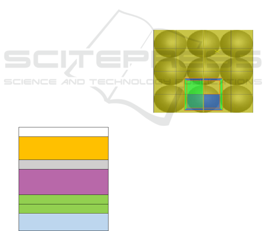
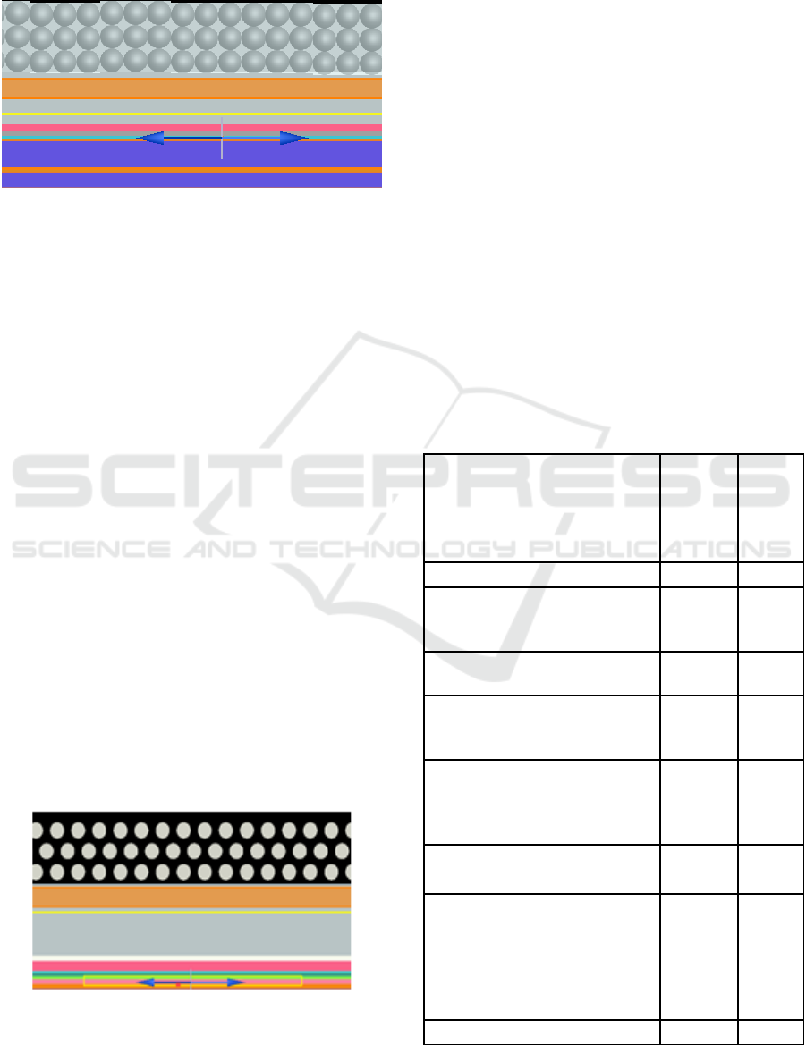
Figure 2: Modeling of Moth-eye anti reflective coatings
(ARC) with pitch chosen to be 300nm and radius of
curvature of 100nm.
In this simulation, the reflectance with respect to
wavelength is measured and get insight of where
Electromagnetic energy is absorbed and where
photoelectrons are created. FDTD simulation
method is used to model this Moth-eye gold
nanostructure.
2.3 Modeling of OLED using Moth Eye
Anti Reflective Coatings
The OLED device structure is modeled and
simulated as shown in the Figure 3 using various
materials as shown in Table 1. The modeling is done
by using Lumerical FDTD (Finite Difference Time
Domain). The device structure consists of thin active
FDTD Modeling and Simulation of Organic Light Emitting Diode with Improved Extraction Efficiency using Moth-eye Anti Reflective
Coatings
267
organic layers which are integrated with moth-eye
anti reflective coatings using Silicon Nitride material
and glass substrate.
Figure 3: Modeling of OLED using Moth eye Reflectors
(XY View).
The thickness of organic layers is about 200nm
and is positioned between anode and cathode. The
Moth-eye Anti reflective coatings are made of
silicon Nitride material is of around 400 nm
thickness. The total stacking height of OLED
structure is of the order of 1500 nm.
The modelling is done for the proposed structure
shown in Figure 1. The moth-eye Anti-reflectors
coatings are used to reduce the internal reflectance
on the surface of the substrate.
These coatings are used upon the surfaces to
improve the out coupling efficiency of the devices.
The Moth-eye Antireflective coatings nanostructures
increase the efficiency of Organic Light Emitting
Diode .This structure is inspired by Bio mimic array
and operating at 540nm and reduces the internal
reflectance outside their operating wavelength.
2.4 Modelling of OLED using Two
Dimensional Hexagonal Photonic
Crystals
Figure 4, shows the modelled Photonic Crystal (PC),
used in OLED.
The photonic crystal is used for modeling for
different OLED structures as discussed in
Figure 4: Modeling of OLED using Hexagonal Photonic
Crystal (XY View).
literature work. The PC used in this work has lattice
constant of 300nm and radius is of 100nm. The
simulation is done using Photonic crystal made up of
Silicon Nitride which has refractive index of 1.9.The
Brillouin zone chosen is in the form of a hexagon.
Hence it is called as Hexagonal Lattice Brillion
Zone (Joannopoulos et al.,2008).
This modelling is done using lumerical FDTD
for the design shown in Figure 1 using materials
shown in Table 1. This is simulated using Photonic
crystals to make the comparative study with the
OLED structure with Moth eye Anti reflective
coatings placed on the surface of the glass substrate.
3 OLED MATERIALS
The various materials used in OLED structure are
shown in the Table 1.
The work function for various materials used in
OLED are carefully chosen depending on the energy
levels at metal organic interface abiding by Mott
Schottky limit (Novotny et al., 2006).
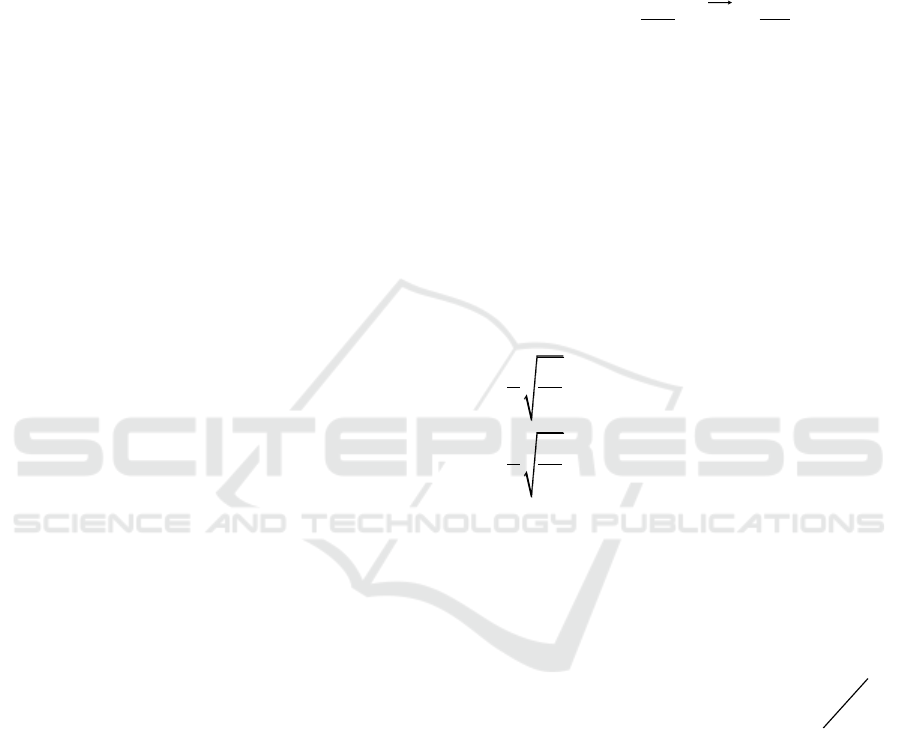
Table 1: Materials used in the OLED Structure.
Materials
Work
Function
Refra-
ctive
index
(n)
Anode –ITO- Indium Tin Oxide
4.7eV
1.806
Cathode- Al- Aluminium
4.1eV
1.031
Hole Blocking Layer (HBL)-
BCP-(2, 9 Dimethyl-4, 7-
diphenyl-1, 10 phenanthroline
3.2eV
1.686
Hole Injection layer(HIL)-CuPC-
(Copper (II) phthalocyanine)
3.1eV
0.47
Hole Transport layer(HTL)-TPD-
(N, N’-Bis (3-methylphenyl)-N,
N’-diphenylbenzidine)
2.6eV
1.67
Alq
3
-Tris(8-
hydroxyquinoline)aluminum
HOMO-
5.62eV
LUMO-
2.85eV
1.68
α-NDP- N,N`- diphenyl-
benzidine
2.5eV
1.82
Photonic crystals–SiN-Silicon
Nitride-(Lattice Constant
=350nm)
Moth Eye Anti Reflective
coatings
(pitch=300nm, radius=100nm)
----
1.9
Glass Substrate
----
1.53
PHOTOPTICS 2018 - 6th International Conference on Photonics, Optics and Laser Technology
268
The thickness variations and Organic Layers
with the HOMO (Highest Occupied Molecular
Orbital) and LUMO (Lowest Unoccupied Molecular
Orbital) levels of organic molecules are given. The
most commonly used HIL is CuPC (Copper (II)
phthalocyanine) is used to improve the carrier
injection efficiency. The HTL used here is
TPD (N, N’-Bis (3-methylphenyl)-N, N’-
diphenylbenzidine).
The hole transport layer and hole injection layer
placed above organic layers. The hole injection layer
is used to improve the carrier injection efficiency,
and serves two purposes, first, it provides a path for
smooth travel of injected holes up to emitting layer.
Second, it functions like electron blocker to confine
electrons within an emitting layer.
4 METHODOLOGY
The Finite Difference Time Domain (FDTD)
method is most widely used method to solve
Maxwell's equations and simulate Nano-photonic
devices(Gedney,2011). FDTD method is used to
investigate and analyze the light propagation. Light
of UV, Visible and IR regions propagating through
different layers with complex geometries can be
analyzed and simulated with the help of FDTD
(Taflove,1995). Thus it is possible to analyze the
propagation of Electromagnetic wave inside the
structure(Sullivan,2013).
Since the OLED device configuration is limited
for single wavelength at 540nm, the optical
thickness of Moth eye is given by(Cho BJ et
al.,2017),
n
2
*d=λ/4 (1)
Where, d= geometrical thickness of the film,λ=
peak wavelength of light emitted by
OLED,n
2
=refractive index of the coating material..
Therefore, d=λ/4*n
2
Where, d= geometrical Thickness of the film, λ=
peak wavelength of light emitted by OLED.
Under these conditions destructive interference
occur and cancel each other and light is coupled out.
For a single homogeneous layer with refractive
index n, will suppress reflectance between
substrate(n
s
) and air (n
a
) for normal incident of light
and optical thickness λ/4, If, n=(n
s
n
a
)
0.5
is fulfilled.
The Far field analysis accounts for the reflection
and refraction that would occur at the Far-field
substrate air interface. The fraction of source power
transmitted into far field is derived.
A point dipole power source is used to generate
charge carriers. The power radiated by an electric
dipole in homogenous material is calculated
(Novonty et al., 2006)
c
pnP
3
||
4
4
2
0
0
(2)
Where,
0
(Cm)=dipole moment and
0
magnetic
permeability,
c
=speed of light.
When the light emerges out of substrate, it would
undergo refraction, reflection at the interface of
substrate and air. This is analyzed by Far Field
analysis.
The mathematical formulation for the electric field
at far field is as shown below:
The Substrate air interface relation is derived by
Fresnel's law(Chutinan et al., 2005),
2
0
2 2 2 2 2
0
22
0
1 . 1 1 1
0
1
| | . sin
2
1
( | | .| | ) sin
2
s s s p
n E d d
n T E T E d d
(3)
Where,
0
= Absolute permittivity,
0
= Absolute
Permeability,
n
1
=Refractive index of air,
n
2
=
Refractive index of Substrate,
s
T
and
P
T
are
calculated as below using Fresnel equations,
2 2 2
1
2
2
| | ( .| | .| | )
s s s p
d
E T E T E
d
(4)
Where,
s
T
and
P
T
are Fresnel transmission power
coefficients in far field,
s
E
and
P
E
are Fresnel
Electric field coefficients in far field.
2
E
= Electric
field beyond the far field interface. The Finite
difference Time Domain (FDTD) method is used
for solving Maxwell’s equations in complex
geometries.
FDTD Modeling and Simulation of Organic Light Emitting Diode with Improved Extraction Efficiency using Moth-eye Anti Reflective
Coatings
269
5 RESULTS
5.1 Far Field Intensity of OLED
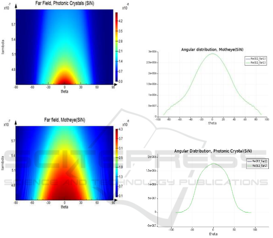
Figure 5(a): Far field Intensity of OLED with Photonic
crystals using SiN Material.
Figure 5(b): Far field Intensity of OLED with Moth eye
Anti Reflective surface with SiN Material.
Figure 5, shows the maximum Light extraction
efficiency from the modeled OLED structure that
escapes into air.
is the angle at which light
emerges out of OLED. This angle is with respect to
the normal to the interface surface. Figure 5(a)
indicate the light emerges out in the range of -30
0
to
+ 30
0
,
when Photonic crystal is placed upon the
substrate. That is range of light emergence is spread
out for near 80
0
.
However the intensity of light is subtended. In
comparison Figure 5(b) shows that light emerges out
with wider range of -50
0
to +50
0
. Also the light
emitted is much more bright when moth eye ARC is
placed upon the substrate.
This indicates that by introducing Moth eye
antireflection coatings on the substrate of OLED, the
emission of light is spread over greater range of
angle and also intensity of light is greater at 540nm.
This is because the Moth eye has a periodic
nanostructure in coating layer are tapered and air
fraction decreases in the coating towards the
substrate, whereas the Photonic crystals has planar
coating layer.
5.2 Angular Distribution of OLED at
540nm
Figure 6(a). Angular Distribution of OLED with Moth eye
Anti Reflective surface with SiN Material.
Figure 6(b). Angular Distribution of OLED with Photonic
crystals with SiN Material.
The Angular distribution outputs are shown for
OLED structures with moth eye and photonic
crystals in figs 6(a) and 6(b).
The output is obtained for the modelling
strucutre shown in figure 3, and the simulation is
done using FDTD method.
It is observed that, the far field intensity for
OLED with moth eye structure is 3 µV/m and that of
OLED with PC is 1.8µV/m. Both the OLED
structures are simulated for Silicon Nitride material.
Hence there is an significant improvement in the
far field intensity in extracting light out coupling
efficiency from an OLED.
PHOTOPTICS 2018 - 6th International Conference on Photonics, Optics and Laser Technology
270
However the presence of Moth-eye structure has
channelized more light through the same angle of
emission which otherwise would have been lost due
to TIR within OLED and reducing internal
reflection.
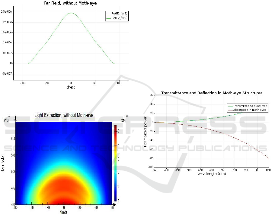
5.3 Simulation Outputs for OLED
Structure without Moth Eye ARC
Figure 7(a). Angular Distribution for OLED without Moth
eye ARC.
Figure 7(b). Far field Intensity for OLED without Moth
eye ARC.
The simulation was carried out for the OLED
structure without using Moth eye Structure on the
surface of the glass substrate. This OLED structure
has no Nano structure placed on the surface of the
glass substrate. The far field intensity is observed to
be 2.5µV/m as shown in the Figure 7(a) and 7(b).
Hence we observe that, by placing Moth eye ARC
better light coupling is achieved.
5.4 Moth Eye Anti Reflective Coatings
Transmission and Reflectance
Curves
The Moth eye Anti Reflective coatings are used to
increase the transmission and to suppress the
reflection that occur while light is out coupling from
the glass substrate and outside OLED.
Figure 8 shows the amount of light transmitted
from the substrate. This simulation output is
obtained for the modelling of moth eye structure as
shown in Figure 2.
In fact such a light source can be monolithically
integrated with Lab-on-a-Chip sensor systems.
Fabrication of such an OLED structures can find
future applications used as a integrated light source
for optical Lab-on-a-Chip based bio-sensors.
Hence, there is a improved light extraction
efficiency for the structure with Moth eye ARC on
the substrate compared to the OLED structure with
Photonic crystals
Figure 8. Transmittance and Reflectance curves.
Figure 8 shows amount of light absorbed by the
moth eye ARC i.e., anything that transmits light is
all absorbed in the substrate. The moth eye ARC are
used because of its periodic nanostructure and are
tapered.
The optimized output for different OLED
structures with different materials are simulated and
the far field intensity values for the same is tabulated
at a wavelength of 540nm as shown in Table 2.
FDTD Modeling and Simulation of Organic Light Emitting Diode with Improved Extraction Efficiency using Moth-eye Anti Reflective
Coatings
271
Table 2: Optimized output obtained for different OLED
structures and different materials.
Parameters
Materials
Far field
intensity
achieved
OLED with
Moth eye Anti
Reflective
coatings
Gold(Au)
3.5 µV/m
Silicon
Nitride(SiN)
2.9 µV/m
Al
2
O
3
3.2 µV/m
OLED with
Photonic
crystals placed
on substrate
Gold(Au)
1.3 µV/m
Silicon
Nitride(SiN)
1.75 µV/m
Al
2
O
3
1.33 µV/m
OLED
structure
without any
Nano structure
-----
2.5 µV/m
6 CONCLUSIONS
In this work, two dimensional Finite Difference
Time Domain (FDTD) modeling of Fluorescence
based OLED using glass substrate has been
presented. An enhanced far field intensity of 3.5µ
Vm
-1
has been achieved for a wavelength of 540 nm
by placing Moth eye Anti reflective coatings
between the substrate and the air medium. The moth
eye Antireflective coatings are placed on the surface
of the substrate of OLED will enable maximum light
out coupling efficiency compared to Conventional
OLED structure. This Anti reflective coatings
reduces reflection and increases transmission of
light.
In this work, Different OLED structures have
been designed with different materials. It is found
that OLED with Moth eye Anti Reflective coatings
with gold nano particles has increased far field
intensity compared to other materials.
ACKNOWLEDGEMENT
The authors would like to thank Science and
Engineering Research Board, Department of Science
and Technology (DST-SERB) Government of India
for funding this research work. File No.
YSS/2015/000382
REFERENCES
Tang, C. and VanSlyke, S. 1987. Organic electrolumines-
cent diodes. Applied Physics Letters, 51 (12), p.913.
Do, Y., Kim, Y., Song, Y., Cho, C., Jeon, H., Lee, Y.,
Kim, S. and Lee, Y. 2003. Enhanced light Extraction
from Organic Light Emitting
Diodes with 2D
SiO
2
/SiN
x
Photonic
Crystals. Advanced Materials, 15
(14), pp. 1214-1218.
Lee, Y., Kim, S., Huh, J., Kim, G., Lee, Y., Cho, S., Kim,
Y. and Do, Y. 2003. A high-extraction- efficiency
Nano patterned organic light-emitting diode, Applied
Physics Letters, 82(21), p.3779.
Kim, Y., Song, Y., Y. W., & Lee, Y. H. 2004. Enhanced
light extraction efficiency from organic light emitting
diodes by insertion of a two- dimensional photonic
crystal structure. Journal of Applied Physics. 96(12),
7629.
Mann V., Rastogi V.2017. Dielectric nanoparticle for the
enhancement of OLED light Extraction efficiency.
Journal of Optics Communications. 387, 202-207.
Saxena K, Mehta Singh D, Kumar Rai V, Srivastava R,
Chauhan G, Kamalasanam M N.2008. Journal of
Luminescence.128, 525-530.
Tan G., Lee J H., Lan Y., Wei MK., Peg L H, Chen I-
Chun, Wu S. T., 2017. Optica.4(7),678-683.
Zhou L., Ou Q D.,Chen J D.,Shen S.,Tang J X.,Li Y Q.,
Lee S. T., 2014. Light Manipulation for organic Opto
Electronics using Bio-inspired moth’s eye Nano
Structure. Journal of Scientific Reports.10, DOI:
10.1038/srep04040.
Joannopoulos, J., Johnson, S., Winn, J. and Meade, R.
2008. Photonic Crystals, Molding The Flow ofLight.
2nd ed. Princeton: Princeton University Press.
Novotny, L. and Hecht, B.2006. Principles of Nano-
Optics, Cambridge, Cambridge University Press.
Chutinan, A. et al., 2005. Theoretical Analysis on light-
extraction efficiency of organic light-emitting diodes
using FDTD and mode- expansion methods, Organic
Electronics. 6(1), pp.3-9.
Gedney S D.2011. Introduction to the Finite-Difference
Time Domain (FDTD) Method for Electromagnetics,
Morgan and Claypool Publishers
Sullivan D M., 2013., Electromagnetic using the FDTD
method, IEEE Wiley Press, 2nd ed., 54.
Taflove A., 1995. Computational Electrodynamics: The
Finite-difference Time-domain Method, Artech House,
Norwood, MA.
Guo K W.2016.Broadband Anti reflection film with Moth
eye like structure for flexible display applications,
JSM Environ Sci Eco ,4(2),1031.
Hedavati M K, Elbahari M., 2016. Anti Reflective
Coatings Conventional Stacking Layers and Ultra Thin
Plasmonic Meta Surfaces.9, 497.
Han Z W, Wang Z, Feng X M, Li B, Mu Z, Zhang J Q,
Niu S C, ren L Q. 2016. Anti Reflective surfaces
inspired from biology: A review. Biosurface and
Biotribology,2,137.
Cho B J, Park J S, Huang J M,Ko J H.2017. Supression of
reflection peaks caused by moth eye type nano
structures for nano structures for anti reflectin
applications studied by using FDTD simulation,
Journal of Information Display.18(3),137-144.
PHOTOPTICS 2018 - 6th International Conference on Photonics, Optics and Laser Technology
272
