Bayesian Multi-sensor Data Fusion for Target Identification
Applications in Naval and Ground based Command and Control Systems
Albert Bodenmüller
Airbus Defence and Space GmbH, D-89077 Ulm, Germany
Keywords: Military Target Identification, Situation Awareness, Bayes Decision Theory, AIS, GMTI.
Abstract: Military Command and Control Systems have to deal with a wide range of different sensors and sources.
Besides traditional information sources like IFF, Tactical Data Links and ESM sensors additional sources
like AIS, Blue Force Tracking and GMTI Radar become important sources for target identification and
classification. A correct identification is an important prerequisite to prevent fratricide and civilian collateral
damages and to complete the Situational Awareness. This paper gives an overview of our solution for the
extension of the Bayesian identification process in order to establish a tactical picture for naval but also for
air and ground targets. For some sensors and important identification source like Automatic Identification
System (AIS), Automatic Target Recognition (ATR) and GMTI Radar our solution approach will be
detailed.
1 INTRODUCTION
In the first section of this paper the current existing
military standard of target identification and
classification will be described. This standard fusion
process uses Bayes decision theory as described by
(Desbois, 2009) and (Stroscher, 2000). It has already
been implemented in airborne reconnaissance
systems and different naval and ground based Air
Defense Systems, but it is not limited to military
systems; it may be used for any identification and
categorization problem.
Future systems will use the principle also for
renegade detection and more granular rating of
various kinds of suspicious behaviour. The
implementation of this standardized fusion process
ensures the comparability of results and the
exchange of source data in future.
Section II will give an overview of the principles
of Bayesian Fusion for target identification and
classification, section III will detail the proposed
processing of some non-standardised sensors and
sources in a Command and Control (C2) system.
The paper describes our approach for some
additional sensors which were not yet considered in
the identification standard. For each of the described
sources the sensor’s provided source information
and the required data for the processing is indicated.
2 PRINCIPLES OF BAYES
FUSION
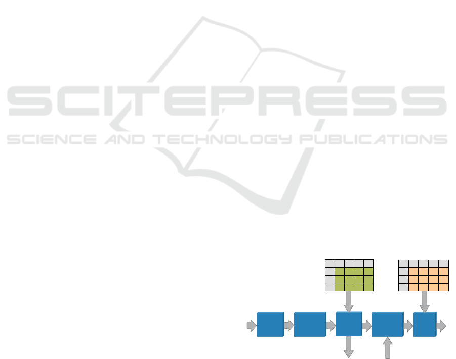
2.1 Source Processing
The identification process consists of two main
processing parts: The first step is a source
processing component, which provides the source
specific processing, which is unique for each source
type (Figure 1), and the second step is the fusion
component, which has the task to combine and fuse
all contributing sources of information and to assign
the final decision for the identification and
classification.
Figure 1: Identification Source Processing.
Following the flow of information the initial step
ID Source
Association
Pre-Conversion
Combining
Conversion
Post-
Conversion
Combining
Sensor Data
Kinematic Data
Track data
Mapping
LV in SDOC
CLV in SDOC
LV in
EBIOC/POC
Declaration
LV in SDOC
to external
IDCP nodes
LV in SDOC
from external
IDCP nodes
Standard
Interface
for IDCP
data exchange
p(D1|O1) p(D1|O2) … p(D1|On)
O
1
O
2
… O
n
D
1
…
D
m
… … … …
p(Dm|O1) p(Dm|O2) … p(Dm|On)
SPM
p(O
1
|B
1
) p(O
1
|B
2
) … p(O
1
|B
n
)
B
1
B
2
… B
n
O
1
…
O
m
… … … …
p(O
m
|B
1
) p(O
m
|B
2
) … p(O
m
|B
n
)
MM
ID Source
Association
Pre-Conversion
Combining
Conversion
Post-
Conversion
Combining
Sensor Data
Kinematic Data
Track data
Mapping
LV in SDOC
CLV in SDOC
LV in
EBIOC/POC
Declaration
LV in SDOC
to external
IDCP nodes
LV in SDOC
from external
IDCP nodes
Standard
Interface
for IDCP
data exchange
p(D1|O1) p(D1|O2) … p(D1|On)
O
1
O
2
… O
n
D
1
…
D
m
… … … …
p(Dm|O1) p(Dm|O2) … p(Dm|On)
SPM
p(D1|O1) p(D1|O2) … p(D1|On)
O
1
O
2
… O
n
D
1
…
D
m
… … … …
p(Dm|O1) p(Dm|O2) … p(Dm|On)
SPM
p(O
1
|B
1
) p(O
1
|B
2
) … p(O
1
|B
n
)
B
1
B
2
… B
n
O
1
…
O
m
… … … …
p(O
m
|B
1
) p(O
m
|B
2
) … p(O
m
|B
n
)
MM
p(O
1
|B
1
) p(O
1
|B
2
) … p(O
1
|B
n
)
B
1
B
2
… B
n
O
1
…
O
m
… … … …
p(O
m
|B
1
) p(O
m
|B
2
) … p(O
m
|B
n
)
MM
Bodenmüller, A.
Bayesian Multi-sensor Data Fusion for Target Identification - Applications in Naval and Ground based Command and Control Systems.
DOI: 10.5220/0006629401070114
In Proceedings of the 7th International Conference on Sensor Networks (SENSORNETS 2018), pages 107-114
ISBN: 978-989-758-284-4
Copyright © 2018 by SCITEPRESS – Science and Technology Publications, Lda. All rights reserved
107

is to establish an unique association between a
sensor or source information and a system track.
When no related existing system track can be found,
a new track based on the kinematic data of the
sensor will be established. This will be performed
for those sensors or sources, which provide
positional and or kinematic data, e.g. a Blue Force
Tracking / Friend Force Information system will
normally provide the actual own position
information. During this process the results of
sensors like Electronic Support Measure (ESM) or
Ground Moving Target Indicator (GMTI) Radar
including the contributing collateral data is assigned
to a track. For many sensors the association process
and the pre-conversion combining are an integrated
process making a final hard decision, if a source
declaration is made or not.
In some cases the periodical association match
analysis is input into a pre-conversion combining
step, which uses a hysteresis or stochastic mean of
several association attempts to make the final
declaration hard decision.
The source processing is specific for each kind of
sensor and such the determined declarations are not
in a form which is appropriate for fusion. Hence
they are converted into a Likelihood Vector (LV),
which is a set of probabilities related to appropriate
types of object classes. The standard proposes for
this conversion the application of a Source
Probability Matrix, which represents the probability
of the source to make these source specific
declarations given a known object type. The Source
Probability Matrix (SPM) contains for each possible
declaration, which can be made by a source, the
related likelihoods. Different qualities or
confidences related to the association process are
considered by different SPMs.
Given a determined source declaration and a
priori determined source probabilities in the SPM
the conversion step is performed by selection of the
related row of the source specific SPM. The result of
the conversion step is a Likelihood Vector (LV) in
the Source Discrimination Object Class (named LV
in SDOC) to which additional collateral information,
which is required for the mapping stage, is attached.
The result of this conversion of a declaration D
i
is a source specific Likelihood Vector LV
i
which
can be written in the following way:
LV
i
= (p(D
i
|O
1
), p(D
i
|O
2
), …, p(D
i
|O
j
))
(1)
where p(D
i
|O
j
) denotes the probability of declaration
D
i
given Object property O
j
.
The LV in SDOC expresses the performance of
that particular source to make this declaration.
There are different possibilities to exchange
identification information between different
identifying and classifying systems or nodes. One
possibility is to exchange final identification and
classification results as this is performed via Tactical
Data Links e.g. Link-16 or Link-22. The
disadvantage is that only the final result is available
such that receiving nodes are not able to assess what
the basis of this assessment had been. So the
comparability of final results is often a problem
when different systems interact in a joint combined
mission. Therefore the exchange of identification
source data is preferred. The exchange of Likelihood
Vectors or references on harmonized pre-defined
LVs enables a standardized identity information
exchange between fusion nodes. By this way the
source information and the confidence of the
information is transferred, but the information has
not yet been interpreted, i.e. the allegiance, the
distinction of civil/military targets or the platform
data has not been derived.
When more than one sensor or source of the
same type (i.e. using the identical SDOC) of either
several own sensors or by receiving data from other
identification nodes contribute to one track, the
combination of these LVs is performed by column
wise multiplication in the Post Conversion
Combination step according the following formula:
(2)
with CLV = (p(D
1,… ,
D
N
|O
1
), …, p(D
1,… ,
D
N
|O
M
)).
The Combined Likelihood Vector (CLV) is
determined by a column multiplication of the single
contributing LVs, and is still in form of the source
specific SDOC. Such a CLV in SDOC contains the
complete information of one source type which
contributes to the final result of the
identification/classification.
2.2 Mapping Processing
A Likelihood Vector or Combined Likelihood
Vector in SDOC is a source specific representation
of information and such different LVs in SDOC
cannot be fused directly without a conversion into a
common format. In the Mapping stage the
LVs/CLVs in SDOC are mapped in such a common
information representation which allows for fusion.
This common information format is called
Output Object Class (OOC). The OOC shall be
defined according the operational needs to
distinguish object categories, e.g. when only a
SENSORNETS 2018 - 7th International Conference on Sensor Networks
108
distinction of civil and military targets is needed, the
OOC may contain only the members:
▪ Military Target;
▪ Civil Target.
When a distinction of basic allegiances is needed the
OOC contains for example the members:
▪ Own Forces (OF);
▪ Enemy Forces (EF);
▪ Non-Aligned (NA).
And a basic distinction of air platform categories can
be defined for example as:
▪ FIGHTER;
▪ BOMBER;
▪ HELICOPTER;
▪ UAV;
▪ AEW AIRCRAFT;
▪ SAR AIRCRAFT;
▪ PATROL AIRCRAFT;
▪ FREIGHT AIRCRAFT;
▪ GLIDER;
▪ BALLOON;
▪ MISSILE;
▪ OTHER AIR TARGET.
Also combinations of basic OOC for certain
applications are reasonable and hence an OOC using
members like friendly fighter, hostile fighter, own
forces civil helicopter etc. may be used. A very
common composite OOC is the Extended Basic
Object Class (EBIOC) using the combinations of
basic allegiances and civil/military targets, e.g. Own
Forces Civil (OFC) and Own Forces Military
(OFM). Depending on the discriminating
capabilities of the contributing sensors/sources and
the user’s operational requirements any kind of
Platform Object Class (POC) can be defined as OOC
for target classification applications. In any case the
OOC members shall be mutually exclusive and the
OOC has to be exhaustive.
The mapping is calculated according the
formula:
1
| | |
M
OOC i j i k MM k j
k
p D B p D O P O B
(3)
where p(D
i
| O
k
) denotes the CLV in SDOC and
P
MM
(O
k
| B
j
) denotes the Mapping Matrix (MM).
The mapping values are stored in a source
specific Mapping Matrix, which is defined
specifically for each corresponding source type and
SDOC. In cases where different operational facts or
constraints have to be considered (e.g. a radar may
be currently jammed) different MMs can consider
such circumstances by different mapping values.
After the mapping stage the LV in OOC is
normalized and then passed to the conflict detection
and fusion process.
2.3 Conflict Recognition on Basis of
Source Information
The next step now is to check if there exist source
inconsistencies and contradictions. The
identification source information after the mapping
step is available in a common normalized format
which enables the recognition of potentially
contradicting information. The
inconsistency/conflict recognition is performed in
the following way:
When an element of a LV in OOC indicates that
one object class is very likely and the same element
of the compared second LV in OOC indicates that
this object class is very unlikely, this test indicates a
possible information inconsistency/conflict.
When an element of a LV in OOC indicates that
one object class is very likely and another element of
the compared second LV in OOC indicates that this
different object class is very likely, this test indicates
a further possible information inconsistency/conflict.
Finally an information content distance measure
between two LVs indicates a possible information
inconsistency when the distance exceeds a certain
threshold:
M
i
ii
yxd
1
(4)
where x and y represent the two LVs to be tested.
This test makes sense particular for large LVs with
many elements. The statistical information distance
between two LVs is a measure for inconsistency.
The inconsistency/conflict recognition tests are
performed for each combination of two contributing
LVs in OOC and the results are summarized for
display purposes to the operational user.
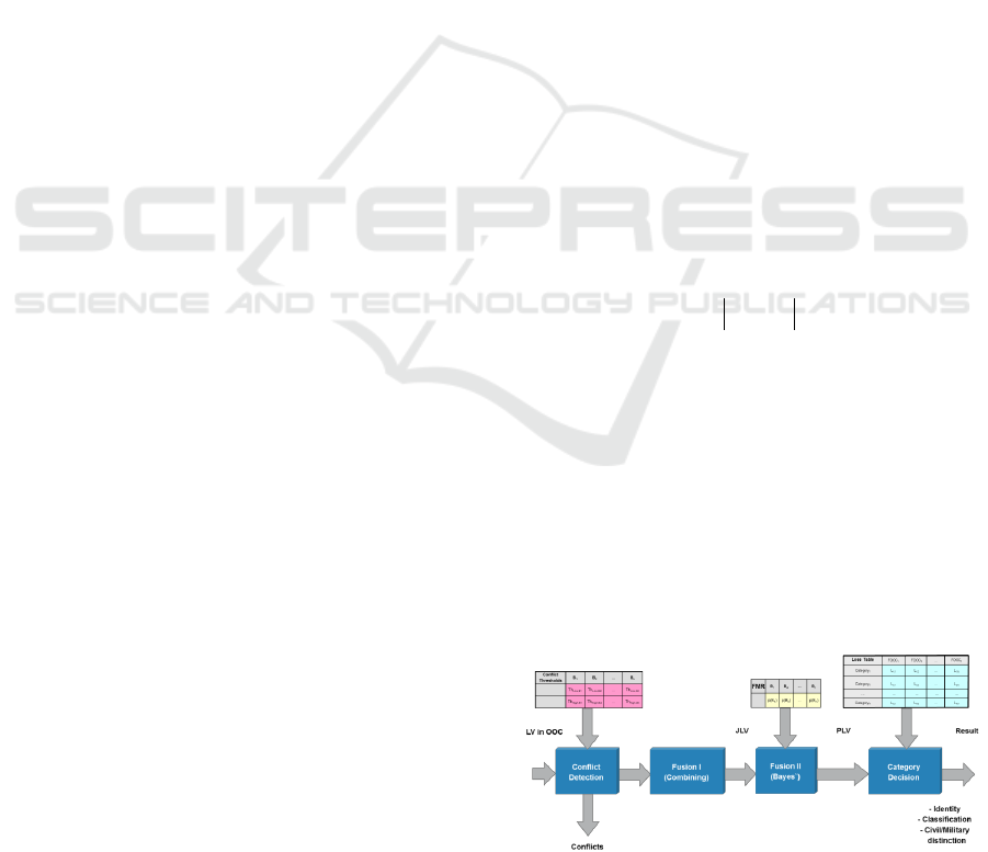
Figure 2 illustrates the following processing
steps including conflict detection, fusion and final
category decision.
Figure 2: Bayesian identification fusion and decision.
Bayesian Multi-sensor Data Fusion for Target Identification - Applications in Naval and Ground based Command and Control Systems
109

2.4 Fusion
In the first step of the fusion process a combination
of all determined contributing LVs/CLVs in OOC is
calculated by a component wise multiplication of all
contributing LVs, building the Joint Likelihood
Vector (JLV). The JLV is a probability distribution
over all members of the OOC. The elements of the
calculated JLV contain the probability that a target
may have these associated declarations given that
the target belongs to that respective OOC:
Mj
j
N
i
iOOC
BDpJLV
,...,1
1
)|(
(5)
In the second step the Posterior Likelihood Vector
(PLV) is calculated from the JLV by application of
Bayes’ Theorem according the following formula:
N
j
jji
jji
ij
BpBDp
BpBDp
DBp
1
|
|
|
(6)
where p(B
j
| D
i
) denotes the PLV, p (D
i
| B
j
) denotes
the JLV and p(B
j
) denotes the required a priori
information called Force Mix Ratio (FMR).
The FMR is a priori information and it quantifies
the relative expectation that a member of that object
class could be found in the area of interest. When
using this processing for target classification
analogously a Platform Mix Ratio is required. The
elements of the calculated PLV contain the posterior
probability that the target belongs to that respective
OOC given the considered declarations.
2.5 Conflict Recognition on Basis of
Combination/Fusion Result
The declaration combination result JLV can be used
additionally to detect possible information
inconsistencies.
When an element of the JLV indicates that one
object class is very likely and the same element of
the a priori FMR indicates that this object class is
very unlikely this test indicates a possible
information inconsistency.
When an element of a JLV indicates that one
object class is very likely and another element of the
a priori FMR indicates that this different object class
is very likely this test indicates a further possible
information inconsistency.
The inconsistency/conflict recognition is
performed on each update of the JLV and the result
is used for display purposes or alerting the
operational user.
2.6 Final Identity Decision Process
The PLV contains the fusion result and such it can
be displayed to operators to support the further
decision process. A final identity decision could be
realized by a simple thresholding function based on
the most likely element. But usually this result is
translated into a recommendation, which regards the
user's needs and operational aspects (Krüger, 2009).
In the domain of target identification the operational
user expects an identity category according to
NATO STANAG 1241 or MIL-STD 6016 and a
civil/military target assessment. In the case of target
classification a platform type or platform specific
type according to military Data Link standards
STANAG 5516 or STANAG 5522 is required.
The decision process is based on a loss function
which uses a set of loss values (see Figure 3), which
define the operational risk when making a wrong
decision.
Figure 3: Identification Loss Table.
The decision process determines for each
decision alternative a specific risk value by
weighting the loss values of that category (decision
alternative) by the posterior probabilities of the
fusion result:
Risk = p(OOC
1
)*L
ID,1
+ p(OOC
2
)*L
ID,2
+ …
+ p(OOC
N
)*L
ID,N
(7)
where p(OOC
n
) represents the n
th
element of the
PLV, L
ID,m
the loss value related to that evaluated
identity (ID) and OOC element m.
The decision alternative comprising the lowest
risk is proposed as final decision result. In those
cases were ambiguous risk values prohibit a decision
based on the risk values a final decision applying a
rule based approach is advised.
If during the identification process additional
operationally important information is attained,
which is not suitable for fusion but relevant for the
L
M,6
L
M,5
L
M,4
L
M,3
L
M,2
L
M,1
KILO
…………………
L
6,3
L
5,3
L
4,3
L
3,3
L
2,3
L
1,3
EFC
L
6,2
L
5,2
L
4,2
L
3,2
L
2,2
L
1,2
OFM
L
6,4
L
5,4
L
4,4
L
3,4
L
2,4
L
1,4
EFM
L
6,6
L
6,5
L
6,1
HOSTILE
L
5,6
L
5,5
L
5,1
SUSPECT
L
4,6
L
4,5
L
4,1
NEUTRAL
L
3,6
L
3,5
L
3,1
FRIEND
L
2,6
L
2,5
L
2,1
ASSUMED FRIEND
L
1,6
L
1,5
L
1,1
UNKNOWN
NAMNACOFCLoss Table
L
M,6
L
M,5
L
M,4
L
M,3
L
M,2
L
M,1
KILO
…………………
L
6,3
L
5,3
L
4,3
L
3,3
L
2,3
L
1,3
EFC
L
6,2
L
5,2
L
4,2
L
3,2
L
2,2
L
1,2
OFM
L
6,4
L
5,4
L
4,4
L
3,4
L
2,4
L
1,4
EFM
L
6,6
L
6,5
L
6,1
HOSTILE
L
5,6
L
5,5
L
5,1
SUSPECT
L
4,6
L
4,5
L
4,1
NEUTRAL
L
3,6
L
3,5
L
3,1
FRIEND
L
2,6
L
2,5
L
2,1
ASSUMED FRIEND
L
1,6
L
1,5
L
1,1
UNKNOWN
NAMNACOFCLoss Table
SENSORNETS 2018 - 7th International Conference on Sensor Networks
110

decision, this information is incorporated in the
decision process. For instance when the operational
alert state changes from peace to tension or a target
violates a self-defence safety zone this has to be
considered for the identity decision. For all these
cases a set of dedicated loss tables has to be
provided, which contain modified loss values
regarding operational facts and target relevant
criteria.
3 NON-STANDARDISED
SOURCE TYPES FOR
IDENTIFICATION AND
CLASSIFICATION
The following section describes our solution for
some additional sources and sensors which were not
yet covered by the identification standard. Hence we
enhanced the standard and introduced capabilities
like Automatic Identification System (AIS),
Automatic Target Recognition (ATR) and Ground
Moving Target Indicator (GMTI) Radar. For some
of these the implemented solution is presented in the
following sections.
3.1 Automatic Identification System
The Automatic Identification System (AIS) is
originally a radio-based collision avoidance system
for ships. AIS has the main requirements to
▪ Support the avoidance of collisions by enabling
an efficient navigation of vessels;
▪ Support the protection of the environment by
providing information about the ship’s cargo;
▪ Actively support Vessel Traffic Systems (VTS)
by providing static, dynamic and voyage data.
Besides that port authorities use AIS to warn ships
about hazards, low tides and shoals that are
commonly found at sea. In open sea AIS-enabled
distress beacons are used to signal and locate men
who have fallen overboard (Balduzzi, 2014).
Several state-of-the-art surveillance satellites are
now equipped with AIS (Høye, 2007), thus the fused
information from dual sensors Radar and AIS
contributes to global maritime surveillance. But also
naval ships like corvettes and frigates are going to
exploit received AIS data for the improvement of the
maritime picture and tactical situation in real-time.
The information extracted from AIS radio broadcast
data includes:
▪ Static ship data: Maritime Mobile Service
Identity (MMSI), i.e. the vessels unique
identification number, International Maritime
Organization (IMO) ship identification number,
radio call sign, name of the vessel, type of ship;
▪ Dynamic ship data: navigation status, position of
the vessel, time of position, course over ground,
speed over ground, true heading, rate of turn;
▪ Further voyage data: current maximum draught
of ship, hazardous cargo, destination, estimated
time of arrival (ETA) at destination.
In a first step the received positional data of a vessel
are used for the association of the AIS data with
existing system tracks, which is part of the source
data association. If no matching system track is
available a new AIS based system track will be
initiated and the track is updated with the AIS
position data.
For the evaluation of AIS data for military target
purposes it is important to recognize that AIS
message content can be spoofed easily, so that the
manipulated result of the data association process or
from the information exploitation may be erroneous.
Besides the intentional manipulation also any kinds
of intentional and unintentional interference of the
AIS signals or the improper setup of AIS devices
may cause problems in the evaluation.
The AIS is a civilian system, hence no primary
military information is transmitted by default. For
military purposes also dedicated variants (NATO
STANAG 4668 WARSHIP - AUTOMATIC
IDENTIFICATION SYSTEM (W-AIS) and NATO
STANAG 4669 - AUTOMATIC
IDENTIFICATION SYSTEM (AIS) ON
WARSHIPS) exists, which are not handled here in
this paper. In order to use the civilian AIS data for
military identification and classification purposes a
further processing is necessary. In the optimal case a
database providing military and intelligence
information is available, such that the received AIS
data can be compared with it and the stored
(military) information can be retrieved to support the
tactical interpretation. The database content provides
information like ship type, specific type, platform
class and platform name, allegiance, civil/military
information and of course data like sensor
equipment, weapon systems and further tactical
intelligence information.
But usually on board of a ship this intelligence
database is not available and such a more pragmatic
solution was additionally necessary. In this case the
broadcasted MMSI number is exploited, because the
MMSI number uniquely identifies a vessel. The
MMSI is not an identity in the military sense, where
a distinction between civil and military objects and
Bayesian Multi-sensor Data Fusion for Target Identification - Applications in Naval and Ground based Command and Control Systems
111

the membership to either a friendly, neutral or
hostile allegiance is required. Thus the Identification
Digit (MID), which is part of the MMSI number, is
extracted from the MMSI. The MID is a 3 digit
number and defines uniquely the country, where the
vessel is registered.
A simple repository then is used to determine the
allegiance of the country. A civilian/military
distinction is determined from a simple MMSI
repository. When this repository information is not
available for a received MMSI, the civilian/military
distinction is derived from the AIS message content
"type of ship".
AIS is handled as a new source type and hence a
new AIS specific SDOC definition and related SPM
and MMs were introduced:
▪ Surface vessel with an operating AIS transponder
is sending data ´x´;
▪ Surface vessel with an operating AIS transponder
is sending data different from ´x´;
▪ Surface vessel is not fitted with a transponder or
the surface vessel is fitted with an AIS
transponder and the transponder is not operating.
The source type AIS provides the following
declarations:
▪ AIS (data) received;
▪ AIS (data) not received.
The related SPM has therefore the following format
as given in Table 1.
Table 1: AIS Source Probability Matrix.
AIS
SPM
AIS SDOC
Fitted and
operating
sending
data x
Fitted and
operating,
sending data
different x
Fitted and NOT
operating
or NOT Fitted
AIS received
A
B
C
AIS not received
1-A
1-B
1-C
Such the related Mapping matrices have the
following format as indicated in Figure 4.
Figure 4: AIS Mapping Matrix.
One problem in the military identification using
AIS data arises from the ability to manipulate the
transmitted AIS data easily. Additional threats arise
from triggering SAR alerts to lure ships into
navigating to hostile, attacker-controlled sea space
or spoofing collisions to possibly bring a ship off
course. Hence a possibility to detect spoofing targets
is required (Katsilieris, 2013).
In our system we implemented a multitude of
consistency checks for the AIS data, were we
compare the received data with repository and
intelligence information for plausibility. When this
check indicates a sufficient discrepancy the operator
is alerted and he has the possibility either to suppress
the generation of a declaration and the usage of the
AIS data or to declare this vessel as a spoofing
target. This knowledge is then used in the mapping
process for the selection of dedicated mapping
values for the spoofing case or in the final identity
decision processing to assign special identity
categories respectively.
3.2 Automatic Target Recognition
For our naval and ground based Command and
Control Systems (C2 Systems) we are using
(different types of) Daylight/Infra-Red cameras with
Automatic Target Recognition (ATR).
ATR has become increasingly important in
modern defense systems, because it permits
precision strikes against certain tactical targets with
reduced risk and increased efficiency (Dudgeon,
1993). ATR helps to minimize collateral damages to
civilian persons and objects (like cars, vessels,
planes and buildings). The main advantage is that
ATR systems connected and fed by sensors can
detect and recognize targets automatically so that the
workload of an operator can be reduced and the
accuracy and efficiency of the complete C2 System
can be improved.
For the detection and recognition of tactical
relevant objects and their more or less coarse
classification different algorithms are known, e.g.:
▪ Pattern recognition;
▪ Detection theory;
▪ Artificial Neural Network;
▪ Model-based target recognition;
▪ Artificial intelligence and model-based methods.
In our system we implemented a combination of
model-based target recognition and Artificial Neural
Network for detection and classification of target
objects. The result of this processing is already in
the form of a probability distribution over the
discriminated object attributes (object classes), so it
can be processed and fused directly in our
identification and classification processing.
1-A
6
-B
6
1-A
5
-B
5
1-A
4
-B
4
1-A
3
-B
3
1-A
2
-B
2
1-A
1
-B
1
Fitted and NOT operating
or NOT Fitted
AIS MM
SDOC EBIOC
OFC OFM EFC EFM NAC NAM
Fitted and operating
sending data x
A
1
A
2
A
3
A
4
A
5
A
6
Fitted and operating,
sending data different x
B
1
B
2
B
3
B
4
B
5
B
6
1-A
6
-B
6
1-A
5
-B
5
1-A
4
-B
4
1-A
3
-B
3
1-A
2
-B
2
1-A
1
-B
1
Fitted and NOT operating
or NOT Fitted
AIS MM
SDOC EBIOC
OFC OFM EFC EFM NAC NAM
Fitted and operating
sending data x
A
1
A
2
A
3
A
4
A
5
A
6
Fitted and operating,
sending data different x
B
1
B
2
B
3
B
4
B
5
B
6
SENSORNETS 2018 - 7th International Conference on Sensor Networks
112
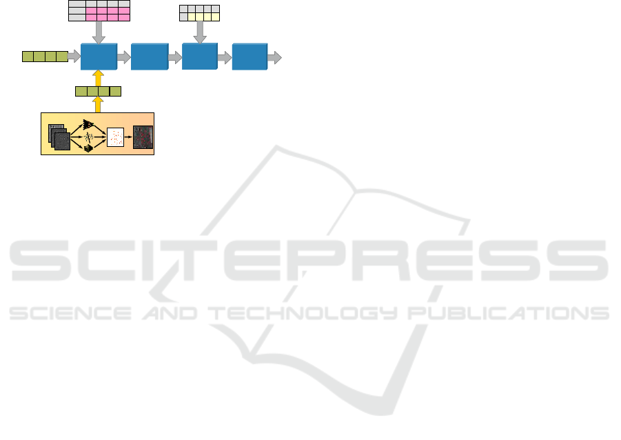
An interface for sensors and sources, which
provide results in a form which is suitable for fusion,
has been introduced and allows for the fusion of the
image processing result, because the ATR result is
already a probability distribution over platform
categories, which correspond to a LV in POC (see
Figure 5). The detection of conflicts with other
sensor results, the combining, Bayes’ processing and
final category decision are performed as described in
section II.
Figure 5: Extension of Bayesian Classification Fusion
with ATR Interface.
3.3 Ground Moving Target Indicator
(GMTI) Radar
Usually GMTI Radars are mounted on
reconnaissance aircrafts and UAV which operate in
high altitudes above the normal height of civil
aircrafts. The observed area has a large extend and
allows for the observation of many ground and
maritime moving targets (Austin, 2010).
The NATO Standard Agreement (NATO
STANAG 4607, 2013) provides a generic and
complex GMTI radar interface standard which
describes the data encoding. Sometimes problems
occur by different interpretation and implementation
of the format description and such a robust interface
connection is necessary (Dästner, 2016).
STANAG 4607 GMTI target reports provide an
enumeration field denoting the classification of the
target. The classification types include e.g. wheeled
vehicles, non-wheeled vehicles, helicopters, fixed-
wing air targets, rotating antenna, maritime etc., for
both live and simulated targets. Additionally an
optional Target Classification Probability (TCP)
may be transmitted.
The classification result set is relative coarsely,
but it is sufficient to perform a target classification
based on it. In order to achieve a good classification
result the interpretation of STANAG 4607 GMTI
target report classification and probability results
shall be clarified with the vendor such that the
GMTI source processing can be optimized for that
sensor and the related mapping values can be
adapted accordingly.
A pre-conversion is not necessary when the
GMTI radar provides the result of the most actual
integrated assessment. Otherwise a temporal
integration using adequate methods like a hysteresis
function or a probabilistic logic using a running
mean p = Σ TCP
i
/n, where TCP
i
is the received
Target Classification Probability, and a threshold
function are used to make a declaration.
The integrated assessment is converted into a
proper related normalized LV in OOC using the
Target Classification Probability for the proper OOC
element, the residual R (R = 1-TCP) is equally
distributed on the remaining OOC components. The
normalized vector is then input into the fusion
process analogously to ATR (Figure 5). In cases
where no TCP is transmitted a proxy LV in OOC is
determined using experience or analytic measures.
4 CONCLUSIONS
In section II a short overview on the principles of
military target identification and classification
applying Bayes reasoning has been given.
In section III this paper addressed some sensors
and source types, which typically contribute to the
Situation Awareness of Combat Management
Systems. The paper presented how data received
from vessel based AIS are evaluated for an enhanced
identification. Also the processing of daylight or
infra-red video streams using ATR algorithms and
processing of GMTI Radar results for target
classification has been presented in this paper.
Due to the military aspects of this paper no
significant simulation or just real results can be
published without disclosure of restricted
information. Nevertheless this paper demonstrates
the application of Bayesian Multi-Sensor Data
Fusion for military target identification and
classification. In our implemented systems we could
prove that the identification results were complying
with the expectations of the military operators and
the adherence of identification doctrines and
operational rules succeeds very well.
REFERENCES
M. Desbois, 2009. Sensor Data Fusion & Sensor
Management in the Nato Air C2 SYSTEM (ACCS).
Conflict
Detection
Fusion I
(Combining)
Fusion II
(Bayes´)
Category
Decision
PLV
in POC
JLV
in POC
p(B
1
) p(B
2
) … p(B
n
)
B
1
B
2
… B
n
PMR
Th
Low,B1
Th
Low,B2
… Th
Low,Bn
Th
High,B1
Th
High,B2
… Th
High,Bn
Conflict
Thresholds
B
1
B
2
… B
n
Proposal:
Classification
p(D|B1) p(D|B2) … p(D|Bn)
ATR LV in POC
ATR based Target Classification
p(D|B1) p(D|B2) … p(D|Bn)
Source Processing CLVs in POC
Conflict
Detection
Fusion I
(Combining)
Fusion II
(Bayes´)
Category
Decision
PLV
in POC
JLV
in POC
p(B
1
) p(B
2
) … p(B
n
)
B
1
B
2
… B
n
PMR
p(B
1
) p(B
2
) … p(B
n
)
B
1
B
2
… B
n
PMR
p(B
1
) p(B
2
) … p(B
n
)
B
1
B
2
… B
n
PMR
Th
Low,B1
Th
Low,B2
… Th
Low,Bn
Th
High,B1
Th
High,B2
… Th
High,Bn
Conflict
Thresholds
B
1
B
2
… B
n
Th
Low,B1
Th
Low,B2
… Th
Low,Bn
Th
High,B1
Th
High,B2
… Th
High,Bn
Conflict
Thresholds
B
1
B
2
… B
n
Proposal:
Classification
p(D|B1) p(D|B2) … p(D|Bn)p(D|B1) p(D|B2) … p(D|Bn)
ATR LV in POC
ATR based Target ClassificationATR based Target Classification
p(D|B1) p(D|B2) … p(D|Bn)p(D|B1) p(D|B2) … p(D|Bn)
Source Processing CLVs in POC
Bayesian Multi-sensor Data Fusion for Target Identification - Applications in Naval and Ground based Command and Control Systems
113

RADAR'09 International Radar Conference 12 – 16
October 2009, Bordeaux, France.
C. Stroscher and F. Schneider, 2000. Comprehensive
Approach to Improve Identification Capabilities. RTO
IST Symposium on 'New Information Processing
Techniques for Military Systems' (Istanbul, Turkey, 9-
11 October 2000), ser. RTO Meeting Proceedings
RTO-MP-049. NATO Research & Technology
Organization, April 2001.
Max Krüger, Nane Kratzke, 2009. Monitoring of
Reliability in Bayesian Identification. 12th
International Conference on Information Fusion, July
6-9, 2009, Seattle, WA, USA.
Albert Bodenmüller, 2010. Method and device for
monitoring target objects. Patent application European
Patent Office, Pub.No. EP2322949, Publication Date:
09.11.2010, EADS Deutschland GmbH.
Marco Balduzzi and Kyle Wilhoit, 2014. A Security
Evaluation of AIS. Trend Micro Forward-Looking
Threat Research Team, A Trend Micro Research Paper
at https://www.trendmicro.de/cloud-content/us/pdfs/
security-intelligence/white-papers/wp-a-security-
evaluation-of-ais.pdf.
Gudrun K. Høye, Torkild Eriksen, Bente J. Meland, Bjørn
T. Narheim, 2007. SPACE-BASED AIS FOR
GLOBAL MARITIME TRAFFIC MONITORING.
Norwegian Defence Research Establishment (FFI),
NO-2027 Kjeller, Norway.
Fotios Katsilieris, Paolo Braca, Stefano Coraluppi, 2013.
Detection of malicious AIS position spoofing by
exploiting radar information. NATO STO Centre for
Maritime, Research and Experimentation, La Spezia,
Italy.
Dan E. Dudgeon and Richard T. Lacoss, 1993. An
Overview of Automatic Target Recognition. The
Lincoln Laboratory Journal, Volume 6, Number 1,
1993, https://www.ll.mit.edu/publications/journal/pdf/
vol06_no1/6.1.1.targetrecognition.pdf.
Austin, Reg, 2010. Unmanned aircraft systems. UAVS
Design, Development and Deployment. Wiley.
NATO STANAG 4607, 2013. NATO Ground Moving
Target Indicator Format (GMTIF) STANAG 4607
Implementation Guide. http://nso.nato.int/nso/zPublic/
ap/aedp-7(2).pdf.
K. Dästner, B. von Hassler zu Roseneckh-Köhler, F.Opitz,
2016. GMTI Radar Data Analysis and Simulation.
19th International Conference on Information Fusion,
July 5-8, 2016, Heidelberg, Germany.
SENSORNETS 2018 - 7th International Conference on Sensor Networks
114
