
Pulmonary Lobe Segmentation in CT Images using Alpha-Expansion
Nicola Giuliani
1
, Christian Payer
2
, Michael Pienn
1
, Horst Olschewski
3
and Martin Urschler
2,4
1
Ludwig Boltzmann Institute for Lung Vascular Research, Graz, Austria
2
Institute of Computer Graphics and Vision, Graz University of Technology, Graz, Austria
3
Department of Pulmonology, Medical University of Graz, Graz, Austria
4
Ludwig Boltzmann Institute for Clinical Forensic Imaging, Graz, Austria
Keywords:
Lung Lobe Segmentation, Discrete Optimization, Graph Cuts, Alpha-Expansion.
Abstract:
Fully-automatic lung lobe segmentation in pathological lungs is still a challenging task. A new approach for
automatic lung lobe segmentation is presented based on airways, vessels, fissures and prior knowledge on
lobar shape. The anatomical information and prior knowledge are combined into an energy equation, which
is minimized via graph cuts to yield an optimal segmentation. The algorithm is quantitatively validated on an
in-house dataset of 25 scans and on the LObe and Lung Analysis 2011 (LOLA11) dataset, which contains a
range of different challenging lungs (total of 55) with respect to lobe segmentation. Both experiments achieved
solid results including a median absolute distance from manually set fissure markers of 1.04mm (interquartile
range: 0.88-1.09mm) on the in-house dataset and a score of 0.866 on the LOLA11 dataset. We conclude that
our proposed method is robust even in case of pathologies.
1 INTRODUCTION
Lung lobe segmentation from thoracic computed to-
mography (CT) images is a promising method to re-
place invasive methods for the quantification and lo-
calisation of parenchymal destruction in lung dis-
eases (Bragman et al., 2017). This is of particular
interest in Chronic Obstructive Pulmonary Disease
(COPD) (Tanabe et al., 2012) (Weder et al., 1997).
There, computer-aided diagnosis algorithms can be
used for the detection and grading of emphysematous
changes and the evaluation of fissure integrity. The
former can aid in establishing a patient’s need for lung
volume reduction surgery and the latter can identify
patients who can benefit from valve-based lung vol-
ume reduction (Schuhmann et al., 2015).
The human lung is divided into five lobes by tree
fissures, invaginations of visceral pleura extending
from the periphery of the lungs to the hilum (Hayashi
et al., 2001). The right lung is separated into three
lobes by two fissures, the oblique and the horizontal
fissure. The left lung is divided into two lobes by the
oblique fissure. Typically the fissures are a double-
layer of visceral pleura devoid of vascular structures
and airways, however, there is a substantial variation
in the general population (Aziz et al., 2004).
In thoracic CT images, the fissures appear as
bright planar structures. However, their thin and vari-
able structure in combination with image noise, blur-
ring due to patient movement, and inhomogeneous
intensity values make them hard to detect with auto-
matic algorithms. Additional challenges are posed by
vessels and bronchi running in close proximity and
by pathological deformations of the fissure by adja-
cent lung tissue. Developmental failure or pathologic
processes may even cause the absence of complete fis-
sures (Hayashi et al., 2001).
This creates a need for computer algorithms capa-
ble of identifying fissures where they are visible on
the thoracic CT images and extrapolate to plausible
lobe boundaries in regions where they are not. Several
approaches have been proposed besides the semiauto-
matic methods (Lassen-Schmidt et al., 2017). Some
methods are based on using information on lobar
shape i.e. learning an atlas and fitting the atlas to
potential incomplete fissures (Zhang et al., 2006).
Whereas others are using anatomical information of
the lung such as the airway and vascular trees to inter-
polate a boundary in regions where no fissures are de-
tected (Van Rikxoort et al., 2010) (Doel et al., 2012).
As (Doel et al., 2015) have pointed out, both
approaches have advantages and disadvantages and
Giuliani, N., Payer, C., Pienn, M., Olschewski, H. and Urschler, M.
Pulmonary Lobe Segmentation in CT Images using Alpha-Expansion.
DOI: 10.5220/0006624103870394
In Proceedings of the 13th International Joint Conference on Computer Vision, Imaging and Computer Graphics Theory and Applications (VISIGRAPP 2018) - Volume 4: VISAPP, pages
387-394
ISBN: 978-989-758-290-5
Copyright © 2018 by SCITEPRESS – Science and Technology Publications, Lda. All rights reserved
387

the presented methods face problems with pathologi-
cal lungs, which makes pulmonary lobe segmentation
still a challenging task and an active area of research.
In this work, we propose a method that allows to
use both anatomical structures as well as prior knowl-
edge on the shape of lobes. To that end we combine
information from anatomical lung structures such as
the airways, vessels and fissures with prior knowl-
edge on the appearance of the lobes in form of the
Potts model into an energy equation. Furthermore,
the fissure segmentation step of (Lassen et al., 2013)
is improved by extending it to a multiscale approach.
This leads to an increase of detected fissures, which
is especially of importance in cases where they are
pathologically thick. Minimizing this energy equation
via α−expansion is consequently yielding an optimal
lung lobe segmentation.
Up to our knowledge, we are the first to incorpo-
rate anatomical structures into a multi-label graph cut
segmentation for lung lobe segmentation and show
promising results following this approach.
2 METHODS
We present a method for pulmonary lobe segmen-
tation based on minimizing an energy equation via
graph cuts. The aim of our study was to develop
the aforementioned energy equation, which takes
anatomical structures and prior knowledge about the
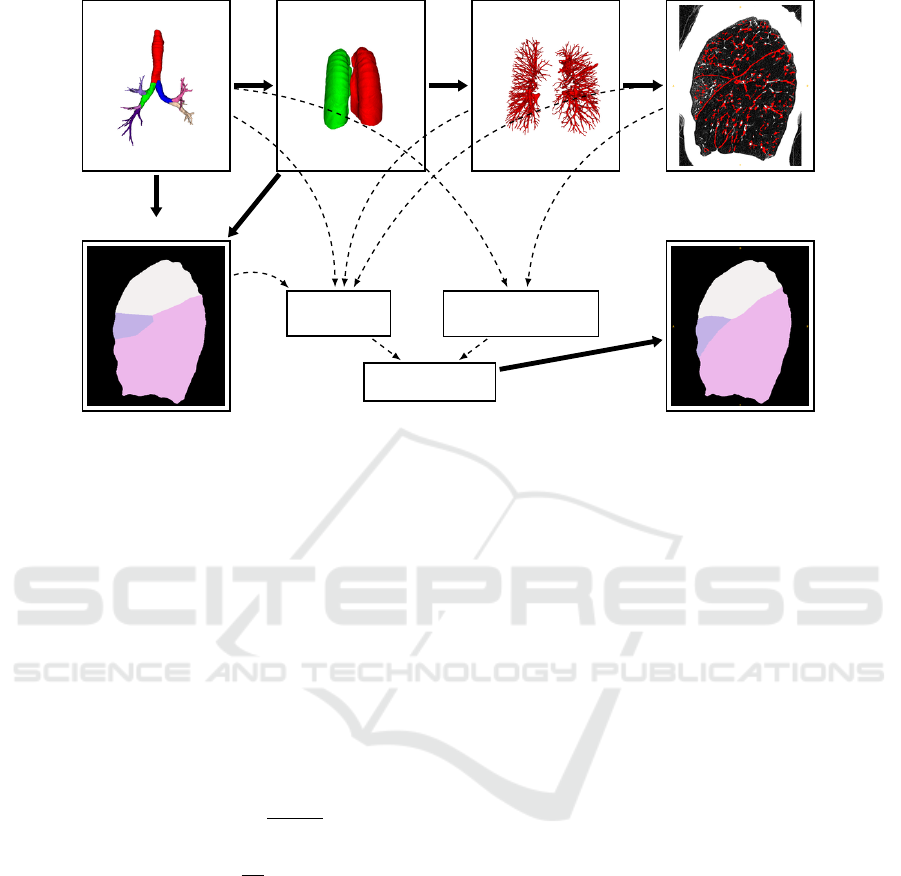
shape of lung lobes into account. Figure 1 shows
an overview of the algorithm. First the airway tree
and the lungs are segmented. After separating the
lungs into left and right lung, a segmentation of the
vessel trees is performed for each side. The fissures
are segmented in the next step by considering the
vessel trees. In the final step of the algorithm all
lung structures are combined in an energy equation,
which is then minimized using the α-expansion algo-
rithm (Boykov et al., 2001). The result is a 3D volume
where each voxel is assigned to one of five labels cor-
responding to the lobes.
2.1 Computing Lung Structures
In this section the computation of the airway, lung,
vessel and fissure segmentation is described.
2.1.1 Airways
The airway segmentation is a combination of two al-
gorithms. Using the first approach, initially a point
inside the trachea is detected by scanning for a dark
circle in the top-most slices. Starting from this point,
an iterative 3D-region growing algorithm is applied
to segment the airways (Helmberger et al., 2014).
The second airway segmentation is obtained by using
the PartialLungLabelMapImageFilter from the Chest
Imaging Platform (San Jose Estepar et al., 2015). As
each algorithm has its own strengths and performs
better in different cases they are combined to obtain
more stable results.
After obtaining an airway segmentation the
branches of the airway are labelled corresponding to
the lung lobes. In order to achieve this, the seg-
mentation first has to be skeletonized. Based on the
anatomical structure of the airway tree it is now pos-
sible to label the branches. This is done similar to
the method presented in (Gu et al., 2012). First an
undirected acyclic graph is extracted from the airway
skeleton. Starting from a root vertex at the trachea the
next branching point is found by looking for a vertex
with three neighbors. Having found the carina it is
now possible to separate the airway into left and right
lung. The left lung can easily be divided into upper
and lower lobe by finding the next branching point
and comparing the coordinates of the branches’ end
points. In the right lung the same approach is used for
three lobes.
2.1.2 Lungs
Similar to the airway segmentation, the lung seg-
mentation is a combination of two algorithms. First
the lung is segmented following a grey-level thresh-
olding (Otsu, 1979) approach with subsequent mor-
phological closing operations. In cases where this
approach fails the PartialLungLabelMapImageFilter
from the Chest Imaging Platform (San Jose Estepar
et al., 2015) is used.
With the help of the labelled airway segmentation,
the lung can now be separated into left and right lung.
2.1.3 Vessels
The algorithm by (Payer et al., 2016) is used for
the vessel segmentation. It is first enhancing vascu-
lar structures with a multiscale tubularity filter (Law
and Chung, 2008). Vessel paths are generated by
identifying regularly spaced local maxima in the ves-
sel enhanced images, which are connected to four-
dimensional tubular paths (Benmansour et al., 2013).
In the resulting local maxima graph a path for each
edge between its two end points is extracted that min-
imizes the geodesic distance. The tubular paths are
then filtered and grouped together to distinct vascular
subtrees. As we are not interested in knowing which
vessel is an artery or vein, the algorithm is stopped at
this point.
VISAPP 2018 - International Conference on Computer Vision Theory and Applications
388
Airways
Lungs
Vessels Fissures
Approx. Lobes
Optimal Lobes
D
p
( f
p
)
V
p,q
( f
p
, f
q
)
min(E( f ))
Figure 1: Overview of the segmentation pipeline. The airways, lungs, vessels and fissures are computed subsequently. The
airway segmentation is used to obtain an approximate lung lobe segmentation. All lung structures and the approximate seg-
mentation are then combined in an energy equation, which, leads to the optimal 3D lung lobe segmentation after minimization.
2.1.4 Fissures
Pulmonary fissures appear as sheet-like structures in
CT scans. Based on an eigenvalue analysis of the
Hessian matrix H, voxels that are part of a sheet-
like structure are enhanced. The eigenvalues of the
Hessian matrix are defined as |λ
1
| ≤ |λ
2
| ≤ |λ
3
|.
In (Lassen et al., 2013) the authors proposed a fis-
sure similarity measure S
Fissure
, which combines two
features F
Structure
and F
Sheet
:
S
Fissure
= F
Structure
· F
Sheet
(1)
F
Structure
= θ(−λ
3
)e
−(λ
3
−α)
6
β
6
(2)
F
Sheet
= e
−λ
6
2
γ
6
(3)
F
Structure
is used for finding structure in the image.
The parameters α and β in (2) are set to 50 and 35 re-
spectively. As fissures appear as bright structures on
a dark background the Heavyside function θ ensures
that voxels with an eigenvalue of λ
3
≥ 0 are not con-
sidered as fissures. F
Sheet
is used to capture sheet-like
structures. Vessels have larger λ
2
values than fissures
and are thus suppressed by this term. The parameter
γ is set to 25. The values for the presented parameters
were chosen according to the empirical analysis pre-
sented in (Lassen et al., 2013).
A mask of potential fissure voxels M
C
is constructed
by computing S
Fissure
for every voxel in the image and
by only keeping those voxels that satisfy S
Fissure
>
0.1. M
C
is then filtered by a 3D-vector-based con-
nected component analysis with a 6-neighborhood. In
case of a sheet the eigenvector corresponding to λ
3
points perpendicular to the direction of the structure.
This property is used to measure the similarity of ad-
jacent voxels by calculating the inner product of the
normalized eigenvectors of neighboring voxels. Two
neighboring voxels are considered as connected, if the
aforementioned inner product is larger or equal than
0.98. All components that are smaller than a thresh-
old are then rejected.
For the computation of H the differentiation is defined
as a convolution with derivatives of Gaussians (Frangi
et al., 1998). In (Lassen et al., 2013) the computa-
tion was done with σ = 1.0mm. In cases of patho-
logical lungs it often occurs that fissures are signifi-
cantly larger than in healthy lungs. Empirical analy-
sis showed that H computed with σ = 1.0 was often
too low to capture thick fissures. As our energy equa-
tion in (4) is fairly robust against false positives con-
cerning fissures, we favoured computing the fissure
segmentation on multiple scales for σ in the range
of [0.5 − 2.0]. This range has empirically shown to
detect fissures to a great extent on a variety of CT
datasets. These results on multiple scales are then
combined into a single image F
MS
. The drawback
of increasing σ to large values up to 2.0mm can lead
to a lot of vessels being falsely detected as fissures.
To circumvent this problem, the previously computed
vessel segmentation is dilated and subtracted from the
multiscale fissure segmentation F
MS
. Figure 2 on the
Pulmonary Lobe Segmentation in CT Images using Alpha-Expansion
389
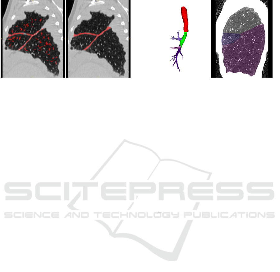
Figure 2: Left: Example for a fissure segmentation result
of a right lung with pathological thick fissures. While the
fissures are almost fully segmented, the result also contains
falsely detected structures. Right: A reference standard, in
which the fissures are fully segmented.
left shows a multiscale fissure segmentation result of
a right lung with pathological thick fissures.
2.2 Segmentation
The actual segmentation of the lung into its lobes
is achieved by computing an approximate solution,
which is then refined by minimizing an energy equa-
tion that contains information on the lung structures
computed in section 2.1.
2.2.1 Approximate Lobe Segmentation
An approximate lung lobe segmentation S
A
can be
obtained with the help of the airway tree. This is
achieved by taking the lobe based airway segmenta-
tion and computing a distance map on it. Voxels are
then assigned labels I
p
according to their nearest air-
way branch. This approach is leading to solutions in
good approximation, as the airway branches are typ-
ically centered in the lobes. Figure 3 on the right
shows an approximate lobe segmentation of a right
lung as overlay to the original CT image. On the left
in figure 3 the corresponding airway segmentation can
be seen.
2.2.2 Energy Equation
The anatomical structures that are described in sec-
tion 2.1 are combined in an energy equation of the
form:
E( f ) =
∑
p,q∈N
V
p,q
( f
p
, f
q
) +
∑
p∈P
D
p
( f
p
) (4)
In (4) the binary term V
p,q
is defining the energy that
is added to the system by two neighboring voxels
p and q with labels f
p
and f
q
. It is therefore often
referred to as interaction term. The unary term D
p
Figure 3: Left: Airway segmentation of a right lung; Right:
CT image (sagittal slice) of the same lung with the approx-
imate lobe labelling shown as overlay; the voxels are as-
signed labels corresponding to their nearest airway branch.
defines the energy for assigning a single voxel p the
value f
p
.
The minimization of (4) is consequently leading
to an optimal lobe segmentation. Boykov et al.
showed that the problem of minimizing energy
equations of the form presented in (4) is often
very difficult and finding the optimal solution is
NP-hard (Boykov et al., 2001). In the same work an
algorithm (α − expansion) for finding a local mini-
mum within a known factor to the global minimum
is presented. The α-expansion algorithm is based
on the computation of graph cuts. The cut separates
or segments the vertices of the graph into a set of α
and α vertices. The graph is constructed in a way
that α can only expand. By iterating over all labels
and setting α to the current label it is possible to find
solutions for images with multiple labels. The cost
of the graph cut represents the energy of the system.
Thus, only the solutions that undercut the current
lowest solution are kept in the iteration process. If
the algorithm converges, it is stopped.
The energy equation we propose for the lobe
segmentation using the anatomical structures of sec-
tion 2.1 is given by (4) where the binary term V
p,q
is
shown in (5) and the unary term D
p
in (6).
V
p,q
( f
p
, f
q
) = k
f
b
· P(a, b) (5)
D
p
( f
p
) = 0 if f
p
= I
p
= 1.0 ·k
f
· k
v
· k
a
if f
p
6= I
p
(6)
The unary term D
p
is set to 0 if the value f
p
of
voxel p equals the value I
p
in the approximate lobe
segmentation S
A
. Doing so the system is constrained
to stay relatively close to S
A
. The anatomical
information retrieved from the lung structures are
VISAPP 2018 - International Conference on Computer Vision Theory and Applications
390

Figure 4: Left: Vasculature of a right lung. The lobe bound-
aries can be guessed from regions devoid of vessels. Right:
An inverted distance map computed on the vasculature.
Dark regions denote regions with high fissure probability.
The real boundary is displayed as overlay.
incorporated into the unary term by the parameters
k
f
, k
v
and k
a
if f
p
6= I
p
.
The fissures are integrated by the parameter k
f
, which
equals to 0 if p ∈ F and otherwise to 1. This implies
that voxels that are part of fissures are equally likely
assigned to each label.
k
v
is a parameter to include information retrieved
from the lung vessels. A distance map is computed
based on the vessels. This distance map is inverted
and scaled to a range of [0, 1]. Voxels with a large
distance to the vessels have values close to 0, while
voxels part of the vessels have values of 1. Figure 4
on the left shows a vessel tree of a right lung. The
corresponding distance map is visualised on the right.
The true boundary is shown as an overlay on the
distance map.
The airway tree is considered by the third parameter
(k
a
) in (6). Two considerations regarding the airways
are made. First we assume that the accuracy of
the approximate lobe segmentation S
A
is higher in
regions that are in close proximity to the airways.
With increasing distance to the airways the certainty
for the correctness of the label for a given voxel
decreases. This property is represented by the param-
eter k
a
d
. The second consideration about the airways
is done regarding the relative distance between the
two nearest airway branches to the current voxel. If
a voxel is close to one branch and relatively far away
from the second nearest branch, then the certainty
that this voxel is assigned the right label is increased.
However, if a voxel lies almost inbetween two
branches the certainty is decreased. This property
is represented by the parameter k
a
r
. The two pa-
rameters for the airways are combined to k
a
= k
a
d
·k
a
r
.
P(a, b) in the binary term in (5) refers to the Potts
model (Wu, 1982). P(a, b) = k
p
if a 6= b and 0 oth-
erwise. By using the Potts model in the binary term
the system is pushed towards solutions with closed
structures and smooth boundaries. To favour segmen-
tations with boundaries on the fissures we include a
factor k
f
b
. This factor is always 1 except for voxels
that are part of the fissures, in which case k
f
b
= 0.
Therefore, boundaries on the fissures are more likely
to occur as they do not increase the energy. In regions
where no fissures are detected by the fissure segmen-
tation algorithm presented in section 2.1.4, the Potts
model leads to smooth interpolations of the indistinct
boundaries between the lung lobes.
3 EXPERIMENTS AND RESULTS
Two different experiments using two distinct datasets
were conducted.
3.1 Experiment 1
The first experiment was realised using a dataset of 25
CT images. Two independent and unbiased individu-
als who had been adequately trained and not been part
of the development of the algorithm, manually placed
approximately 500 markers along the fissures. Dis-
tinct markers were set for each fissure making an in-
dividual evaluation for the left oblique, right oblique
and right horizontal fissure possible. Distances be-
tween the manually placed markers on the fissures and
the closest lobe boundary in the segmentation were
determined as measure of segmentation accuracy. The
distances were measured as positive and negative de-
pending on the relative position of the markers and
the boundary resulting from the automatic lobe seg-
mentation. Regarding the left lung this led to positive
distances for markers that are part of the lower lobe in
the automatic segmentation and negative results for
markers that are part of the upper lobe. Consider-
ing the right lung negative values were either used for
markers of the horizontal fissure that were not part of
the middle lobe in the segmentation or markers of the
oblique fissure that were not part of the lower lobe.
Two out of a total of 25 CT images had been ex-
cluded because of undefined fissures in the image and
failing bronchus labelling, respectively. In two further
scans, no markers had been set for the right horizontal
fissure as it was not visible in the CT scans.
Using this evaluation protocol the median distance
was 0.00mm (interquartile range: -0.86-0.00mm).
The right and left oblique fissures median distances
were 0.00mm (0.00-0.80mm) and 0.00mm (-0.86-
0.00mm), respectively. The median distance for the
right horizontal fissure was 0.00mm (-1.05-0.00mm).
Pulmonary Lobe Segmentation in CT Images using Alpha-Expansion
391

The results for each individual case are visualised in
figure 5.
Using the same evaluation protocol with absolute
distances, the median distance was 1.04mm (0.88-
1.09mm). The right and left oblique fissures median
distances were 0.95mm (0.87-1.06mm) and 0.93mm
(0.87-1.05mm), respectively. The median distance
for the right horizontal fissure was 1.06mm (1.03-
1.09mm).
In figure 6 on the left, a lung lobe segmentation re-
sult for a left lung can be seen. On the right of figure 6
the result for the corresponding right lung is shown.
3.2 Experiment 2
Experiment 2 was conducted on the LObe and Lung
Analysis challenge (LOLA11) data set, which con-
tains 55 CT images from different clinically common
scanners and protocols. It includes many cases with
severe pathologies, which makes a segmentation chal-
lenging for automatic algorithms. In cases where the
airway segmentation failed or produced results con-
taining missing airway branches with respect to the
lobes, a manual correction had been performed. A
quantitative (see table 1) as well as a qualitative eval-
uation, by visual inspection, of the segmentation re-
sults on the LOLA11 dataset shows promising results
even on pathological lungs.
Figure 7 shows the results for the left and right lung of
case 42. Even though the left lung contains focal re-
gions of emphysema, the result shows a very precise
segmentation. The result for the right lung shows a
good segmentation even in regions where the oblique
fissure is incomplete.
On the right in figure 8 the segmentation result for
the right lung of case 13 is visualised. It shows the
slice of the same right lung shown in figure 3. Start-
ing from the initial segmentation in figure 3 the final
result follows perfectly the fissures. On the left in fig-
ure 8 the result for the left lung of case 1 is shown.
Two different challenging cases regarding the lobe
segmentation are shown in figure 9. On the left, the
left lung of case 6 is shown. The lung shows an exam-
ple for lung fibrosis together with regions of emphy-
sema and a bulla. Due to these severe pathologies, the
upper lobe is uncommonly small. In conjunction with
a poor airway segmentation this leads to an approxi-
mate lobe segmentation that is far away from the opti-
mal, thus resulting in a weak segmentation of the pul-
monary lobes. On the right the result for the right lung
of case 54 is shown. While the segmentation is very
precise with respect to the right oblique fissure, the
segmentation of the middle lobe is not correct. This
can be explained by a weak approximate segmenta-
Table 1: Results of lobe segmentation for the 55 scans in
the LOLA11 challenge.
LU LL RU RM RL
mean 0.929 0.884 0.873 0.714 0.928
SD 0.118 0.231 0.169 0.322 0.104
min 0.272 0 0 0 0.341
Q1 0.922 0.919 0.853 0.575 0.909
median 0.971 0.965 0.938 0.863 0.973
Q3 0.991 0.983 0.977 0.941 0.983
max 0.997 0.993 0.996 0.994 0.995
score: 0.866
tion, which was derived from an already weak airway
segmentation.
With a score of 0.866, our algorithm performs in the
range of the other state-of-the-art methods. Merely
the interactive approaches show distinctly better re-
sults (LOLA11, 2017). Detailed comparisons to other
methods are difficult to perform, as labelled datasets
for lobe segmentation are not publicly available.
4 CONCLUSION AND FUTURE
WORK
In this paper, we have proposed a new algorithm
for fully automatic lung lobe segmentation using α-
expansion. This approach allows to combine anatom-
ical structures, derived from the original CT image,
as well as prior knowledge on the shape of lung lobes
into an energy equation. The Potts model is used as
prior knowledge, which is leading to smooth lobar
surfaces. An initial approximation to the lung lobe
segmentation, close to the actual segmentation, is first
derived by computing a distance map on the labelled
airway segmentation. The multiscale fissure segmen-
tation approach is drastically improving the amount of
detected fissures while simultaneously increasing the
amount of spuriously detected structures. False posi-
tives in the fissure segmentation are however no issue
regarding the final lobe segmentation as the system
stays close to the initial approximation. Thus finding
a good approximation is important to achieve good
results, which is evident from the observation that a
poor segmentation is almost always attributable to a
weak approximate lobe segmentation.
While limitations in our method are seen in the
airway and lung segmentation steps, which consist
of the combination of two algorithms to yield robust
results, the approach of minimizing the devised
energy equation has shown good results for lobe
segmentation in our experiments.
VISAPP 2018 - International Conference on Computer Vision Theory and Applications
392
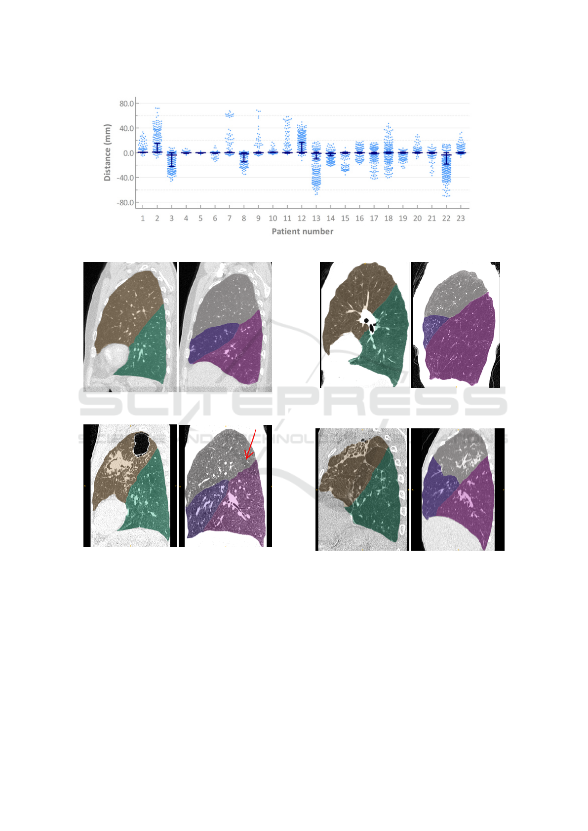
Figure 5: Distances of the individual markers from the nearest automatically detected fissure for each patient in experiment 1.
Figure 6: Example for a segmentation result of a left lung
(left) and a right lung (right) a patient from experiment 1.
Figure 7: Segmentation results for LOLA11 case 42. Note
the invisible fissure (arrow).
With this work we established a general method
with modular components as suggested in (Doel et al.,
2015). Future work will consist of gradually improv-
ing the individual modules for lung, vessel, fissure
and especially airway segmentation.
ACKNOWLEDGEMENTS
The assistance of Grazyna Kwapiszewska is highly
appreciated.
Figure 8: Left: Segmentation result for the left lung of
LOLA11 case 1. Right: Segmentation result for the right
lung of LOLA11 case 13.
Figure 9: Left: Segmentation result for the left lung of
LOLA11 case 6. Right: Segmentation result for the right
lung of LOLA11 case 54.
REFERENCES
Aziz, A., Ashizawa, K., Nagaoki, K., and Hayashi, K.
(2004). High resolution CT anatomy of the pulmonary
fissures. Journal of thoracic imaging, 19(3):186–191.
Benmansour, F., T
¨
uretken, E., and Fua, P. (2013). Tubular
geodesics using oriented flux: An ITK implementa-
tion. The Insight Journal.
Boykov, Y., Veksler, O., and Zabih, R. (2001). Fast ap-
proximate energy minimization via graph cuts. IEEE
Pulmonary Lobe Segmentation in CT Images using Alpha-Expansion
393

Transactions on pattern analysis and machine intelli-
gence, 23(11):1222–1239.
Bragman, F. J., McClelland, J. R., Jacob, J., Hurst, J. R.,
and Hawkes, D. J. (2017). Pulmonary lobe segmen-
tation with probabilistic segmentation of the fissures
and a groupwise fissure prior. IEEE Transactions on
medical imaging, 36(8):1650–1663.
Doel, T., Gavaghan, D. J., and Grau, V. (2015). Review
of automatic pulmonary lobe segmentation methods
from CT. Computerized Medical Imaging and Graph-
ics, 40:13–29.
Doel, T., Matin, T. N., Gleeson, F. V., Gavaghan, D. J., and
Grau, V. (2012). Pulmonary lobe segmentation from
CT images using fissureness, airways, vessels and
multilevel B-splines. In 9th IEEE International Sym-
posium on Biomedical Imaging (ISBI), 2012, pages
1491–1494. IEEE.
Frangi, A. F., Niessen, W. J., Vincken, K. L., and Viergever,
M. A. (1998). Multiscale vessel enhancement fil-
tering. In International Conference on Medical Im-
age Computing and Computer-Assisted Intervention,
pages 130–137. Springer.
Gu, S., Wang, Z., Siegfried, J. M., Wilson, D., Bigbee,
W. L., and Pu, J. (2012). Automated lobe-based air-
way labeling. Journal of Biomedical Imaging, 2012:1.
Hayashi, K., Aziz, A., Ashizawa, K., Hayashi, H., Na-
gaoki, K., and Otsuji, H. (2001). Radiographic and
CT appearances of the major fissures. Radiographics,
21(4):861–874.
Helmberger, M., Pienn, M., Urschler, M., Kullnig, P., Stoll-
berger, R., Kovacs, G., Olschewski, A., Olschewski,
H., and B
´
alint, Z. (2014). Quantification of tortuosity
and fractal dimension of the lung vessels in pulmonary
hypertension patients. PloS one, 9(1):e87515.
Lassen, B., van Rikxoort, E. M., Schmidt, M., Kerkstra, S.,
van Ginneken, B., and Kuhnigk, J.-M. (2013). Au-
tomatic segmentation of the pulmonary lobes from
chest CT scans based on fissures, vessels, and bronchi.
IEEE Transactions on medical imaging, 32(2):210–
222.
Lassen-Schmidt, B. C., Kuhnigk, J.-M., Konrad, O., van
Ginneken, B., and van Rikxoort, E. M. (2017). Fast
interactive segmentation of the pulmonary lobes from
thoracic computed tomography data. Physics in
Medicine and Biology, 62(16):6649.
Law, M. W. K. and Chung, A. C. S. (2008). Three Dimen-
sional Curvilinear Structure Detection Using Opti-
mally Oriented Flux, pages 368–382. Springer Berlin
Heidelberg, Berlin, Heidelberg.
LOLA11 (2017). [Online; accessed 30-October-2017].
Otsu, N. (1979). A threshold selection method from gray-
level histograms. IEEE Transactions on systems, man,
and cybernetics, 9(1):62–66.
Payer, C., Pienn, M., B
´
alint, Z., Shekhovtsov, A., Talakic,
E., Nagy, E., Olschewski, A., Olschewski, H., and
Urschler, M. (2016). Automated integer programming
based separation of arteries and veins from thoracic
CT images. Medical image analysis, 34:109–122.
San Jose Estepar, R., Ross, J. C., Harmouche, R., Onieva, J.,
Diaz, A. A., and Washko, G. R. (2015). Chest imag-
ing platform: an open-source library and workstation
for quantitative chest imaging. In C66. Lung imag-
ing II: New probes and emerging technologies, pages
A4975–A4975. Am Thoracic Soc.
Schuhmann, M., Raffy, P., Yin, Y., Gompelmann, D., Oguz,
I., Eberhardt, R., Hornberg, D., Heussel, C. P., Wood,
S., and Herth, F. J. (2015). Computed tomography
predictors of response to endobronchial valve lung re-
duction treatment. comparison with chartis. Ameri-
can journal of respiratory and critical care medicine,
191(7):767–774.
Tanabe, N., Muro, S., Tanaka, S., Sato, S., Oguma, T.,
Kiyokawa, H., Takahashi, T., Kinose, D., Hoshino,
Y., Kubo, T., Ogawa, E., Hirai, T., and Mishima, M.
(2012). Emphysema distribution and annual changes
in pulmonary function in male patients with chronic
obstructive pulmonary disease. Respiratory research,
13(1):31.
Van Rikxoort, E. M., Prokop, M., de Hoop, B., Viergever,
M. A., Pluim, J. P., and van Ginneken, B. (2010).
Automatic segmentation of pulmonary lobes robust
against incomplete fissures. IEEE Transactions on
medical imaging, 29(6):1286–1296.
Weder, W., Thurnheer, R., Stammberger, U., B
¨
urge, M.,
Russi, E. W., and Bloch, K. E. (1997). Radiologic
emphysema morphology is associated with outcome
after surgical lung volume reduction. The Annals of
thoracic surgery, 64(2):313–320.
Wu, F. Y. (1982). The Potts model. Reviews of Modern
Physics, 54:235–268.
Zhang, L., Hoffman, E. A., and Reinhardt, J. M. (2006).
Atlas-driven lung lobe segmentation in volumetric X-
ray CT images. IEEE Transactions on medical imag-
ing, 25(1):1–16.
VISAPP 2018 - International Conference on Computer Vision Theory and Applications
394
