
VIOL: Viewpoint Invariant Object Localizator
Viewpoint Invariant Planar Features in Man-Made Environments
Marco Filax and Frank Ortmeier
Chair of Software Engineering, Otto von Guericke University Magdeburg, Magdeburg, Germany
Keywords:
Pervasive Smart Camera, Object Localization, Projective Distortion, Scene Understanding.
Abstract:
Object detection is one of the fundamental issues in computer vision. The established methods, rely on diffe-
rent feature descriptors to determine correspondences between significant image points. However, they do not
provide reliable results, especially for extreme viewpoint changes. This is because feature descriptors do not
adhere to the projective distortion introduced with an extreme viewpoint change. Different approaches have
been proposed to lower this hurdle, e.g., by randomly sampling multiple virtual viewpoints. However, these
methods are either computationally intensive or impose strong assumptions of the environment. In this paper,
we propose an algorithm to detect corresponding quasi-planar objects in man-made environments. We make
use of the observation that these environments typically contain rectangular structures. We exploit the infor-
mation gathered from a depth sensor to detect planar regions. With these, we unwrap the projective distortion,
by transforming the planar patch into a fronto-parallel view. We demonstrate the feasibility and capabilities of
our approach in a real-world scenario: a supermarket.
1 INTRODUCTION
Object detection is one of the fundamental issues in
computer vision. The problem can be summarized
as finding objects in an image using a known image
of the same object, e. g., localizing an item within
a supermarket. The general idea relies on corre-
spondences: matches that link significant points from
one image to another. These feature corresponden-
ces are also required for a variety of other applicati-
ons including Visual Odometry (Nister et al., 2006),
Image Stitching (Brown and Lowe, 2007), or Object
Tracking (Donoser et al., 2010). All of these applica-
tions typically require a significant number of corre-
spondences.
A variety of different feature detection and des-
cription frameworks has been developed, e. g., Maxi-
mally Stable Extremal Regions (Matas et al., 2002),
Scale Invariant Feature Transform (SIFT) (Lowe,
2004), Speeded Up Robust Features (SURF) (Bay
et al., 2008), or Oriented FAST and Rotated BRIEF
(ORB) (Rublee et al., 2011). They all share a common
idea: features shall be distinctive against their spatial
surroundings. Typically, feature matching algorithms
are divided into three steps: i) significant points or re-
gions within an image are detected, ii) these detected
features are described with respect to their spatial sur-
(a) Fronto-parallel view of
different items within a shelf.
(b) Slanted view of the same
items within the same shelf.
Figure 1: While it is possible to detect different items in
Figure 1(a) it is quite challenging to detect these objects in
Figure 1(b). This is because SIFT does not adheres to the
projective distortion introduced with the viewpoint change.
roundings, iii) and finally, these descriptions are ma-
tched to find correspondences between two different
images.
If the viewpoint change from one image to another
is reasonably small, state-of-the-art feature detection
algorithms typically produce reliable and repeatable
results. If the viewpoint change is large enough, the
problem of matching features becomes challenging.
Morel and Yu demonstrated that the established met-
hods, e. g., SIFT as one of the de-facto-standards in
this area, do not give suitable results if the viewpoint
change is strong (Morel and Yu, 2009). This is be-
cause feature descriptors typically aim at providing
a scale, rotation, and illumination invariant descrip-
tion. However, state-of-the-art descriptors do not ad-
Filax, M. and Ortmeier, F.
VIOL: Viewpoint Invariant Object Localizator - Viewpoint Invariant Planar Features in Man-Made Environments.
DOI: 10.5220/0006624005810588
In Proceedings of the 13th International Joint Conference on Computer Vision, Imaging and Computer Graphics Theory and Applications (VISIGRAPP 2018) - Volume 4: VISAPP, pages
581-588
ISBN: 978-989-758-290-5
Copyright © 2018 by SCITEPRESS – Science and Technology Publications, Lda. All rights reserved
581

here to the projective distortion introduced by view-
point changes of the camera, as illustrated in Figure 1.
Figure 1(a) illustrates an example from the super-
market: a shelf containing different items. Here, a
viewpoint has been chosen, close to a fronto-parallel
view - the camera is positioned close to the opposite
normal direction of the plane defined by the shelf. De-
termining corresponding feature points in this image
and an image from a database typically produces good
results and demonstrates the applicability of state-of-
the-art algorithms.
If the viewpoint of the camera is moved as shown
in Figure 1(b), the number of correspondences dra-
matically decreases due to the projective distortion
introduced through the viewpoint change. This ob-
servation can be justified by evaluating state-of-the-
art feature descriptors: they typically consider a fea-
ture point as a local distinctive element on the image
plane. If the image plane is nearly co-planar with the
object plane in one image, whereas it is not in another
image, the descriptions of the same physical point on
the object plane differ and thus do correspond.
In this paper, we extend the capabilities of state-
of-the-art feature matching frameworks. Therefore,
we focus on objects in man-made environments. We
make use of the observation that man-made envi-
ronments are rich of planar, rectangular structures.
This is because they typically contain some sort of
structured objects, e. g., walls, windows, shelves, or
paintings. We exploit this observation with Micro-
softs HoloLens to detect planar rectangles within
the image. We use these to recover a fronto-parallel
view to reduce the projective distortion. We call these
fronto-parallel views viewpoint invariant planes. Ba-
sed on these, we compute SIFT features to achieve
viewpoint invariance of the SIFT descriptors. We ge-
nerate viewpoint invariant planes relying only on the
vertices of the planar rectangles. We demonstrate the
feasibility of our approach in a real-world scenario: a
supermarket. Further, we show similarities and diffe-
rences to other state-of-the-art viewpoint invariant fe-
ature matching frameworks. We address in particular
extreme viewpoint changes to evaluate the viewpoint-
variance of our approach.
Our contribution is two-folded. On the one hand,
we propose a straight forward system to achieve vie-
wpoint invariance for man-made planar objects. The-
reby, we describe how the proposed approach can be
integrated into a modern mixed reality device. On the
other hand, we do not impose constraints on our envi-
ronment, except for that it contains planar elements.
In contrast to other approaches, we do not restrict
our environment by imposing a Manhattan-world as-
sumption.
The paper is structured as follows: We present re-
lated work of other authors in Section 2. Afterwards,
in Section 3, we describe the proposed method to de-
tect viewpoint invariant features with the help of vie-
wpoint invariant planes. In Section 4 we evaluate the
proposed method in our real world scenario. We con-
clude our work in Section 5.
2 RELATED WORK
In this section, we summarize existing approaches
specifically designed for projectively distorted scenes.
We distinguish two types of methods: those that rely
on the pure image data and those that additionally use
depth data.
An approach of the first category was proposed by
Morel and Yu. They proposed an affine invariant fea-
ture matching approach (Morel and Yu, 2009; Yu and
Morel, 2009) - an extension of the well-known SIFT
framework (Lowe, 1999). Different viewpoints are
simulated by sampling different longitudes and latitu-
des of a view-hemisphere over the image. The aut-
hors propose to calculate an affine transformation to
unwrap the projective distortion. SIFT features of si-
mulated views are matched and the highest amount
of matches represents the result. Cai et al. propo-
sed a similar approach (Cai et al., 2013). Here, the
authors calculate a homography to unwrap the pro-
jective distortion. Both approaches cannot determine
correct correspondences if multiple planes are visible
on a single image. Further, they are computationally
intensive due to the subsequent matching of simulated
views.
To relax the computationally complexity, an ite-
rative approach has been proposed (Yu et al., 2012).
The approach has a significant drawback: its success
is based on the initial matching of the two images. If,
e. g., because of a strong viewpoint change, matching
fails, the algorithm is not able to produce reliable re-
sults. Chen et. al. proposed to extract MSER (Matas
et al., 2004) and fit them into ellipses (Chen et al.,
2013). These ellipses are assumed to be circular in a
fronto-parallel view. Thus, they transform them into
circular areas and describe and match SIFT features.
After all, especially for man-made environments,
rectangular areas are more likely, e. g., for doors, win-
dows, shelves, and building facades. This observa-
tion can be intensified by incorporating the Manhattan
world assumption, whereby it is assumed that a scene
contains sufficient structure to align planes to three
orthogonal directions (Yuille and Coughlan, 2000).
(Srajer et al., 2015) exploit this assumption. The aut-
hors propose to estimate the room geometry by fit-
VISAPP 2018 - International Conference on Computer Vision Theory and Applications
582
ting a textured 3D cuboid into the scene. Finally, they
rectify the individual cuboid surfaces and determine
SIFT correspondences. However, this permits usage
in a Non-Manhattan World. Filax et al. proposed
QuadSIFT (Filax et al., 2017). Here, the authors pro-
posed to detect quadrilaterals, unwrap them to rec-
tangles and determine SIFT correspondences. The
approach does not incorporate a Manhattan-world as-
sumption, but this raises additional difficulties in de-
tecting quadrilaterals.
An approach of the second category was publis-
hed by K
¨
oser and Koch. They proposed a perspecti-
vely invariant feature descriptor for local regions that
can be approximated by a plane relying on depth
data (K
¨
oser and Koch, 2007). Based on MSER (Ma-
tas et al., 2004), a fronto-parallel view is generated
for every detected feature. Therefor, the 3D points
are meshed and textured from the original view. Af-
terwards a virtual camera is moved to a position in
normal direction from the surface. Finally, every fe-
ature in the synthetic view is described via SIFT. Wu
et al. proposed a quite similar approach, the idea is to
calculate a tangent plane for every feature point (Wu
et al., 2008). In contrast to (K
¨
oser and Koch, 2007),
they propose to detect features via SIFT directly in
the query image. By projecting the texture of the 3D
model onto a tangent plane at every feature point, they
gain the ability to unwrap the projective distortion. Fi-
nally, they calculate the descriptors based on the synt-
hetic projections and and determine correspondences.
However, SIFT also detects features at edges where
an approximation of the tangent plane within the 3D
model might be unreliable.
Another approach of the second category was pro-
posed by Baatz et al.. Their system was designed
for place-of-interest recognition in an urban environ-
ment (Baatz et al., 2010). Their system requires an
offline data acquisition phase to determine the urban
3D geometry and build a database of fronto-parallel
synthetic views of buildings. In the recognition phase
they propose to detect line segments and to unwrap
the projective distortion by using Manhattan-world
assumption similar to (McDonald, 2009). The aut-
hors rectified an image according to pairs of vanishing
points. Finally, they compute SIFT features to deter-
mine correspondences with the database. However,
this approach requires a query image which is rich
of line segments. Further, it is desirable that most of
the line segments correspond to orthogonal vanishing
points. Again, this approach permits usage in a Non-
Manhattan-world scene.
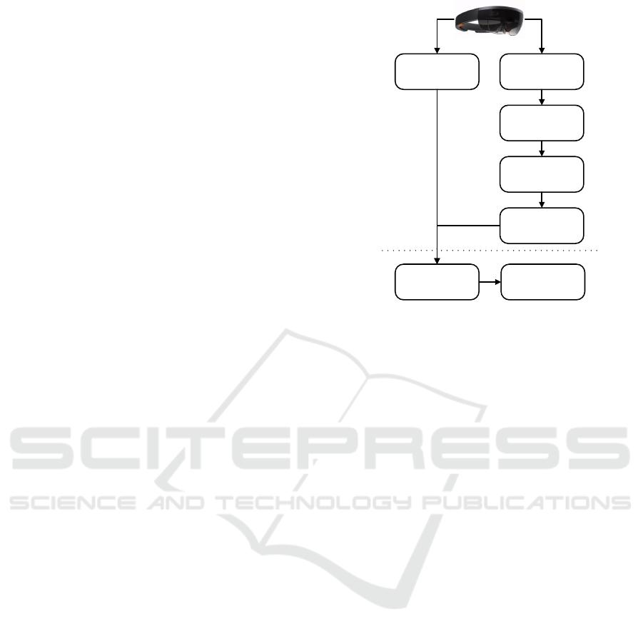
1) Acquire Local
Geometry
2) Detect Planar
Structures
3) Select Visible
Planes
4) Acquire 2D
Projection
0) Acquire Image
5) Viewpiont
Invariant Planes
6) SIFT Features
Online
Offline
Figure 2: VIOL: We use the 3D model gathered with a Ho-
loLens to achieve viewpoint invariance of features. There-
fore, we unwrap locally planar rectangles within an image
to fronto-parallel views - so called viewpoint invariant pla-
nes. Finally, we detect and describe SIFT features on them.
3 VIEWPOINT INVARIANT
OBJECT LOCALIZATOR
In this section, we describe our system VIOL, which
was designed to detect objects in an unknown man-
made environment using Microsofts HoloLens. To
the current day, the HoloLens is one of the most
famous, publicly available, head-mounted devices
which acquires a model of the environment. Diffe-
rent cameras and an inertial measurement unit track
the users head movements, aided by a time-of-flight
depth sensor. The sensor data is used to triangulate
the environment. The generated map is refined and
extend as the user moves.
The generated map in combination with 2D ima-
ges are the enabling techniques for our system. The
goal of VIOL is to determine the position of different
objects. The goal adheres an everyday use-case: sear-
ching for items in a supermarket.
However, especially in an unknown supermarket,
this is only helpful, if VIOL is able to detect objects
reliably. This is especially true for objects distorted
due to a slanted view as shown in Fig. 1(b). We ex-
tend SIFT to cope with projective distortion: first, we
detect planar rectangular structures using 3D sensor
data. Then, we determine the rectangles that are visi-
ble to the camera and project them onto the camera
image. Finally, we compute a viewpoint invariant
plane for every projected rectangle and finally extract
VIOL: Viewpoint Invariant Object Localizator - Viewpoint Invariant Planar Features in Man-Made Environments
583

viewpoint invariant SIFT features. An outline of the
proposed approach is depicted in Fig. 2. In the follo-
wing, we explain every step in detail.
3.1 Acquire Local Geometry
VIOL relies on a 3D model of the environment. The
first step of the approach consists of acquiring the
local geometry with the built-sensors. We designed
our VIOL explicitly for the use with Microsofts Ho-
loLens. The head-tracking cameras, inertial measure-
ment units, and time-of-flight depth sensor are used
to acquire a 3D mesh of the environment. As the
user continues to move, the triangular mesh is con-
tinuously grows.
3.2 Detect Planar Structures
In the second step, we detect planar, physical structu-
res. Planar regions within the scene are of interest as
they are most resistant to occlusion. If a region within
the scene is planar, it is not likely to change its visual
appearance under strong projective distortion.
We detect planar regions in the previously gene-
rated 3D triangular mesh of the environment. We use
the publicly available source from Microsoft
1
. First,
the curvature for every vertex of the mesh is calcu-
lated. Second, the curvatures for every vertex are
smoothed to adhere to noise. Next, potential pla-
nes are found by flood-filling over the vertex curva-
tures. Neighboring vertices are considered as poten-
tially planar if the curvature at every vertex and the
difference of two neighboring normals are reasonable
small. Then, the plane equations of found potential
planes are determined via Principal Component Ana-
lysis. Using the plane equations, the area of the po-
tential planes is extended using vertices, that are close
to the plane. Finally, rectilinearity is enforced by de-
termining an oriented bound box for every plane can-
didate.
3.3 Select Visible Planes
The 3D model of the environment continuously
grows, due to the nature of the HoloLens. Therefore,
not every previously detected plane might be visible
for the user. As we aim at comparing visual features
within the planes, we do not have to process invisible
planes.
In this step, we determine the subset of visible pla-
nes with respect to the current viewpoint of the ca-
mera. To achieve this, we select visible planes by pro-
jecting multiple rays from the camera center through
1
https://github.com/Microsoft/MixedRealityToolkit
the image plane. We divide the image into different
cells and project a ray through the center of every cell.
Finally, we build the set of visible planes, by selecting
the closest 3D planar rectangles which intersect with
at least one ray.
3.4 Acquire 2D Projection
In this step, we project the vertices of the 3D planar
rectangles onto the image plane. Speaking mathema-
tically, projecting an arbitrary point into the image
space can be expressed as
˜x = K(RX + T ) (1)
whereas X represents the point in 3D and ˜x the pro-
jected point on the image plane. K encapsulates the
internal parameters and R and T represent the external
parameters: camera rotation, and translation (Hartley
and Zisserman, 2004).
We project the 3D vertices of visual planes, de-
fined in the 3D mesh of the environment, onto the
image plane with Equation 1. We thereby obtain the
pixel coordinates of the plane. Note, that projecting
a 3D planar rectangle onto the image plane introdu-
ces projective distortion. Thereby, the 3D rectangles
looses some properties in image space, e. g., rectiline-
arity. The 3D rectangle, projected into a 2D quadri-
lateral, is typically not rectangular in image space. In
the following phases, we unwrap the projective dis-
tortion introduced through the projection.
3.5 Viewpoint Invariant Planes
In the previous step, we projected physically planar
rectangles into image space, whereby they lose sig-
nificant properties, such as rectilinearity. We reco-
ver this property by unwrapping the projected plane
into a viewpoint invariant plane. Therefore, we de-
termine a homography that maps the projected rec-
tangular, the quadrilateral, into a viewpoint invariant
plane. We calculate the homography, mapping a gi-
ven set of at least four points into another set of four
points, with the well-known Direct Linear Transfor-
mation algorithm (Hartley and Zisserman, 2004). We
use the vertices of the quadrilateral and the vertices
of the viewpoint invariant plane to estimate the ho-
mography. We unwrap the projective distortion of the
planar object by applying the homography to every
rectangle that has been projected into a quadrilateral
in image space.
Before we can apply the homography, we have to
estimate it. Therefore, we need to estimate a valid set
of vertices of the viewpoint invariant plane in image
space. We require a viewpoint invariant plane to have
VISAPP 2018 - International Conference on Computer Vision Theory and Applications
584

rectangular vertices in image space. Therefore, we
might simply choose the vertices as a squared patch
of an arbitrary size. Although this recovers the rectili-
nearity, it does not preserve the physical aspect ratio.
As we pointed out in (Filax et al., 2017), it is impor-
tant to preserve the aspect ratio, as it enhances the
matching results dramatically. Due to the sensor data
of the HoloLens, we do have access to the physical as-
pect ratio of every 3D plane. Thus, we determine the
set of rectangular vertices with respect to the physical
aspect ratio of every 3D plane.
Due to its nature, a homography is typically de-
fined up to scale. Thus, the scale of the rectangular
set of vertices can freely be chosen. Although fea-
ture descriptors typically adhere changes to scale, we
choose to fix the scale of every viewpoint invariant
plane with respect to the physical size of the corre-
sponding 3D plane. We fixed the scale for every vie-
wpoint invariant plane to 20 dots per inch.
3.6 Detect, Describe and Match SIFT
Features
We use SIFT (Lowe, 2004) to detect and describe fe-
atures of two viewpoint invariant planes. We rely on
OpenCV to detect and describe SIFT features using
the default parameters in combination with a brute
force matching strategy. To detect if a descriptor in
one viewpoint invariant plane matches another des-
criptor in the other viewpoint invariant plane we fol-
low Lowe’s well-known ratio test: If the nearest dis-
tance of the best match for a descriptor is smaller
than k times the second best match for that descrip-
tor, the best match is considered to be valid with
k = 0.6 (Lowe, 2004). Next, we remove invalid mat-
ches with a reprojection error of 4.0 pixels and larger.
Finally, we consider two images as matching if the
number of correspondences is larger than six.
4 EXPERIMENTS
We evaluate our method with real world images ta-
ken in a local supermarket. Our database comprises
two different arbitrarily selected shelves. Fig. 3 de-
picts examples. These images were taken with the
camera of Microsofts HoloLens and have a resolution
of 1280x720 pixels. Note that we used the grayscale
images to preserve the comparability between the dif-
ferent approaches. The images were taken from va-
rious viewpoints in an unstructured manner to mimic
natural behavior.
Our evaluation is two-folded: on the one hand,
we detect correspondences between different images
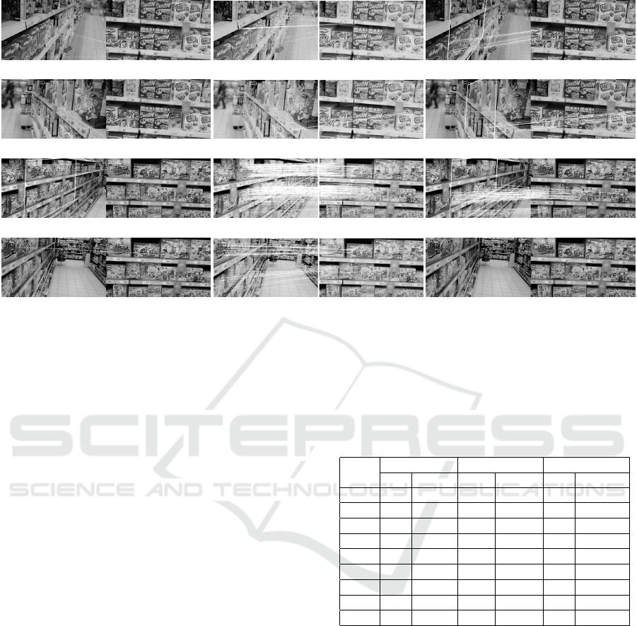
(a) Fronto-parallel view of a
shelf whereas Φ u 0
◦
.
(b) Slanted view of the same
shelf with Φ u 50
◦
.
(c) Fronto-parallel view of
another shelf with Φ u 0
◦
.
(d) Slanted view of Fi-
gure 3(c) with Φ u −50
◦
.
Figure 3: Examples from the database: Figure 3(a) depicts
a fronto-parallel view of a shelf with cereals. In Figure 3(b)
the viewpoint was changed. Figure 3(c) depicts another
shelf. This shelf does not contain repetitive items as the
shelf in 3(a). Figure 3(d) depicts a slanted view of 3(c).
Note, that we blurred the images after the evaluation.
from arbitrary viewpoints of the shelf. On the other
hand, we recognize objects within these shelves. We
determine the quality of our approach by determining
the total number of correspondences found. We com-
pare the proposed method with SIFT (Lowe, 2004)
and ASIFT (Yu and Morel, 2011). Note, that these
methods do not rel y on 3D data, but seem to be the
de-facto standard in this particular field of research.
4.1 Shelf Detection
We evaluate our method by matching different scene
images in a man-made environment in this section.
Table 1 comprises the results for the scene Cereals.
Example images are depicted in Figure 3(a) and Fi-
Table 1: Quantitative evaluation of SIFT, ASIFT and VIOL
for the shelf Cereals. Φ denotes the estimated viewpoint
change with respect to the shelf in Figure 3(a). M deno-
tes the absolute number of correspondences and R comprise
this value with respect to the cardinality of features in Fi-
gure 3(a).
Φ
SIFT ASIFT VIOL
M R M R M R
−50
◦
4 0,05% 40 0,09% 23 0,37%
−45
◦
2 0,02% 25 0,06% 32 0,52%
−30
◦
16 0,18% 77 0,18% 101 1,65%
20
◦
64 0,74% 750 1,76% 269 4,38%
30
◦
20 0,23% 509 1,19% 164 2,67%
35
◦
10 0,11% 452 1,06% 134 2,18%
45
◦
5 0,06% 218 0,51% 92 1,50%
50
◦
7 0,08% 109 0,26% 64 1,04%
55
◦
4 0,05% 22 0,05% 33 0,54%
VIOL: Viewpoint Invariant Object Localizator - Viewpoint Invariant Planar Features in Man-Made Environments
585
(a) SIFT (4/0,05%) (b) ASIFT (40/0,09%) (c) VIOL (23/0,37%)
(d) SIFT (4/ 0,05%) (e) ASIFT (22/0,05%) (f) VIOL (33/0.54%)
(g) SIFT (8/0,09%) (h) ASIFT (697/1,51%) (i) VIOL (159/2,94%)
(j) SIFT (4/0,05%) (k) ASIFT (178/0,38%) (l) VIOL (0/0,00%)
Figure 4: Typical examples from our scene detection test sets. The first column depicts the result of the state-of-the-art
approach. The second column depicts results generated by ASIFT and the last column depicts our results. We denote the
absolute number of correspondences M and the detection rate R in brackets for every approach.
gure 3(b). The first column depicts the estimated vie-
wpoint change with respect to the shelf in Figure 3(a).
M denotes the absolute number of correspondences
whereas R comprises the absolute values with respect
to the absolute number of features extracted from Fi-
gure 3(a).
As indicated with bold values: ASIFT outper-
forms the other approaches in terms of absolute fe-
ature correspondences. This becomes clear if we put
it into the context of detected features. SIFT, for in-
stance, detected 8700 features in Figure 3(a). VIOL
computes 6138 because our approach does not incor-
porate features that do not belong to a plane. ASIFT
detects 42.601 features in Figure 3(a) because it in-
corporates a two-resolution procedure and uses the
implementation of Lowe and whereas we rely on
OpenCV (for SIFT and VIOL). To overcome this, we
choose to display the detection rate R.
R describes the percentage of correspondences
with respect to the cardinality features in the fronto-
parallel image. VIOL outperforms the other approa-
ches here as shown in Table 1. This because VIOL
does not estimate the projection from one image to
another, due to the fact that we use the 3D informa-
tion to measure the projection, our viewpoint invari-
ant plane is not subject to protective distortion.
The same observation is present in the second test
set Lego. Table 2 depicts the results. ASIFT outper-
forms the other approaches generally in terms of the
absolute number of correspondences. Again, this is
due to the fact, that ASIFT detects more features in
Table 2: Quantitative evaluation of SIFT, ASIFT and VIOL
for the shelf Lego. Here, the different images are matched
with Figure 3(c). The notation is equivalent to Table 1. Bold
numbers represent the best results for the given set of ima-
ges.
Φ
SIFT ASIFT VIOL
M R M R M R
−70
◦
4 0,05% 178 0,38% 0 0,00%
−60
◦
4 0,05% 0 0,00% 14 0,26%
−50
◦
6 0,07% 195 0,42% 44 0,81%
−45
◦
7 0,08% 504 1,09% 100 1,85%
−40
◦
8 0,09% 697 1,51% 159 2,94%
−30
◦
306 3,58% 2745 5,94% 663 12,28%
30
◦
348 4,07% 3927 8,49% 594 11,10%
40
◦
31 0,36% 969 2,10% 112 2,07%
50
◦
5 0,06% 205 0,44% 21 0,39%
an image. If we put this into context with the cardina-
lity of detected features, we observe that VIOL per-
forms atleast comparable or even better. However, we
need to consider a special case: Φ u −70
◦
. Here, our
system failed to determine the correct physical plane.
Therefore, it was unable to recover correspondences.
Figure 4 depicts typical example images from our
testset. VIOL was able to detect the correct shelf, ex-
cept for Φ u 50
◦
. This is due to the greedy plane
selection approach.
4.2 Object Detection
In this section, we localize a specific item within an
arbitrary shelf. We examine the capabilities of VIOL
VISAPP 2018 - International Conference on Computer Vision Theory and Applications
586
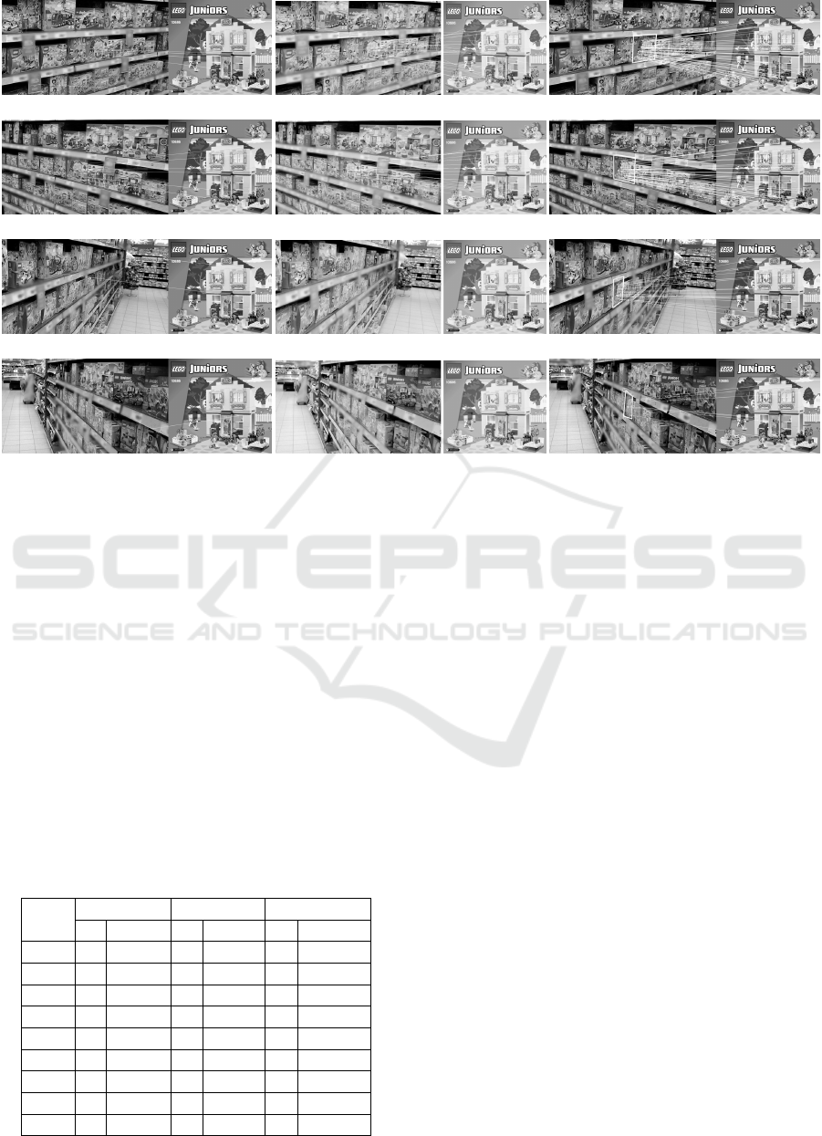
(a) SIFT (5/0,07%) (b) ASIFT (32/0,08%) (c) VIOL (82/17,52%)
(d) SIFT (6/0,09%) (e) ASIFT (26/0,06%) (f) VIOL (77/16,45%)
(g) SIFT (2/0,03%) (h) ASIFT (0/0,00%) (i) VIOL (19/4,06%)
(j) SIFT (1/0,01%) (k) ASIFT (0/0,00%) (l) VIOL (7/1,50%)
Figure 5: Typical examples from our object detection test set. This comparative overview illustrates that our system outper-
forms the existing approaches.
on the shelf lego and an arbitrarily chosen item. Fi-
gure 5 depicts some examples and Table 3 displays
the results. As shown in that table, that our approach
outperformed the existing approaches. For Φ u −70
◦
VIOL could not detect the correct 3D planar rec-
tangle and therefore did not produce any correspon-
dences. SIFT was unable to locate the desired item as
expected, due to the projective distortion introduced
through the given viewpoints. Although there were a
variety of false positives, we were unable to determine
valid correspondences using SIFT.
Table 3: Quantitative evaluation of shelf Lego. Here, we
want to detect a specific item within the shelf. VIOL out-
performs ASIFT and SIFT in terms of absolute and relative
feature correspondences. Again, VIOL was unable to detect
a valid plane in Φ u −70
◦
.
Φ
SIFT ASIFT VIOL
M R M R M R
−70
◦
5 0,07% 0 0,00% 0 0,0%
−60
◦
1 0,01% 0 0,00% 6 1,28%
−50
◦
2 0,00% 0 0,00% 19 4,06%
−45
◦
1 0,01% 0 0,00% 26 5,56%
−40
◦
3 0,04% 0 0,00% 26 5,56%
−30
◦
5 0,07% 32 0,08% 82 17,52%
30
◦
6 0,09% 26 0,06% 77 16,45%
40
◦
2 0,03% 0 0,00% 36 7,69%
50
◦
1 0,01% 0 0,00% 7 1,50%
ASIFT fails as well. This is because the available
version downscales input images to 800x600 pixels.
Then, it processes the images, samples different vie-
wpoints, and return the combination yielding the hig-
hest correspondences. Finally, it upscales the corre-
spondences to the size of the input images. This is
feasible as long as both input images are of the same
aspect ratio. However, if the approach is used to deter-
mine correspondences for two images with different
aspect ratios, this becomes erroneous. The descrip-
tors of two actually corresponding features differ due
to the different scaling in x and y direction. There-
fore, ASIFT was unable to determine corresponden-
ces for almost every sample in our test set, except for
Φ u −30
◦
and Φ u 30
◦
whereas the downscaled as-
pect ratios of the object and the object within the shelf
were similar.
5 CONCLUSION
In this paper, we proposed VIOL, a system to detect
objects within a supermarket. Therefore, we extended
a state-of-the-art feature matching framework. We de-
signed our system such that it detects different shelves
within a supermarket. Additionally, it tries to identify
objects within these shelves as soon as they come in
sight. We made use of the observation that man-made
VIOL: Viewpoint Invariant Object Localizator - Viewpoint Invariant Planar Features in Man-Made Environments
587

environments are rich of planar, rectangular structu-
res. Therefore, we relied on the sensors of Microsofts
HoloLens to detect 3D planes and determined view-
point invariant planes. Finally, we computed SIFT
features and determined correspondences using two
viewpoint invariant planes.
In the future, we plan to overcome issues while
detecting visible planes. As we have shown in our
evaluation, it possible that we discard planes using our
greedy selection approach. Additionally, we plan a
more extensive evaluation of the system.
REFERENCES
Baatz, G., K
¨
oser, K., Chen, D., Grzeszczuk, R., and Polle-
feys, M. (2010). Handling urban location recognition
as a 2D homothetic problem. In Computer Vision –
ECCV 2010, volume 6316, pages 266–279.
Bay, H., Ess, A., Tuytelaars, T., and Van Gool, L. (2008).
Speeded-Up Robust Features (SURF). Comput. Vis.
Image Underst., 110(3):346–359.
Brown, M. and Lowe, D. G. (2007). Automatic panora-
mic image stitching using invariant features. In Int. J.
Comput. Vis., volume 74, pages 59–73. Kluwer Aca-
demic Publishers-Plenum Publishers.
Cai, G. R., Jodoin, P. M., Li, S. Z., Wu, Y. D., Su, S. Z.,
and Huang, Z. K. (2013). Perspective-SIFT: An effi-
cient tool for low-altitude remote sensing image regis-
tration. Signal Processing, 93(11):3088–3110.
Chen, M., Shao, Z., Li, D., and Liu, J. (2013). Invariant
matching method for different viewpoint angle ima-
ges. Appl. Opt., 52(1):96–104.
Donoser, M., Riemenschneider, H., and Bischof, H. (2010).
Shape guided Maximally Stable Extremal Region
(MSER) tracking. In Proc. - Int. Conf. Pattern Re-
cognit., pages 1800–1803.
Filax, M., Gonschorek, T., and Ortmeier, F. (2017). Quad-
SIFT: Unwrapping planar quadrilaterals to enhance
feature matching. In WSCG 2017 - Short Papers Pro-
ceedings, volume 25.
Hartley, R. and Zisserman, A. (2004). Multiple View Ge-
ometry in Computer Vision. Cambridge University
Press.
K
¨
oser, K. and Koch, R. (2007). Perspectively invariant nor-
mal features. Proc. IEEE Int. Conf. Comput. Vis.
Lowe, D. G. (1999). Object recognition from local scale-
invariant features. In Proc. Seventh IEEE Int. Conf.
Comput. Vis., volume 2, pages 1150–1157. Ieee.
Lowe, D. G. (2004). Distinctive image features from scale-
invariant keypoints. International journal of computer
vision, 60(2):91–110.
Matas, J., Chum, O., Urban, M., and Pajdla, T. (2002). Ro-
bust Wide Baseline Stereo from. Br. Mach. Vis. Conf.,
pages 384–393.
Matas, J., Chum, O., Urban, M., and Pajdla, T. (2004).
Robust wide-baseline stereo from maximally sta-
ble extremal regions. Image and vision computing,
22(10):761–767.
McDonald, J. (2009). Viewpoint invariant features from
single images using 3D geometry. 2009 Work. Appl.
Comput. Vis., pages 1–6.
Morel, J.-M. and Yu, G. (2009). ASIFT: A New Framework
for Fully Affine Invariant Image Comparison. SIAM
J. Imaging Sci., 2(2):438–469.
Nister, D., Naroditsky, O., and Bergen, J. (2006). Visual
odometry for ground vehicle applications. J. F. Robot.,
23(1):3–20.
Rublee, E., Rabaud, V., Konolige, K., and Bradski, G.
(2011). ORB: An efficient alternative to SIFT or
SURF. In Proc. IEEE Int. Conf. Comput. Vis., pages
2564–2571. IEEE.
Srajer, F., Schwing, A. G., Pollefeys, M., and Pajdla, T.
(2015). MatchBox: Indoor image matching via box-
like scene estimation. In Proc. - 2014 Int. Conf. 3D
Vision, 3DV 2014, pages 705–712.
Wu, C., Clipp, B., Li, X., Frahm, J. M., and Pollefeys, M.
(2008). 3D model matching with viewpoint-invariant
patches (VIP). 26th IEEE Conf. Comput. Vis. Pattern
Recognition, CVPR, pages 1–8.
Yu, G. and Morel, J. (2009). A fully affine invariant image
comparison method. Int. Conf. Acoust. Speech Signal
Process., 26(1):1597–1600.
Yu, G. and Morel, J.-M. (2011). ASIFT: An Algorithm for
Fully Affine Invariant Comparison. Image Processing
On Line, 1:11–38.
Yu, Y., Member, S. S., Huang, K., Member, S. S., Chen, W.,
Member, S. S., and Tan, T. (2012). A novel algorithm
for view and illumination invariant image matching.
IEEE Trans. Image Process., 21(1):229–40.
Yuille, A. L. and Coughlan, J. M. (2000). The Manhat-
tan World Assumption: Regularities in scene satistic
which enable Bayesian inference. NIPS - Neural Inf.
Process. Syst., pages 2–8.
VISAPP 2018 - International Conference on Computer Vision Theory and Applications
588
