
PEAR: Prototyping Expressive Animated Robots
A Framework for Social Robot Prototyping
Etienne Balit, Dominique Vaufreydaz and Patrick Reignier
Inria - LIG - Université Grenoble Alpes, Grenoble, France
Keywords:
Robot Animation, Robot Prototyping Tool, Social Robot, Expressive Robot, Animation Software, Blender.
Abstract:
Social robots are transitioning from lab experiments to commercial products, creating new needs for pro-
totyping and design tools. In this paper, we present a framework to facilitate the prototyping of expressive
animated robots. For this, we start by reviewing the design of existing social robots in order to define a set of
basic components of social robots. We then show how to extend an existing 3D animation software to enable
the animation of these components. By composing those basic components, robots of various morphologies
can be prototyped and animated. We show the capabilities of the presented framework through 2 case studies.
1 INTRODUCTION
As social robots get out of the labs and into homes,
taking on new tasks and roles, the question of these
robots user experience become more salient. Much of
the user experience of a social is related to its appea-
rance and how it moves. Designing appearance can
be used to set expectations about the robot capabi-
lities (Duffy, 2003) while designing movements can
improve the legibility of the robot intentions (Taka-
yama et al., 2011). Therefore these two dimensions
are major in the design of a social robot. Designing
the appearance and movements independently can be
limited because the possible movements depend on
the shape of the robot and its actuators.
(Hoffman and Ju, 2014) suggest a methodology
focusing on the movement design. In a first phase,
they use paper sketches to define the robot appea-
rance, as a cartoonist would do to find the design of
a character, and rough 3D shapes animation to define
the robot’s way of moving. It allows them to iterate
rapidly between the design of the robot appearance
and its movements. However, animating robots rai-
ses additional challenges compared to 3D animation.
Robots are subject to the laws of physics. They can
oscillate, shake or vibrate and their motors produce
friction-related noise. In addition, their engines have
speed and acceleration limits. These constraints spe-
cific to robot animation can modify the expressiveness
of a movement if they are not taken into account. In
(Hoffman and Ju, 2014), these constraints are taken
into account in a second phase consisting in the fabri-
cation of skeleton prototype of the robot. This step
also requires the creation of a dedicated software to
animate the prototype. We are proposing in this work
a simplified system for this step.
The design of robot animation software has been
explored in previous work (Van Breemen and Xue,
2006) (Pot et al., 2009) (Saldien et al., 2014), each
time for a specific robot. A common factor is their
use of concepts from 3D animation tools. Those con-
cepts have the advantage of being already familiar to
animators. We propose to go further in the familiarity
and to extend an existing 3D animation software to
animate the robots prototypes. Animation tools have
a steep learning curve and reusing one that animators
already master will make the system easier to adopt.
A second advantage is that it can be used to evaluate
how well different parts of 3D animation tools trans-
fer to robotics.
Our objective is to design a general system allo-
wing different robot morphologies to be prototyped
and animated. We propose to do so by defining a set
of common basic components that can be assembled
together to compose different morphologies.
In section 2, we present an overview of the ex-
isting social robots design landscape. In section 3,
we define categories of basic components shared by
those robots. In section 4, we present the 3D anima-
tion software Blender and an overview of its features.
In section 5, we describe how our system map Blen-
der features to animate different components catego-
ries. Finally, in section 6, we present 2 case studies of
robots animated thanks to our system.
44
Balit, E., Vaufreydaz, D. and Reignier, P.
PEAR: Prototyping Expressive Animated Robots - A Framework for Social Robot Prototyping.
DOI: 10.5220/0006622600440054
In Proceedings of the 13th International Joint Conference on Computer Vision, Imaging and Computer Graphics Theory and Applications (VISIGRAPP 2018) - Volume 2: HUCAPP, pages
44-54
ISBN: 978-989-758-288-2
Copyright © 2018 by SCITEPRESS – Science and Technology Publications, Lda. All rights reserved
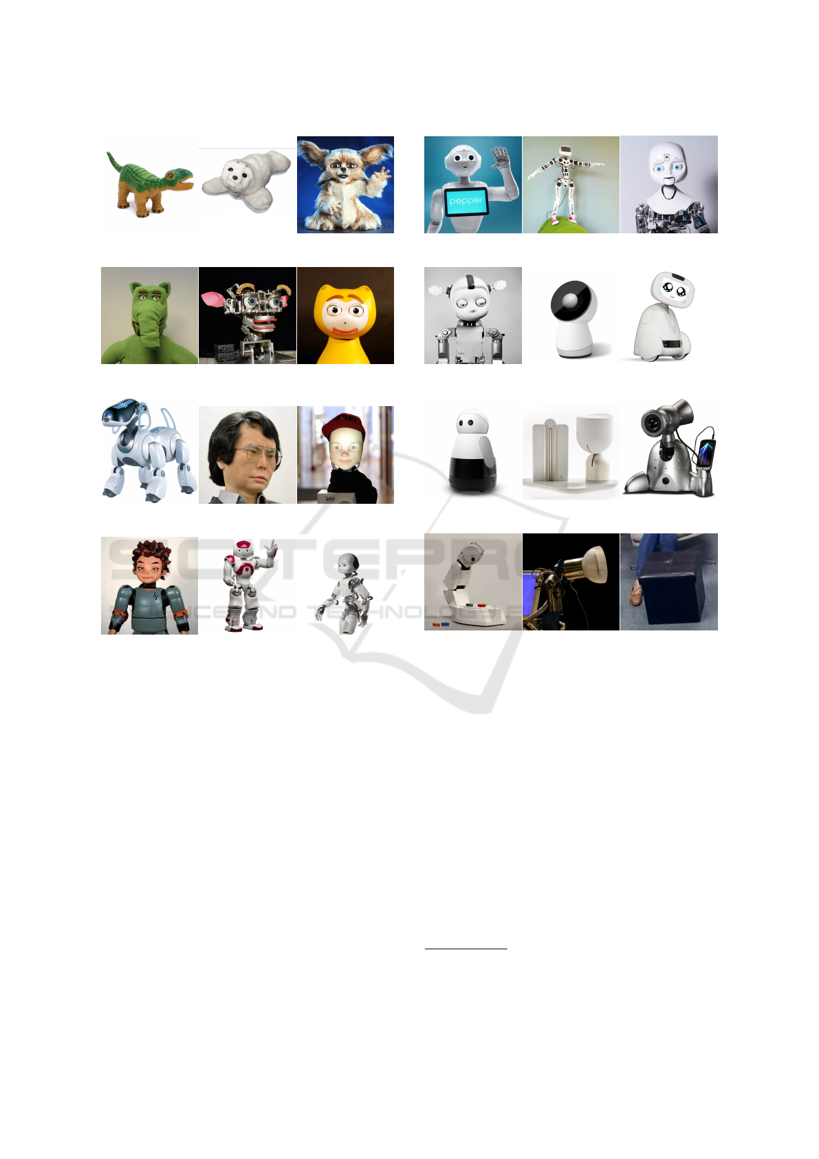
(a) Pleo (b) PaRo (c) Leonardo
(d) Probo (e) Kismet (f) iCat
(g) Aibo (h) Geminoid (i) Furhat
(j) Zeno (k) NAO (l) iCub
Figure 1: Examples of social robots.
2 SOCIAL ROBOTS
Social robots are designed to be able to express social
behaviours to communicate with their users. Their
designs vary greatly according to their roles, but also
because of the aesthetic and technical choices of their
designers. Examples of social robots are shown in fi-
gures 1 and 2. We class them along 3 dimensions:
appearance, morphology and facial expressions im-
plementation.
2.1 Appearance
Some designers choose to endow their robot with a
human or humanoid form, with different degrees of
realism. Geminoid (Nishio et al., 2007) and Fur-
hat (Al Moubayed et al., 2012) are designed to get
as close as possible to the human appearance, while
(a) Pepper (b) Poppy (c) Nexi
(d) Simon (e) Jibo (f) Buddy
(g) Kuri (h) ElliQ (i) Travis
(j) Vyo (k) AUR (l) Mechanical Ot-
toman
Figure 2: Examples of social robots (cont.).
Zeno (Hanson et al., 2009) takes inspiration from
manga characters. Conversely, other robots such as
Nexi (Fitzpatrick, 2012), iCub (Beira et al., 2006),
Simon (Chao et al., 2010), Pepper
1
, NAO (Gouaillier
et al., 2009) and Poppy (Lapeyre et al., 2014) have
forms inspired by humans but without aiming for rea-
lism.
The animal form is also widely used, sometimes
inspired by imaginary animals. Pleo
2
takes the shape
and appearance of a dinosaur while PaRo (Shibata
et al., 1997) is inspired by a seal. Probo (Saldien
et al., 2008), Leonardo (Brooks et al., 2004) or Kis-
met (Breazeal and Scassellati, 1999) have an animal-
like appearance without one being able to define the
animals they resemble. Finally, Aibo (Fujita, 2001)
1
https://www.ald.softbankrobotics.com/en/robots/
pepper/find-out-more-about-pepper
2
http://www.pleoworld.com
PEAR: Prototyping Expressive Animated Robots - A Framework for Social Robot Prototyping
45
or iCat (van Breemen et al., 2005) have a form inspi-
red by animals that can be clearly defined but with a
cartoonish appearance.
Other designers break free more or less strongly
from human or animal forms and appearances. Some
robots such as Buddy
3
or Kuri
4
retain a shape with a
head and eyes. Others such as Jibo
5
, Travis (Hoffman,
2012) or ElliQ
6
retain only a head-like shape. Finally,
others such as the Vyo (Luria et al., 2016) abstracted
even more strongly from animal forms by adopting a
form closer to a household appliance. Despite this ab-
straction effort, its shape remains evocative of a head.
Finally, some designers uses furniture shape. For
instance, AUR (Hoffman et al., 2007) takes the form
of a lamp while the Mechanical Ottoman (Sirkin et al.,
2015) is an actual footrest that has been robotized.
2.2 Morphology
Social robots can also be classified according to their
morphology and more particularly their controllable
morphology, thus ignoring the parts of their "body"
that are only aesthetic. As we have seen for appea-
rance, it can be difficult to avoid animal vocabulary to
talk about the form of social robots. We will use this
vocabulary for our morphology classification.
A first category groups together the robotic heads,
which consist essentially of a head and neck. This
category includes precursors such as Kismet or iCat,
but also the more recent ones such as Furhat, Jibo or
ElliQ and Vyo. Travis robot can also be classified in
this category, although it has a mechanized foot and
smartphone mount.
A second category includes robotic torsos equip-
ped with a torso and arms. Probo, Leonardo and
Geminoid robots are in this category. Some huma-
noid robots such as Zeno, Poppy or NAO also exist in
"torso" versions restricted to the upper body.
Some robots can be classed as mobile variant of
those two categories. Kuri and Buddy can thus be
considered mobile robotic heads, while Nexi, Simon
and Pepper can be considered mobile robotic torso,
although they are most often defined as wheeled hu-
manoids.
A final category includes robots with a complete
"body", either bipedal like iCub, NAO, Poppy and
Zeno, or quadruped like Aibo and Pleo.
3
http://www.bluefrogrobotics.com/en/buddy/
4
https://www.heykuri.com/explore-your-home-robot
5
https://www.jibo.com/
6
https://www.intuitionrobotics.com/elliq
2.3 Facial Expressions
The last axis to classify social robots is the choice
of implementing facial expressions, given the impor-
tance of the face for a social robot. Some robots such
as PaRo, Travis, ElliQ and Vyo have no facial expres-
sions. NAO, Pepper and Aibo are also minimalist in
this area as they have only a few LEDs that do not al-
low facial expressions to be represented as such. iCub
is equipped with LED panels to define the shape of
its eyebrows and mouth. Other robots like Jibo and
Buddy use a screen for this purpose. Furhat also uses
a screen but retro-projected on a face shape. Finally,
some robots have an articulated face. It is the most re-
presented category among the robots described above
with Leonardo, Kismet, Probo, Zeno, Nexi, Simon
and Geminoid.
3 EXPRESSIVE ROBOTS
COMPONENTS
Our analysis of the different social robots reveals si-
milarities in actuators used for expressive purposes.
We define 4 categories of actuators: main and secon-
dary motors (dynamic actuators), screens and LEDs
(static actuators).
3.1 Dynamic Actuators
Main Motors. The main motors have as their pri-
mary role the movement of the robot joints. They
most often have to be able to provide an important tor-
que, so that they can move the attached parts of the ro-
bot. The motors of a humanoid robot’s shoulder must
therefore have enough torque to carry its arm, those
of the elbow its forearm and those of the wrist only
its hand. Their functional importance means that the
vast majority of social robots are equipped with them.
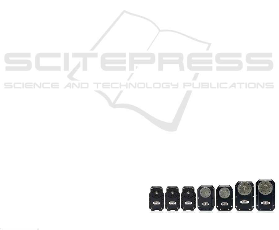
The range of Robotis Dynamixel motors presented in
figure 3 is often used in the prototyping phase for this
type of actuators.
Figure 3: Dynamixel servomotors line from Robotis.
Secondary Motors. Secondary motors have mainly
an expressive function and are often used for the mo-
vements of the elements of robots face and hands.
They generally do not need to provide a significant
HUCAPP 2018 - International Conference on Human Computer Interaction Theory and Applications
46
couple. In most cases, they do not need to be very pre-
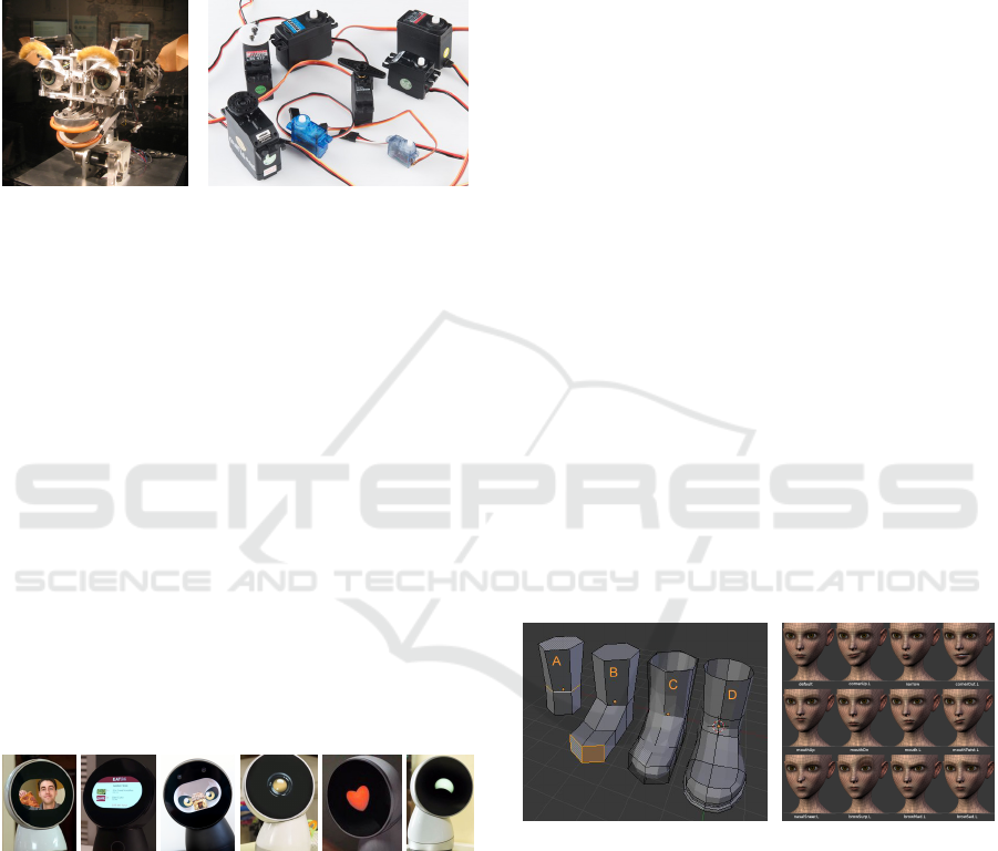
cise either. Kismet (figure 4) is an example of a robot
whose facial expressions are generated by 15 secon-
dary motors. Radio-controlled vehicle actuators, so-
metimes called hobby servos, are generally used for
this purpose during the prototyping phase. Figure 5
shows some examples of this type of motors.
Figure 4: Kismet. Figure 5: Examples of RC
servomotors.
3.2 Static Actuators
Screens. In recent years, usage of screens as com-
ponents of social robots has increased. Indeed,
screens can represent facial expressions without the
mechanical complexity that is required to generate fa-
cial expressions using motors. They also have the ad-
vantage of being very flexible and can display facial
expressions, iconography or even more classic graphi-
cal user interfaces. In addition, the cost of screens has
dropped sharply with the democratization of smartp-
hones and tablets. The Jibo robot is probably the first
robot to adopt the screen as its main actuator. Fi-
gure 6 illustrates the different types of uses of the Jibo
screen. The Pepper robot also uses a screen, positio-
ned on its chest in this case, whose main function is
to display a graphical user interface but which is so-
metimes used for expressive purposes.
Figure 6: Different functions of Jibo’s screen. From left
to right, Jibo’s screen is used to display the stream of a vi-
deoconference, a graphical user interface, an illustration of
children’s story, an icon indicating the current application,
an icon expressing an emotion and a facial expression.
LEDs. LEDs are used as expressive actuators in two
ways. The first is to use LEDs to represent anthro-
pomorphic facial expressions. For example, the iCub
robot is equipped with LED panels to define the shape
of its eyebrows and mouth. The second is to use them
to display a color representing an emotion or state of
the robot. The Simon robot is equipped with ears il-
luminated by controllable LEDs. These two uses are
not exclusive, the same LEDs can be used for both, as
for the LEDs around the eyes of the NAO and Pepper
robots, which are sometimes used to indicate an emo-
tion by varying their color but also to represent a kind
of blink of the eyes. LEDs can also be seen as very
low-resolution displays.
4 OVERVIEW OF BLENDER
FEATURES
The prototyping tool we present is based on Blender, a
professional open-source 3D creation software. Blen-
der’s featureset is very broad, with features ranging
from 3D modelling to video editing and animation.
We will present the different feature that are proposed
by Blender to animate 3D characters and the exten-
sion capabilities that it offers.
4.1 Defining Shapes
Geometric Modelling. Blender provides many
tools to model objects or characters in 3D. The ge-
neral principle is to model these forms as meshes. A
mesh is an approximation of a surface by triangular or
quadrilateral facets. Each face is defined by its verti-
ces and edges. A shape is modeled by starting from a
basic (or primitive) mesh and moving, dividing or re-
moving its vertices, edges and faces, in order to sculpt
it until the desired shape is obtained as shown in fi-
gure 7.
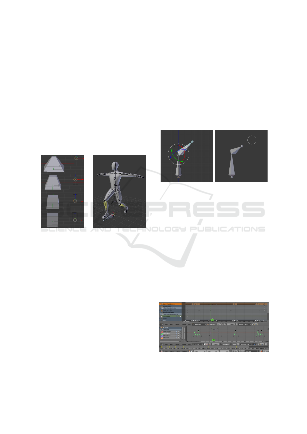
Figure 7: Modelling of a
boot in Blender.
Figure 8: 12 examples
of shape keys for Sintel’s
character.
Blend Shapes. In order to animate deformations of
objects or characters, Blender provides shape inter-
polation features. This works by creating variants of
the same mesh called shape keys and interpolating
them with variable weights to obtain a blend shape of
the different deformations. An important constraint is
that these variants must retain the same vertices, ed-
ges and faces, because the mesh topology should to be
identical in order to be able to interpolate them. This
allows for example to have several variations of a cha-
racter’s face with different expressions and to animate
PEAR: Prototyping Expressive Animated Robots - A Framework for Social Robot Prototyping
47
its emotions by modulating the weights of these vari-
ants. Figure 8 shows examples of shape keys desig-
ned to animate the Sintel character in the eponymous
animated short film of the Blender Foundation.
Shape Drivers. Controlling shape interpolation
quickly becomes complicated by limiting itself to the
shape keys weight interface. Blender allows you to
create drivers, i. e. virtual objects whose position
is associated with the weights of one or more shape
keys. Animating these virtual objects then means
animating the weights of the shape keys attached to
them, thus animating the deformation of the shape it-
self. This feature allows animators to create their own
graphical control interface to define a blend shape. Fi-
gure 9 shows an example of shape interpolation con-
trolled through a shape driver.
Figure 9: Example of a
shape driver.
Figure 10: Example of an
armature.
4.2 Defining Poses
Armatures are another means proposed by Blender to
control the deformation of a mesh or set of meshes. A
framework can be seen as the skeleton of a character.
It is composed of one or more hierarchically organi-
zed bones to which meshes can be attached. The lat-
ter will then follow the movements and deformations
of this bone. The movements and deformations of a
bone can be constrained according to the desired mo-
vements of the character. A first constraint that may
be desired is to force the bone to keep the same length,
thus limiting its movements to a rotation. It may also
be desired to freeze one or more rotations. An elbow
bone could be forced to have only one degree of free-
dom. Finally, you may wish to limit the rotation over
a given interval, thus defining a minimum angle and
a maximum angle. An armature pose can be modi-
fied in two ways: by forward kinematics or by inverse
kinematics.
Forward Kinematics. The forward kinematics
method consists of directly modifying the angle be-
tween a bone and its parent. This method gives pre-
cise control but can quickly become tedious when the
number of bones increases.
Inverse Kinematics. The inverse kinematics met-
hod involves defining targets that a bone will try to re-
ach. Blender then uses an inverse kinematic engine to
find the armature pose which minimizes the distance
between the bone and the target while respecting the
constraints of the armature.
(a) Forward kinematics (b) Inverse kinematics
Figure 11: Comparison of forward and inverse kinematics
for defining an armature pose.
4.3 Keyframes Animation
Animation in Blender is based on the principle of
keyframes. A keyframe is a record of the value of
a parameter at a given point in an animation. In Blen-
der, all parameters can be animated, such as the ob-
jects position, characters poses or the different shape
keys’ weights. To animate an action, the anima-
tor starts by defining keyframes of the animation by
choosing the parameters to be recorded and when to
do so. These keyframes can then be shifted in time
on the dope sheet to fine-tune the animation timing.
Finally, the speed profile of the transition from one
keyframe to the next can be defined using the F-curve
editor.
Figure 12: Keyframes animation interface in Blender. The
top part shows the dope-sheet and the bottom part the F-
curve editor.
HUCAPP 2018 - International Conference on Human Computer Interaction Theory and Applications
48

4.4 Python API
Blender’s features can be extended with the integrated
Python interpreter. The API offers many possibilities.
First, it provides reading and writing access to Blen-
der’s data structures, allowing for example to retrieve
an object’s position. It also allows to attach functions
to Blender’s event system. Finally, it allows to add
elements to the Blender’s user interface.
5 OVERVIEW OF OUR SYSTEM
We have previously presented the different categories
of components commonly used for expressive purpo-
ses in Social Robotics, as well as Blender’s various
modeling, animation and extensibility features. Here
we describe how we use Blender’s features to imple-
ment an animation system for each component cate-
gory.
5.1 Mapping Actuators to Blender’s
Features
The general principle of our system is to transpose the
state of an animated virtual object in Blender to actu-
ators on the real robot. The control of the different
categories of actuators can be divided into two groups
according to the principle of operation: motors ani-
mation and screens animation.
5.1.1 Motors Animation
Among Blender’s features, we have introduced the
shapes drivers, virtual objects whose positions drive
shape keys’ weights. Our system uses the driver con-
cept to control the position of the main and secondary
motors, i. e. the position or angle of an animated
virtual object in Blender drives the angle of a physi-
cal motor. Two types of motor drivers can be used:
armatures and control rigs.
Armatures. As we have seen before, the armatures
allow Blender to define the skeleton of a character.
In our case, they are a natural solution to control the
robot’s main motors. An armature can be defined in
Blender to model the kinematic chain(s) of the robot,
each bone representing a motor and its constraints, i.
e. the axis of rotation and the minimum and maximum
angle. Thanks to Blender’s inverse kinematics featu-
res described above, it is also possible to define targets
for certain armature bones. This allows to control its
pose by directly manipulating these targets. For in-
stance, mapping the x angle of the l_elbow bone and
a main motor (Dynamixel) of id 12 is done by adding
these few lines to the mapping file:
{
’from’: {
’path’: ’l_elbow/angle/x’,
’min’: 0,
’max’: 90
},
’to’: {
’path’: ’Dynamixel/12’,
’min’: -90,
’max’: 0
}
}
Allowing a transformation between the bone and the
motor angles allows more flexibility in setting up the
mapping. We choose to use a linear transformation
from the bone angle range to the motor angle range,
defined by their respective minimum and maximum
angles. This method of configuring the mapping is
intuitive as it is easy to find those minimum and max-
imum angles and to visualize the linear transforma-
tion.
Control Rig. We have previously presented Blen-
der’s features to enable the user to define a custom
graphical interface also called control rig for control-
ling the weights of different shape keys. Similarly,
our system allows to retrieve a virtual object position
to control a motor angle. For example, the animator
can create a slider by defining a virtual object con-
strainted on a given range on the x axis and fixed on
the y and z axis. Control rigs are useful for control-
ling secondary motors. For example, mapping the x
position of a virtual objet ears_slider and a secon-
dary motor (or hobby) of id 6 is done by adding these
few lines to the mapping file:
{
’from’: {
’path’: ’ears_slider/position/x’,
’min’: 0,
’max’: 90
},
’to’: {
’path’: ’Hobby/6’,
’min’: 0,
’max’: 90
}
}
5.1.2 Screens Animation
In our system, we use smartphone or tablet as off-the-
shelf screens. We render the meshes that would be
PEAR: Prototyping Expressive Animated Robots - A Framework for Social Robot Prototyping
49
captured by a Blender virtual camera on the smartp-
hone or tablet. This allows the animator to use all mo-
deling and shape interpolation features provided by
Blender to animate facial expressions, iconography or
text. Mapping the virtual camera face_camera and
the screen of id 1 correspond to adding these line to
the mapping file:
{
’from’: {
’path’: ’face_camera’
},
’to’: {
’path’: ’Screen/1’
}
}
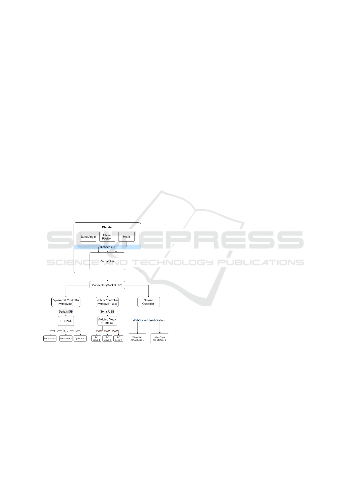
5.2 Architecture
Figure 13 presents the architecture of our system im-
plementing the synchronization of each actuator with
the corresponding virtual object animated in Blender.
The architecture can be broken down into two parts:
the dispatcher that communicates with Blender, and
the controllers that communicate with the actuators.
Figure 13: Diagram of our system architecture.
5.2.1 Dispatcher
The dispatcher is the main component of our system.
Its operation is controlled by the mapping file descri-
bed above which defines the associations between vir-
tual objects and actuators. Virtual objects and actua-
tors are represented by an address. The source address
contains the name of the virtual object and the attri-
bute of interest. The destination address is the name
of the controller that should receive the information
followed by an actuator identifier. The association can
also contain a transformation to be made on the value
of the attribute before sending it to the controller.
The dispatcher is plugged into Blender’s event sy-
stem by attaching itself as a callback function to the
scene_update_post event. Each time Blender up-
dates, the dispatcher checks whether the virtual scene
has been modified, i. e. whether a virtual object has
been moved, either by the user or by Blender’s ani-
mation engine.
If so, the dispatcher processes each association
defined in the mapping file: it retrieves the informa-
tion defined by the source address and transmits it
to the controller indicated by the destination address,
along with the destination actuator identifier. If the
source virtual object is a camera, the transmitted in-
formation contains the camera settings and the scene
meshes. Otherwise, it contains the value of the attri-
bute of interest as defined in the source address.
5.2.2 Controllers
A controller operates all actuators of the same type.
Those actuators are differentiated within one control-
ler by a unique identifier. These are the identifiers that
can be found in the destination addresses of the map-
ping file. Controllers are independent processes with
which the dispatcher communicates asynchronously
through an inter-process communication socket that
we will call the connector. We use the implementa-
tion of the Publish-Subscribe communication pattern
of the ZeroMQ library. The controller name contained
in the destination address corresponds to the subto-
pic topic on which the information will be published
by the dispatcher. This choice of architecture allows
new actuators to be integrated into the system by ad-
ding controllers. All you need to do is choose a topic
identifier and use it in a destination address. The new
controller will then only have to subscribe to the topic
to join the system.
For example, to add LEDs control to the system,
we could use the fact that LEDs and especially LED
panels can be thought of as low resolution screens.
First, we would need to create an association between
a virtual camera and a destination address beginning
with the topic LED by adding the following lines to the
mapping file:
{
’from’: {
’path’: ’leds_camera’
},
’to’: {
’path’: ’LED/1’
}
}
HUCAPP 2018 - International Conference on Human Computer Interaction Theory and Applications
50
We would then be able to subscribe a LED controller
to the LED topic through the socket connector.
In our implementation, subscription has the par-
ticularity of being "lazy", i. e. it corresponds to re-
trieving only the last message published on the topic.
In this way, the latest information can be used to li-
mit latency between Blender and actuators. This is
possible because we chose to directly send absolute
values from Blender to the controllers and to control
the motors in position.
The system integrates 3 controllers: Dynamixel
for Robotis Dynamixel motors, Hobby for RC servo
motors and Screen for screens.
Dynamixel Controller. Robotis Dynamixel mo-
tors are often used in social robotics during the pro-
totyping phase. They are digital actuators with TTL
half-duplex interface. We use a USB2AX board and
the PyPot library developed as part of the Poppy pro-
ject (Lapeyre et al., 2014) to control the motors.
Hobby Controller. RC servomotors must be con-
trolled by a PWM signal (for Pulse Width Modula-
tion) encoding a target angle. We use an Arduino
MEGA board to generate this signal using the Servo
library included in the standard Arduino distribution.
In order to directly control the signal generated by the
board from the controller written in Python, we use
firmata on the Arduino, a firmware allowing to cont-
rol the features of the board remotely, and the library
pyfirmata on the Python side. The communication be-
tween the Arduino board and the controller is done via
a USB connection.
Screen Controller. We use Android smartphones
as screens (and potentially tablets). They run a web
application connected to the Screen controller via
WebSocket. This application is responsible for ren-
dering the scene 3D thanks to the camera parameters
and the scene meshes transmitted by the controller. It
uses the library Three.js, a Javascript library to cre-
ate and render 3D scenes thanks to the WebGL API.
The rendering is therefore not done by Blender but
directly by the browser on the phone.
6 CASE STUDIES
In order to experiment and validate this prototyping
system of animated robots, we applied it to the ani-
mation of two examples of social robots: Mia, a robot
we designed specifically for this purpose, and Poppy,
an existing open-source robot.
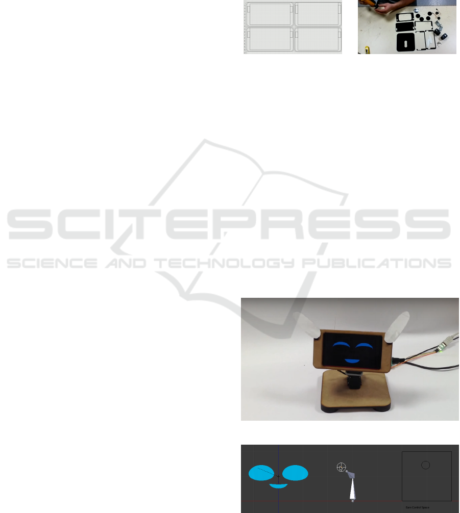
6.1 Mia
We designed the Mia robot as an example of the deve-
loped system (figure 14). It is equipped with 3 types
of actuators that we have identified as frequently used
in social robotics, i. e. main motors, secondary mo-
tors and screens.
(a) Screenshot of Mia’s
structure design.
(b) Screenshot of Mia’s as-
sembly (in a plexiglass ver-
sion).
Figure 14: Design and assembly of Mia.
Mia has 4 degrees of freedom, 2 main motors for
the neck and 1 secondary motor per ear. The neck is
powered by Robotis Dynamixel AX12A servomotors
while each ear uses a RC servomotor. The structure
is designed from parts included with the Dynamixel
motors and parts laser cut in wood fibreboard panels
(MDF). On Blender’s side, the 2 Dynamixel actua-
tors are controlled by an armature which takes up the
geometric structure of the neck and the 2 RC servo-
motors of its ears are controlled by a 2D slider (fi-
gure 16).
Mia also comes with a screen displaying 2 eyes
and a mouth. The eyes are blend shapes of the initial
eye shape and 4 shape keys (figure 17) whose weights
are controlled in Blender thanks to 4 sliders.
Figure 15: Mia presentation.
Figure 16: Mia control rig.
PEAR: Prototyping Expressive Animated Robots - A Framework for Social Robot Prototyping
51
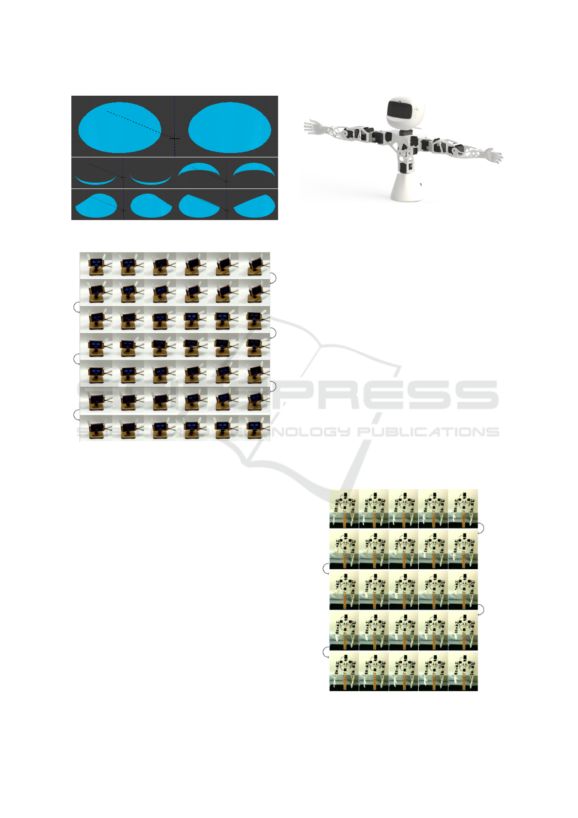
Figure 17: Basic shape (top) and shape keys (bottom) for
Mia eyes.
Figure 18: Example animation of Mia. The corre-
sponding video is available at the following address:
https://youtu.be/aQ-g0b3mRRo.
Observations and Discussion
Mia can easily be animated with this system. The
physical robot allows an immediate feedback. The
movement is performed with all the speed or acce-
leration constraints of the robot as well as the motor
generated sound. This feedback makes it possible to
quickly judge the final result, and in particular to ve-
rify that the movement keeps the desired style.
6.2 Poppy
Poppy is an open-source robot (Lapeyre et al., 2014)
developped by the Flowers team at Inria Bordeaux.
Initially designed as an experimental platform to
study the acquisition of walking by children, it has
since then been used in multiple artistic performan-
ces, as educational platform or as compagnon robot
for hospitalized children.
Figure 19: Poppy Torso presentation.
We use Poppy torso version. It has 13 degrees of
freedom: 2 for the neck, 3 for the bust and 4 for each
arm. These are all powered by Robotis Dynamixel
MX28AT servomotors, except for the neck which uses
AX12A servomotors from the same line. On Blender’s
side, the robot motors are controlled by an armature
that takes up the geometrical structure of the real ro-
bot.
Observations and Discussion
Although Poppy can be animated thanks to this sy-
stem, new difficulties are encountered due to the high
number of degrees of freedom of the robot. First, in-
verse kinematics must be used to define the robot’s
pose, directly controlling the angles becoming tedi-
ous. The robot could potentially be used as a tangi-
ble interface to directly define the robot pose instead
of relying on inverse kinematics. Secondly, the vir-
tual robot must be handled with care to avoid self-
collisions on the real robot. A collision detection me-
chanism could avoid putting this task and the associ-
ated cognitive burden on the user.
Figure 20: Example animation of the Poppy robot.
HUCAPP 2018 - International Conference on Human Computer Interaction Theory and Applications
52

7 CONCLUSIONS
The PEAR framework presented in this paper aims
to respond to the rising need for prototyping and de-
sign tools associated with the emergence of the social
robots market. We showed that existing social robots
share common basic components and how those com-
ponents can be animated using 3D animation tools
and methods. This enables the rapid prototyping of
expressive animated robots as we have shown with
the prototyping of the Mia robot. We also showed
how this framework can be used to easily create an
animation tool for an existing robot, using Poppy as
an example.
Case studies also raised some limitations of the
current system. Animating a robot by mapping the
state of virtual objects onto its actuators works very
well for simple robots like Mia, with few degrees of
freedom and no possibilities of self-collision. Howe-
ver, more complex robots like Poppy would benefit
from features managing the robot physical constraints
for the user. (Nakaoka, 2012) showed for example an
animation tool integrating an automated balancing of
the robot. Our system could also be improved through
better input modalities. In our previous work (Balit
et al., 2016), we showed how a robot can be used as
a tangible interface for defining poses, thus avoinding
the reliance on inverse kinematics. We are looking
into ways of integrating those features to the presen-
ted system.
We believe that fostering a design community will
be essential for the developpement of social robots.
Having a common prototyping tool would be an im-
portant step in this direction. 3D animation tools have
large communities of animators and character desig-
ners whose skills could grealty improve the user ex-
perience of social robots. Our work extending a 3D
animation tools for robot prototyping is a first step
towards building a bridge between those artists and
social robots design.
ACKNOWLEDGEMENTS
This work was partly funded by the Agence
Nationale de la Recherche (ANR) under the project
Amiqual4Home ANR-11-EQPX-0002.
REFERENCES
Al Moubayed, S., Beskow, J., Skantze, G., and Granström,
B. (2012). Furhat: a back-projected human-like robot
head for multiparty human-machine interaction. Cog-
nitive behavioural systems, pages 114–130.
Balit, E., Vaufreydaz, D., and Reignier, P. (2016). Integra-
ting animation artists into the animation design of so-
cial robots: An open-source robot animation software.
In The Eleventh ACM/IEEE International Conference
on Human Robot Interaction, pages 417–418. IEEE
Press.
Beira, R., Lopes, M., Praça, M., Santos-Victor, J., Ber-
nardino, A., Metta, G., Becchi, F., and Saltarén, R.
(2006). Design of the robot-cub (icub) head. In Robo-
tics and Automation, 2006. ICRA 2006. Proceedings
2006 IEEE International Conference on, pages 94–
100. IEEE.
Breazeal, C. and Scassellati, B. (1999). How to build ro-
bots that make friends and influence people. In In-
telligent Robots and Systems, 1999. IROS’99. Procee-
dings. 1999 IEEE/RSJ International Conference on,
volume 2, pages 858–863. IEEE.
Brooks, A. G., Gray, J., Hoffman, G., Lockerd, A., Lee,
H., and Breazeal, C. (2004). Robot’s play: interactive
games with sociable machines. Computers in Enter-
tainment (CIE), 2(3):10–10.
Chao, C., Gielniak, M., Yoo, J. W., and Thomaz, A. L.
(2010). Interactive learning by demonstration with the
simon robot. In Proceedings of the 9th AAAI Confe-
rence on Enabling Intelligence Through Middleware,
pages 2–2. AAAI Press.
Duffy, B. R. (2003). Anthropomorphism and the social ro-
bot. Robotics and Autonomous Systems, 42(3):177 –
190. Socially Interactive Robots.
Fitzpatrick, R. J. (2012). Designing and constructing an
animatronic head capable of human motion program-
med using face-tracking software. PhD thesis, Wor-
cester Polytechnic Institute.
Fujita, M. (2001). Aibo: Toward the era of digital creatu-
res. The International Journal of Robotics Research,
20(10):781–794.
Gouaillier, D., Hugel, V., Blazevic, P., Kilner, C., Mon-
ceaux, J., Lafourcade, P., Marnier, B., Serre, J., and
Maisonnier, B. (2009). Mechatronic design of nao hu-
manoid. In Robotics and Automation, 2009. ICRA’09.
IEEE International Conference on, pages 769–774.
IEEE.
Hanson, D., Baurmann, S., Riccio, T., Margolin, R.,
Dockins, T., Tavares, M., and Carpenter, K. (2009).
Zeno: A cognitive character. In Ai magazine, and spe-
cial proc. of aaai national conference, chicago.
Hoffman, G. (2012). Dumb robots, smart phones: A case
study of music listening companionship. In RO-MAN,
2012 IEEE, pages 358–363. IEEE.
Hoffman, G. et al. (2007). Ensemble: fluency and embo-
diment for robots acting with humans. PhD thesis,
Massachusetts Institute of Technology.
Hoffman, G. and Ju, W. (2014). Designing robots with mo-
vement in mind. Journal of Human-Robot Interaction,
3(1):89–122.
Lapeyre, M., Rouanet, P., Grizou, J., Nguyen, S., Depraetre,
F., Le Falher, A., and Oudeyer, P.-Y. (2014). Poppy
PEAR: Prototyping Expressive Animated Robots - A Framework for Social Robot Prototyping
53

project: Open-source fabrication of 3d printed huma-
noid robot for science, education and art. In Digital
Intelligence 2014, page 6.
Luria, M., Hoffman, G., Megidish, B., Zuckerman, O., and
Park, S. (2016). Designing vyo, a robotic smart home
assistant: Bridging the gap between device and social
agent. In Robot and Human Interactive Communica-
tion (RO-MAN), 2016 25th IEEE International Sym-
posium on, pages 1019–1025. IEEE.
Nakaoka, S. (2012). Choreonoid: Extensible virtual robot
environment built on an integrated gui framework. In
System Integration (SII), 2012 IEEE/SICE Internatio-
nal Symposium on, pages 79–85. IEEE.
Nishio, S., Ishiguro, H., and Hagita, N. (2007). Geminoid:
Teleoperated android of an existing person. In Huma-
noid robots: new developments. InTech.
Pot, E., Monceaux, J., Gelin, R., and Maisonnier, B. (2009).
Choregraphe: a graphical tool for humanoid robot
programming. In Robot and Human Interactive Com-
munication, 2009. RO-MAN 2009. The 18th IEEE In-
ternational Symposium on, pages 46–51. IEEE.
Saldien, J., Goris, K., Yilmazyildiz, S., Verhelst, W., and
Lefeber, D. (2008). On the design of the huggable
robot probo.
Saldien, J., Vanderborght, B., Goris, K., Van Damme, M.,
and Lefeber, D. (2014). A motion system for social
and animated robots. International Journal of Advan-
ced Robotic Systems, 11(5):72.
Shibata, T., Yoshida, M., and Yamato, J. (1997). Artificial
emotional creature for human-machine interaction. In
Systems, Man, and Cybernetics, 1997. Computatio-
nal Cybernetics and Simulation., 1997 IEEE Interna-
tional Conference on, volume 3, pages 2269–2274.
IEEE.
Sirkin, D., Mok, B., Yang, S., and Ju, W. (2015). Me-
chanical ottoman: how robotic furniture offers and
withdraws support. In Proceedings of the Tenth An-
nual ACM/IEEE International Conference on Human-
Robot Interaction, pages 11–18. ACM.
Takayama, L., Dooley, D., and Ju, W. (2011). Expressing
thought: improving robot readability with animation
principles. In Proceedings of the 6th international
conference on Human-robot interaction, pages 69–76.
ACM.
Van Breemen, A. and Xue, Y. (2006). Advanced anima-
tion engine for user-interface robots. In Intelligent Ro-
bots and Systems, 2006 IEEE/RSJ International Con-
ference on, pages 1824–1830. IEEE.
van Breemen, A., Yan, X., and Meerbeek, B. (2005). icat:
an animated user-interface robot with personality. In
Proceedings of the fourth international joint confe-
rence on Autonomous agents and multiagent systems,
pages 143–144. ACM.
HUCAPP 2018 - International Conference on Human Computer Interaction Theory and Applications
54
