
Benchtop Mini Preform Fabrication for Specialty Optical Fibers
W. J. Lai
1
, L. Zhang
2
, V. J. J. Yeo
1
, D. J. M. Ho
2
and C. H. Tse
2
1
Temasek Laboratories, Nanyang Technological University, 50 Nanyang Drive, Singapore 637553
2
The Photonics Institute, Nanyang Technological University, 50 Nanyang Avenue, Singapore 639798
Keywords: Fiber Optics, Fiber Fabrication, Rare Earth Elements.
Abstract: We propose and demonstrate a benchtop version of the mini preform and hence short length fiber fabrication
system. The system is compact, low cost, fast and flexible compared to the standard fabrication systems. We
mimic the recipe used in standard Modified Chemical Vapour Deposition (MCVD) preform fabrication
process. Incorporating with solution doping technique, we have fabricated several short length rare earth
doped silica fibers, including Ytterbium and Erbium. The results obtained serve as a good indication on the
composition of the rare earth elements to be used in the standard processes. The technique is promising and
suitable for rapid specialty optical fiber prototyping.
1 INTRODUCTION
There are several methods currently available for the
fabrication of optical fiber preforms, which can be
broadly classified as either vapor or non-vapor based.
The vapor based methods include vapor axial
deposition (VAD) (Izawa, 2000), outside vapor
deposition (OVD) (Petit et al., 2010), (Blankenship
and Deneka, 1982), (Cho et al., 1998) and modified
chemical vapor deposition (MCVD) (Nagel et al.,
1982). The non-vapor based methods are sol-gel
processing (Matejec et al., 1997), powder sintering
(Auguste et al., 2014), and direct nano-particle
deposition (DND) (Tammela et al., 2002). Among
these, MCVD process is well established and
regularly being employed even for commercial
optical fiber production. The process involves passing
a mixture of gases through a rotating glass tube which
is continuously heated at the surface via a moving
burner. Chemical reactions in the gas results in a layer
of fine soot being formed on the inner surface of the
tube. This subsequently sintered into a clear glass
layer, and finally collapsed into the preform to be
used for fiber fabrication. High precision of this
process enables the production of high quality
preforms and fibers. However, it often requires many
iterations in order to arrive at the intended fiber
design, which increases the cost and time needed for
a successful fabrication. It is not surprising that
sometimes 30 – 50 iterations may be required for a
complete fruitful fabrication. Simply put, preforms
obtained from the earliest iterations are often
unsuitable for applications and therefore wasted.
Realistically, the early stages of fiber research
involve experimenting with different glass hosts,
dopants, mixture of dopants, doping concentrations,
geometries, etc. and only require small volumes of
fiber. In this work, we propose and demonstrate a
scaled-down version of the standard fabrication
process for making the mini preforms that can be
drawn into short length optical fibers. The short
length optical fibers produced are suitable for rapid
prototyping, testing and the first order process
optimization.
The developed setup, which is a large diameter
fiber splicer convertible; is compact and able to
reduce the time and cost investment compared to the
existing standard fiber fabrication processes. To
elaborate, the conventional process yields a 12 mm
thick, 300 – 400 mm long silica preform that is used
to draw into the required fiber. A single iteration from
preform fabrication to fiber pulling takes
approximately 2 working days. In contrast, our
approach produces ~ 1 mm thick, ~ 20 mm long
preforms, which can be drawn into sub-meter length
of fibers sufficient for initial testing and analysis. A
single iteration of this process takes about 2 – 3 hours.
More significantly, the proposed system and process
facilitates the analysis and optimization of initial
iterations for standard preform fabrications.
Conventional preform fabrications can therefore be
shortened to reduce excess time, cost and materials
Lai, W., Zhang, L., Yeo, V., Ho, D. and Tse, C.
Benchtop Mini Preform Fabrication for Specialty Optical Fibers.
DOI: 10.5220/0006614101850189
In Proceedings of the 6th International Conference on Photonics, Optics and Laser Technology (PHOTOPTICS 2018), pages 185-189
ISBN: 978-989-758-286-8
Copyright © 2018 by SCITEPRESS – Science and Technology Publications, Lda. All rights reserved
185
for greater research efficacy. We report in this paper
our initial success in fabricating centimeter-long 400
µm size Ytterbium and Erbium doped silica fibers by
using the proposed technique. A short comparison
between the existing fiber fabrication process and our
proposed technique is listed in Table 1.
Table 1: A comparison between the fabrication techniques.
Parameters
Existing
Technique
Proposed
Technique
Heat source
Oxy-
hydrogen
burner
Multi-
electrode
plasma
Isothermic heat zone
Rotating
tube
Ring of fire
Process time
Long
Short
Preform diameter
≥ 12 mm
≤ 2.0 mm, 1
mm for this
study
Fiber length
Long
Short
Precision
High
Low to
moderate
Background loss
Low
Moderate to
high
Cost per iteration
High
Low
Physical footprint
Lab-sized
and multi-
storey high
Benchtop
and modular
units
2 FABRICATION SYSTEM
We converted our existing three-electrode large
diameter splicer (3SAE-LDS) into the main
workhorse for this work. In principle, the proposed
method is not limited to multi-electrode plasma
system, it can also be applied to graphite-based or
CO
2
laser based large diameter fiber splicers.
2.1 System Description
The system consists of a three-electrode plasma
discharge that provides a narrow isothermic heat zone
around the circumference of the intended mini
preform. This allows for directed heating of the
preform. Instead of rotating the glass tube to achieve
uniform heating as in the standard process, we create
a ‘Ring of Fire’ around it. Tungsten electrodes, with
melting temperature of 3422 C are selected to give a
maximum processing temperature of about 3000 C,
which is sufficient and comparable to the oxy-
hydrogen burner used in the MCVD lathe. Three
electrodes are orientated in a “Y” configuration so
that the tips form an equilateral triangle. The
electrode spacing can vary depending on the size of
the plasma required for a given tube dimension. Each
electrode is independently modulated 120 degrees out
of phase relative to the other electrodes with a high
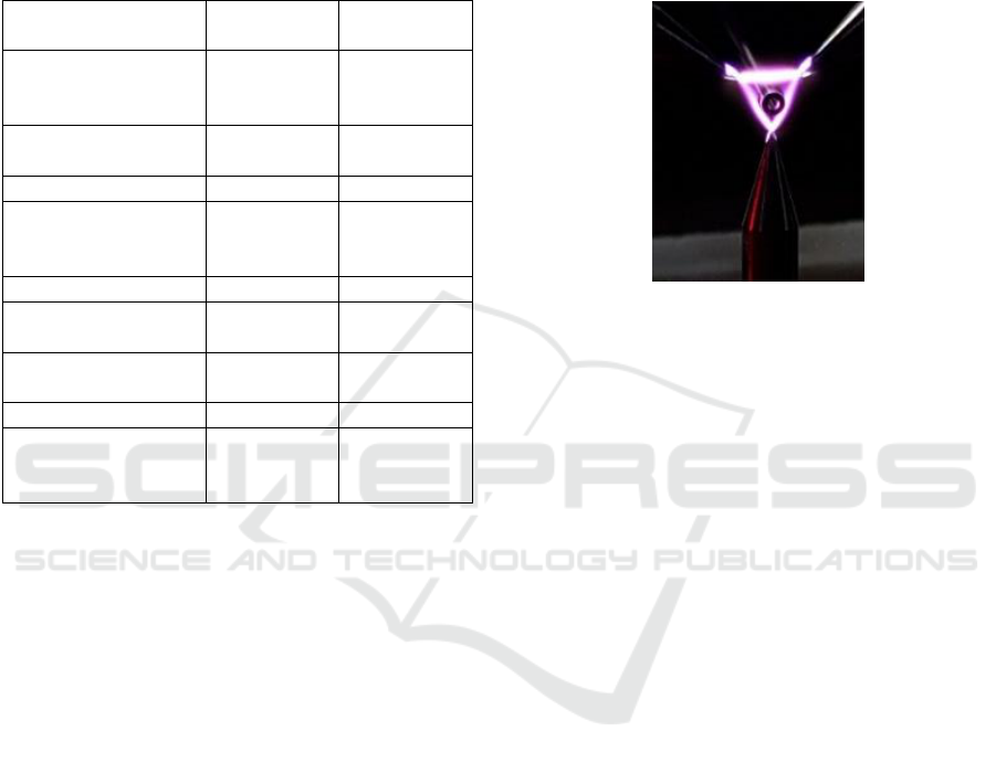
voltage high frequency (~ 30 kHz) source. An
example of a tube within the three-electrode plasma
discharge is shown in Figure 1.
Figure 1: Three-electrode plasma discharge for preform
fabrication.
2.2 Process Description
100 mm long synthetic quartz capillaries or tubes
with inner and outer diameters of 0.5 and 1 mm
respectively were used throughout this work. These
tubes were cleaned in an ultrasonic acetone bath and
heat-dried before the start of vapor deposition.
In most MCVD processes, the bubbler technique
is used for vapor deposition. A carrier gas, (typically
oxygen) is fed through liquid precursors such as
SiCl
4
, GeCl
4
, BBr
3
and POCl
3
to generate the
respective vapors to be further delivered into the
deposition chamber (Oh and Paek, 2012). In our case,
we adopted the evaporator method, where no carrier
gas is intentionally introduced but instead the
pressure inside the precursor container is maintained
at positive level, which is controlled by the
temperature of the container. Due to the formation of
a negative pressure gradient extending towards the
tube, the precursor vapor used for this study, i.e. SiCl
4
vapor, is channeled through the cleaned and surface
heated tubes. Hence, it is crucial to heat the tube
evenly so as to achieve uniform axial deposition. One
thing to note is that the SiCl
4
is highly volatile and
expands in volume when changing states. It is also
highly sensitive to moisture, and producing corrosive
HCl fumes. Hence a cool and dry environment is a
must for safety.
To fabricate the active fiber, rare-earth (RE)
dopants need to be deposited on the inner side of the
hollow tube. Conventionally, this is done either by
PHOTOPTICS 2018 - 6th International Conference on Photonics, Optics and Laser Technology
186

solution doping (Townsend et al., 1987) or
nanoparticle deposition (Tammela et al., 2002). We
employed the former method for our mini preform
fabrication for its simplicity.
The RE dopant solutions are prepared by mixing
and dissolving various weight ratios of RE chloride
hydrates in methanol. In this investigation, the
following RE solutions were used: 10 g of
YbCl3.6H2O and 20 g of AlCl3.6H2O dissolved in
200 ml of methanol for Ytterbium doped fiber, and 1
g of ErCl3.6H2O and 20 g of AlCl3.6H2O dissolved
in 200ml of methanol for Erbium doped fiber. High
RE doping concentrations were selected to
demonstrate the feasibility of the proposed technique.
The vapor-deposited tubes were then immersed in
the RE dopant solutions for 30 to 60 minutes, blow-
dried by oxygen gas and heated at about 200 C for 5
minutes to evaporate residual solvent and moisture.
We then replicate the recipe-driven fire polishing,
sintering, collapsing and sealing processes in the
three-electrode plasma system. The process is semi-
automated using National Instruments LabVIEW
software to improve its repeatability and efficiency.
Instead of moving the flame as in the standard
fabrication process, we move the tube back and forth
within the stationary ‘Ring of Fire’. Depending on
factors such as thickness of deposited soot and RE
layers, tube dimensions, and material properties of the
tube, the process requires optimization of variables
(e.g. plasma power, tube traversing speed) for good
performance as well as the elimination of trapped air
bubbles in the preform. For ~ 20 mm long preform
used in this study, the entire sintering, collapsing and
sealing processes took about 30 – 40 minutes. The
average collapsed tube diameter was ~ 870 µm. The
typical recipe used for fabrication, and its
corresponding outer diameter is depicted in Figure 2.
Figure 2: Typical recipe used in the process and its
corresponding outer diameter.
In standard fiber pulling process, the preform is
heated close to the melting point of silica in a furnace
or oven at the top of the fiber drawing tower, a thin
fiber can then be pulled from the lower end of the
preform. The intended fiber diameter can be
controlled by the pulling speed and the furnace
temperature. Before the fiber is wound up, it usually
receives a polymer coating such as acrylate, silicone
or polyimide for mechanical and chemical protection.
Since our fabricated preforms are significantly
smaller, the above mentioned method is not feasible.
Here, the horizontal tapering method was adopted
instead. Similarly, the pulling speed and the power of
the flame require optimization for desired fiber
diameters.
In principle, the fabricated preforms can be drawn
into fibers of any diameter narrower than that of the
preforms. The maximum fiber length that can be
drawn from a given preform dimension is calculated
based on the following relationship, where l
p
is the
length of preform, r
p
and r
f
are the radii of the preform
and fiber respectively.
2
f
p
pf
r
r
ll
(1)
3 RESULTS AND DISCUSSION
3.1 Physical Dimensions
Using the proposed method, we have successfully
fabricated several ~ 20 mm long ~ 870 µm diameter
preforms doped with either Ytterbium or Erbium.
These preforms were pulled to fibers with a final
diameter of 400 µm and lengths ranging from 50 to
75 mm. The typical fiber end face of the fiber is
depicted in Figure 3. The core is clearly seen, albeit
not perfectly circular in shape. This is mainly due to
the unevenness in the solution doping or slight mis-
alignment of the tube in the ‘Ring of Fire’. As we
pointed out at the beginning of this article, the focus
of our proposed technique is rapid prototyping at
early research phases, prior to scale-up and / or
further development for applications. The typical
cladding size of the fibers is shown in Figure 4. The
maximum cladding size variation is estimated to be ±
10 µm, or about ± 2.5 % for the 400 µm fiber. The
refractive index profiles of the fabricated fibers vary
from one to another, depending on the solution
composition and recipe used in the development.
Nonetheless, a typical index profile is depicted in
Figure 5 for illustration purpose.
Benchtop Mini Preform Fabrication for Specialty Optical Fibers
187
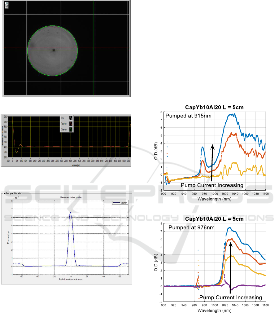
Figure 3: Typical fiber end face.
Figure 4: Cladding diameter showing uniformity
throughout the axial length.
Figure 5: Typical refractive index profile of the fabricated
fiber.
3.2 Spectral Performance
To analyze the spectra behavior of the fabricated
fiber, the fiber was spliced to a piece of passive fiber
for ease of connection and analysis. It was illuminated
by a tungsten halogen light source covering the
spectral range from 360 nm to 2000 nm, and pumped
either by 915 nm or 976 nm laser sources, depending
on the fibers’ RE dopants. The spectra were captured
using the optical spectrum analyzer (OSA) AQ-6315.
Reference spectrum was also taken using the similar
manner, however with only passive fiber.
The spectra behavior of the fabricated ~ 50 mm
Ytterbium doped silica fiber when pumped at 915 nm
and 976 nm are illustrated in Figure 6 (a) and (b). The
emission spectra of the fiber (with respect to the
reference) can be clearly seen even for such a short
length of fiber. We believe that this is mainly due to
the high doping concentration of the RE element,
which in turn demonstrated the capability of our
fabrication technique and its potential with other RE
dopant choices. More importantly, this marks the
initial success of the method.
a
b
Figure 6: Transmission spectra of the fabricated Ytterbium
doped silica fiber when pumped at (a) 915 nm; (b) 976 nm.
We further investigate the method using Erbium
as another active element. The spectra of the fiber
when pumped at 976 nm were obtained as follows.
Once again the amplified spontaneous emission
(ASE) spectra of the Erbium doped silica fiber can be
observed, indicating the successful incorporation of
Erbium dopants within the fiber.
PHOTOPTICS 2018 - 6th International Conference on Photonics, Optics and Laser Technology
188

Although the fibers fabricated show promising
spectral results, they suffer from high background
loss, this is mainly due to the purity and preparation
environment and method of the samples.
Furthermore, clean room environment was not
utilized during the process.
Nonetheless, we would like to perceive this
shortcoming in a positive manner: i.e. clean room
environment is not necessary for this prototyping
process, although it would be good for potential better
results. To further improve the fabrication precision,
tighter control of the temperature is essential. This
“quick and dirty” process can be adopted until one is
satisfy with the doping solution composition before
switching it to the standard fabrication for good
quality fibers.
Figure 7: Spectra behavior of the fabricated Erbium doped
silica fiber when pumped at 976 nm.
4 CONCLUSIONS
In conclusion, we have demonstrated a concept of
miniaturizing the standard fiber fabrication processes
to a benchtop version with repeatable results. We
have also successfully fabricated rare earth doped, i.e.
Ytterbium and Erbium doped silica fibers using the
method incorporating with solution doping technique,
and obtained reasonable spectra results. Undeniably,
the length and quality of the fibers are traded-off by
the time and cost involved. This process is beneficial
for those who are requiring small quantity of the
specialty optical fiber for rapid prototyping purposes,
especially for the less mature optical fiber
technologies, such as soft-glasses fibers. It also opens
up the possibilities of exploring other glass hosts with
various materials and compositions in a smaller scale.
ACKNOWLEDGEMENTS
This work is funded by Temasek Laboratories @
NTU (Grant No: 9016100134). We acknowledge the
technical support by the laboratory managers and
technical support officers of OPTIMUS and COFT,
NTU
REFERENCES
T. Izawa, 2000, “Early days of VAD process,” IEEE J. Sel.
Topics Quantum Electron. 6, 1220 – 1227.
V. Petit, A. L. Rouge, F. Beclin, H. E. Hamzaoui, and L.
Bigot, 2010, “Experimental study of SiO2 soot
deposition using the outside vapor deposition method,”
Aerosol Science and Tech. 44, 388 – 394.
M. Blankenship, and C. Deneka, 1982, “The outside vapor
deposition method of fabricating optical waveguide
fibers,” IEEE J. Quantum Electron. 18, 1418 – 1423.
J. Cho, J. Kim, and M. Choi, 1998, “An experimental study
of the heat transfer and particle deposition during the
outside vapor deposition process,” Int J. Heat and Mass
Transfer 41, 435 – 445.
S. R. Nagel, J. B. MacChesney, and K. L. Walker, 1982,
“An overview of the modified chemical vapor
deposition (MCVD) process and performance,” IEEE J.
Quantum Electron. 18, 459 – 476.
V. Matejec, M. Hayer, M. Pospisilova, and I. Kasik, 1997,
“Preparation of optical cores of silica optical fiber by
the sol-gel method,” J. Sol-Gel Science Tech. 8, 889 –
893.
J. L. Auguste, G. Humbert, S. Leparmentier, M. Kudinova,
P. O. Martin, G. Delaizir, K. Schuster, and D.
Litzkendorf, 2014, “Modified powder-in-tube
technique based on the consolidation processing of
powder materials for fabricating specialty optical
fibers,” Materials 7, 6045 – 6063.
S. Tammela, P. Kiiveri, S. Sarkilahti, M. Hotoleanu, H.
Vaikonen, M. Rajala, J. Kurki, and K. Janka, Sep 2002,
“Direct nanoparticle deposition process for
manufacturing very short high gain Er-doped silica
glass fibers” presented at 28th European Conference on
Optical Communication (ECOC), Copenhagen.
J. E. Townsend, S. B. Poole, and D. N. Payne, 1987,
“Solution-doping technique for fabrication of rare-
earth-doped optical fibers,” Elec. Lett. 23, 329 - 331.
K. Oh and U. Paek, 2012, “Preform fabrication and optical
fiber drawing process” in Silica Optical Fiber
Technology for Devices an Components – Design,
Fabrication, and International Standards, Wiley, pp. 83
- 130.
Benchtop Mini Preform Fabrication for Specialty Optical Fibers
189
