
Orientation Beautification of Reverse Engineered Models
S. Gauthier
1,2
, W. Puech
1
, R. B
´
eni
`
ere
2
and G. Subsol
1
1
LIRMM Laboratory, CNRS, Univ. Montpellier, Montpellier, France
2
C4W, Montpellier, France
Keywords:
Reverse Engineering, Beautification, Geometric Constraints.
Abstract:
Today, it has become more frequent and relatively easy to digitize the surface of 3D objects and then to
reconstruct a boundary representation (B-Rep). However, the obtained results suffer from various inaccura-
cies, mainly caused by noisy data. In this paper, we present an efficient method to detect and rectify many
regularities approximately present in an object. We propose to extract global parallelism and orthogonality
constraints, then locally and independently adjust the geometric primitives (planes, cylinders, spheres, cones).
We first retrieve orientations from primitives (normals, axes), then compute an orthonormal coordinate system.
Finally, we adjust each primitive orientation according to spherical coordinates. Our objective is to design a
fast and automatic method, which is seldom seen in reverse engineering. Experimental results applied on
reverse engineered 3D meshes show the efficiency and the robustness of our proposed method.
1 INTRODUCTION
An industrial reverse engineering application aims to
reconstruct an object as a combination of geometric
primitives, from a digitized 3D mesh or a 3D point
cloud (Benk
˝
o et al., 2001)(B
´
eni
`
ere et al., 2013). For
mechanical objects, we search for geometric primi-
tives such as planes, spheres, cylinders and cones, but
also tori and more generally developable or ruled sur-
faces. To reconstruct the original geometry, we must
take into account the shape of each primitive and their
relationships with each other. But an objects shapes
can be very complex, and the measured data can of-
ten be noisy. It then requires a post-processing step
to adjust and regularize the primitive parameters ac-
cording to some practical, applicative or design rules
based in general on parallelism, orthogonality, quan-
tization of parameters and regularity. This is known
as the beautification step (Langbein et al., 2001).
Moreover, the objective of a reverse engineering
process is also to retrieve the design intent of an ob-
ject. In this paper, we propose a method to adjust the
different orientations present in a reverse engineered
model. We first use the geometric primitive orien-
tations to detect parallelism and orthogonality con-
straints. Then, we extract an implicit orthonormal co-
ordinate system from the object, which is then used to
adjust the orientations according to some geometric
dimensioning and tolerancing constraints (GD&T).
This allows us to adjust each primitive independently
according to global orientation constraints, avoiding
many problems such as error propagation for exam-
ple.
This paper is organized as follows. Previous work
in this topic is presented in Section 2. In Section 3,
we present in detail our orientation beautification pro-
cess. In Section 4, we apply our proposed beautifica-
tion on reverse engineered 3D models and we show
that our method improves the obtained results. Fi-
nally, in Section 5, we conclude and propose direc-
tions for future research.
2 PREVIOUS WORK
In reverse engineering, several methods propose to
extract geometric primitives with minimal user help
(Buonamici et al., 2017). They result in providing a
reverse engineered model, i.e. a set of geometric pa-
rameterized primitives (segments of planes, spheres,
cylinders, cones, tori) but they do not formally take
into account geometric constraints like parallelism,
orthogonality or concentricity, which are induced by
the design process (Wang et al., 2012). For this pur-
pose, it is possible to apply a separate step called
beautification (Langbein et al., 2002).
The beautification method proposed in (Langbein
et al., 2004) consists in detecting many regularities
that are approximately present in the reverse engi-
neered model, like constant angles (resp. distances)
Gauthier, S., Puech, W., Bénière, R. and Subsol, G.
Orientation Beautification of Reverse Engineered Models.
DOI: 10.5220/0006606000910100
In Proceedings of the 13th International Joint Conference on Computer Vision, Imaging and Computer Graphics Theory and Applications (VISIGRAPP 2018) - Volume 1: GRAPP, pages
91-100
ISBN: 978-989-758-287-5
Copyright © 2018 by SCITEPRESS – Science and Technology Publications, Lda. All rights reserved
91
between pairs of directions (resp. positions) for ex-
ample. Then, a selection of a constraint subset is
applied to reduce the complexity and ensure that the
constraint system have at least one solution. Finally,
other constraints are iteratively added to the system
until a fully constrained model is obtained. The dif-
ficulty in this method is to guarantee the consistency
of the constraint subset. Indeed, at each step, many
verifications are required to ensure that there are no
contradictions between the constraints.
In (Li et al., 2011), the beautification process is as-
sociated with a RANSAC approach to iteratively add
new geometric primitives and adjust them to respect
global alignments. At each step, the primitive extrac-
tion algorithm is more accurate, but a large number
of primitives needs to be adjusted. Since this method
investigates primitives by pairs, this can lead to an un-
desired error accumulation across primitives.
The beautification process proposed by (Kov
´
acs
et al., 2015) consists in detecting local and global
symmetry and continuity constraints between the
primitives. In this method, a constrained fitting is pro-
posed to respect continuity constraints, like tangency,
between the primitives. Moreover, a Gaussian sphere
of plane orientations is used to determine dominant
clusters. A grid is then constructed to detect symme-
tries and adjust the primitives. The Gaussian sphere
used in this method is very interesting, since it allows
to extract global orientations. A keypoint to highlight
is the constrained fitting method, which is compre-
hensively analyzed in (Benk
˝
o et al., 2001).
To simplify the beautification step, we propose
to detect global constraints, which are easier to sat-
isfy. In this paper, we present a new method which
deals with object orientations, and particular angle
constraints, including parallelism and orthogonality.
3 BEAUTIFICATION PROCESS
In the following, we assume that we have extracted
geometric primitives (planes, spheres, cylinders and
cones) and their parameters from a digitized 3D mesh.
We used the method described in (Gauthier et al.,
2017) but many other methods are available (Buon-
amici et al., 2017).
3.1 Overview of the Process
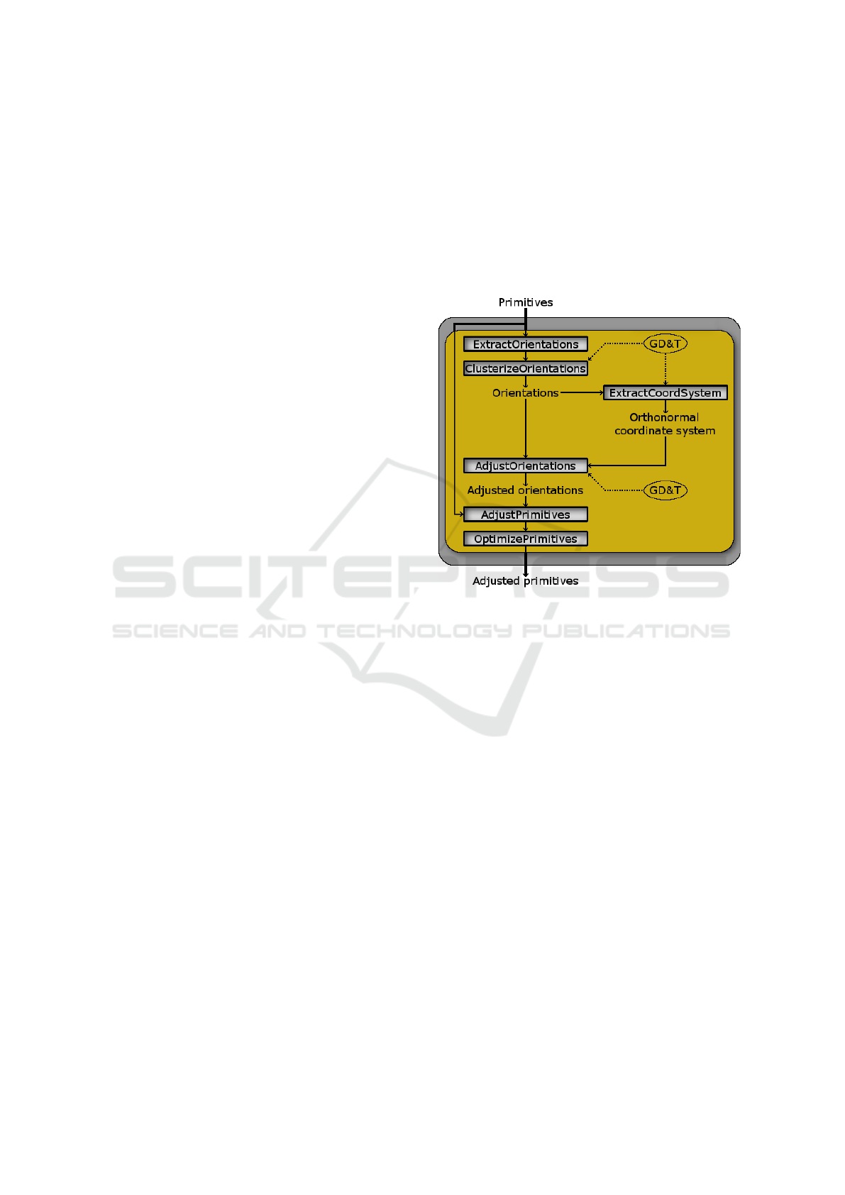
As illustrated in Fig.1, our proposed method is com-
posed of six steps. First, we extract orientations di-
rectly from the parameters of geometric primitives,
but also from other geometric features such as the
intersections between planes and we clusterize them
into orientation groups (Section 3.3). These orienta-
tion groups allow us to compute an intrinsic orthonor-
mal coordinate system from the object (Section 3.4).
Then, we use this coordinate system to adjust the
orientation clusters (Section 3.5), according to some
geometric dimensioning and tolerancing parameters
(Section 3.2). Finally, we can adjust each primitive
according to these adjusted orientations, and optimize
them without orientation modification (Section 3.6).
Figure 1: Overview of the beautification process.
3.2 Geometric Dimensioning and
Tolerancing (GD&T)
Geometric Dimensioning and Tolerancing (GD&T)
is a system defining engineering tolerances. It is
used by designers when they model (3D) mechan-
ical objects. There are several standards available
worldwide, like ASME (https://www.asme.org/)
and ISO (https://www.iso.org/), but these are
too complex to use in a reverse engineering process.
Thus, we define very simplified rules using simple ge-
ometric tolerances.
We are going to use two tolerance parameters in
order to control our orientation beautification process:
• Tolerance: Angle tolerance to define two similar
orientations.
• Quantization: Array of possible angles between
an orientation and a plane of an orthonormal co-
ordinate system, which is implicitly defined by the
model itself (see Section 3.4).
GRAPP 2018 - International Conference on Computer Graphics Theory and Applications
92
3.3 Orientation Extraction and
Clustering
3.3.1 Orientation Extraction
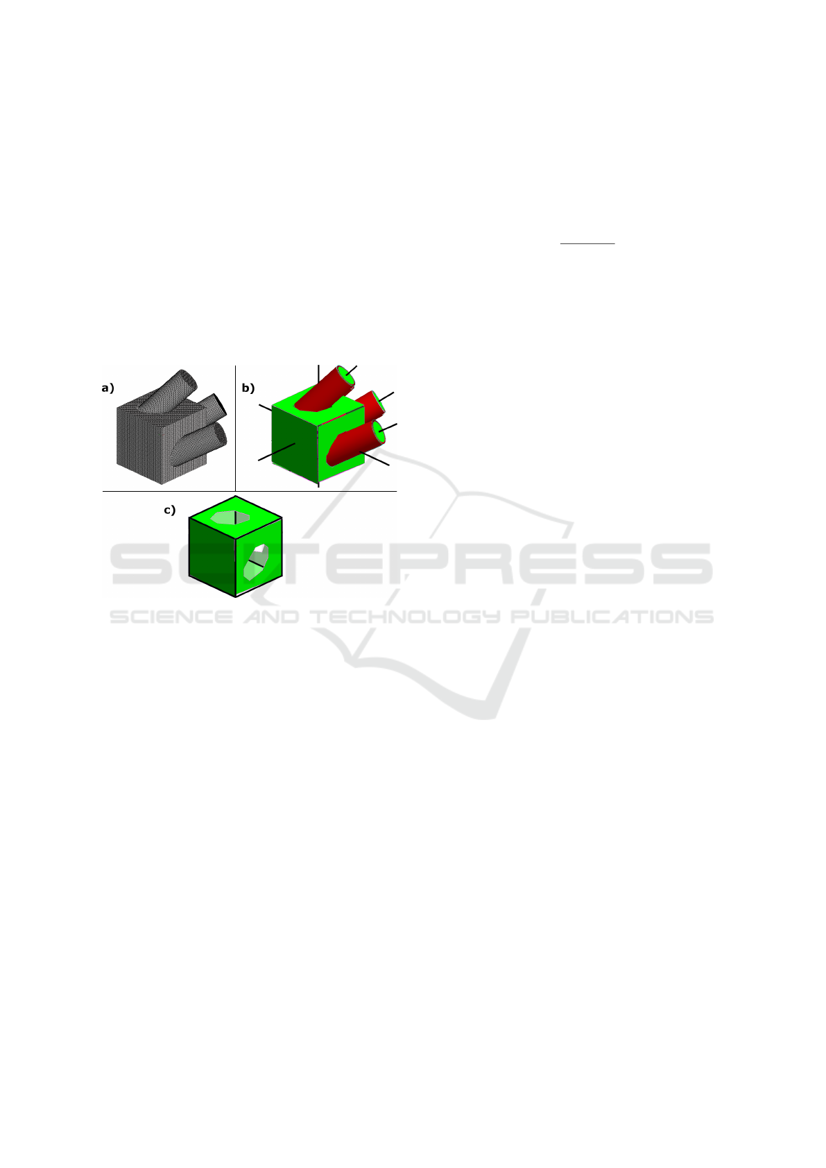
In a 3D object, we can intuitively find several orienta-
tions (see Fig.2). These are mostly defined by the pa-
rameters of the geometric primitives (e.g. the axis of
a cylinder or the normal to a plane), but they may also
be given by other geometric features, such as intersec-
tion lines between planes or alignments between the
centers or the apices of identical primitives for exam-
ple.
Figure 2: Orientation extraction from other informations: a)
Original 3D mesh, b) Extracted primitives, c) Intersection
lines between planes.
These geometric features are very important as the
reverse engineering process can fail to extract some
primitives and their associated parameters.
3.3.2 Orientation Clustering
Extracted orientations often suffer from inaccuracies,
mostly caused by noise in the reverse engineered
model. We then have to clusterize similar orienta-
tions into groups. In our method, similar orientations
correspond to pairs of lines with an angle less than
Tolerance (see Section 3.2).
We first need to separate orientation vectors into
similar vector sets, with a clustering algorithm. The
clustering process is straightforward. We perform the
three steps until all the orientation vectors have been
processed:
• Take an orientation vector at random which is not
clustered. It will create a new cluster/group.
• Retrieve similar orientation vectors according to
the tolerance and add them to the group.
• Iterate this last step by comparing the orientation
vectors with all the ones belonging to the cluster
until there are no vectors left to add.
Then, for each group, we can compute an average
orientation by:
C =
∑
n
i=1
ω
i
V
i
∑
n
i=1
ω
i
, (1)
where C is the average orientation, V
i
a normalized
orientation vector from the similar vector set and ω
i
the weight associated to V
i
, corresponding to the area
of the geometric primitive.
And a group weight W
c
by:
W
c
=
n
∑
i=1
ω
i
. (2)
Implicitly, this clustering groups parallel orienta-
tions, according to the tolerance. This allows us to
extract global constraints of parallelism, since all the
parallel primitives are grouped at the same time. This
is an important point in our process, which simplifies
the global adjustment of the orientations and avoids
many problems like error propagation. Indeed, many
processes can begin by a particular primitive and ad-
just the neighbors by propagation (Chen and Feng,
2015). But the first primitive, often the most accu-
rate one, is not necessarily the best one to minimize
a global error. With our process, each primitive is
adjusted independently and according to global infor-
mations.
3.4 Model Reference Frame Extraction
We use the orientation clusters to construct the orien-
tation graph, as illustrated in Fig.3:
• A primitive node represents a primitive which is
defined by an orientation (green squares for planes
and red circles for cylinders). Its value is given by
the primitive area.
• A cluster node (grey and purple stars) represents
an orientation cluster. Its value is given by the
weight W
c
.
• An edge between a primitive node and a cluster
node represents the inclusion of the primitive ori-
entation in the cluster. These edges represent the
parallelism constraints.
• An edge between two cluster nodes is added when
the orientation of two clusters are orthogonal, ac-
cording to the tolerance parameter.
This graph allows us to display parallelism and
orthogonality relationships between all the oriented
primitives of the reverse engineered model. We can
Orientation Beautification of Reverse Engineered Models
93
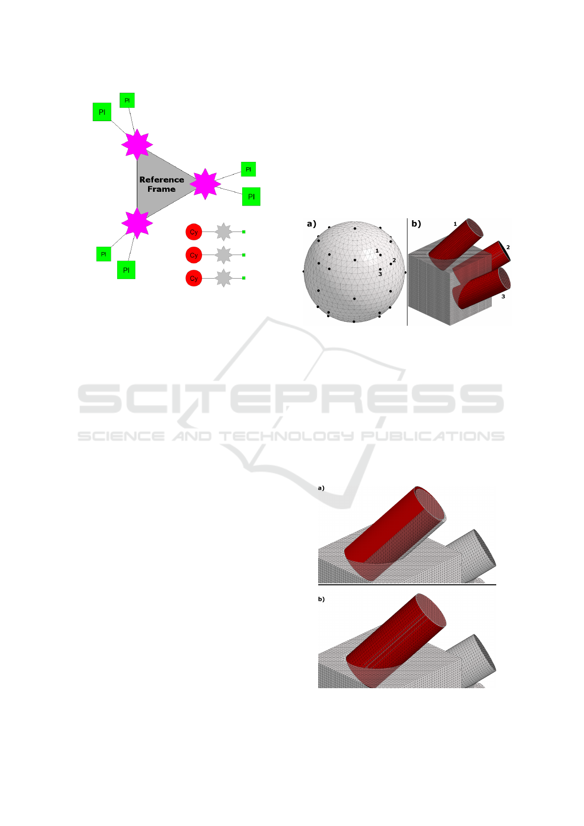
Figure 3: Orientation graph from Fig.2.b.
now detect all the cycles of 3 cluster nodes. The cycle
with the highest sum of cluster weights is the one that
maximizes the covered area of the object (see Fig.3).
If we take this cycle, we find a set of three orthogo-
nal orientations which are related at best to the prim-
itives. This defines a reference frame intrinsic to the
model which could be considered as the frame used
by the CAD operator to design the object. This frame
will then be used to define all the allowed orientations
with respect to the quantization parameter. If there is
no cycle, we take the maximal segment of 2 clusters
and we compute the cross-product between the two
cluster orientations to complete the reference frame.
If, unfortunately, there is neither a cycle nor a seg-
ment, we take the maximal orientation cluster as the
reference frame only axis.
3.5 Orientation Quantization
In this section, we aim to adjust all the primitive ori-
entations, according to the global frame and the quan-
tization parameter (see Section 3.2). If we assume that
the reference frame was the one used by the designer,
we can use spherical coordinates to quantify orienta-
tions and we get the following:
x = ρsinφcos θ
y = ρsinφsin θ
z = ρcosφ
, (3)
where the vector (x, y, z) is an allowed orientation vec-
tor, ρ its norm and (φ, θ) a couple of angles from
Quantization (see Section 3.2). Each possible couple
(φ, θ) defines a different reference orientation.
Note that the order of the frame axes is important
for spherical coordinates. Since we do not know ex-
actly the original order, we must take into account the
3 possible systems of spherical coordinates by permu-
tating O
x
, O
y
and O
z
. Each cluster orientation is then
adjusted according to the closest allowed orientation
(i.e. the one defining the smallest angle with the clus-
terized orientation whatever the order of axes). This
implies that all the primitives belonging to this cluster
should be adjusted with respect to the cluster orien-
tation. Fig.4 illustrates the 3 possible systems on a
specifically designed object.
Figure 4: a) Gaussian sphere of allowed orientations and b)
Cylinders along the 3 possible systems for 45
◦
rotations.
3.6 Primitive Adjustment
The last step of our method consists in adjusting each
geometric primitive by using its quantified orienta-
tion. It is not sufficient to modify the orientation pa-
rameter of the primitive by applying a 3D rotation
leaving the other parameters unchanged. We have to
apply a constrained optimization on each primitive,
with respect to the fitted mesh, as illustrated in Fig.5.
Figure 5: Constrained optimization with locked orientation:
a) Reoriented cylinder, b) Constrained optimization.
GRAPP 2018 - International Conference on Computer Graphics Theory and Applications
94
In this step, the orientation is fixed but all the other
parameters (a 3D point for a plane, a 3D point and
a radius for a cylinder, the apex and the angle for a
cone) are optimized. We used the formulas proposed
in (Shakarji, 1998).
4 EXPERIMENTAL RESULTS
In this section, we applied our method on the
digitized mesh of a case study to show each
step in detail. After, we performed some ex-
periments on more complex digitized 3D meshes.
All of these results were obtained with the same
parameters: Tolerance = 1
◦
and Quantization =
{0
◦
, 30
◦
, 45
◦
, 60
◦
, 90
◦
, 120
◦
, 135
◦
, 150
◦
}.
4.1 Case Study: Lattice
Using a CAD application, we designed a lattice-
shaped object which is mainly composed of cylinders,
as illustrated in Fig.6. We designed it with particular
orientations, according to the reference frame XY Z.
Figure 6: 3D CAD mesh of Lattice.
Then, we printed it using a professional 3D printer
(Ultimaker3), which is accurate to within 20 microns.
Finally, we have digitized it with a structured light
scanner (IMetric), which is accurate to within 10 mi-
crons (see Fig.7). No post-processing was performed.
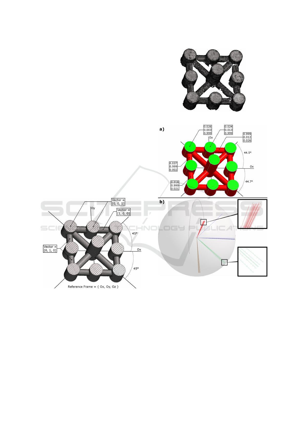
We extracted the geometric primitives (i.e. the
type of primitives and their parameters) with the
method described in (Gauthier et al., 2017) and we
obtained all of the 21 cylinders . Nevertheless, when
we display the parameters of the axes, we can observe
that they have slightly deviated with respect to the the-
oretical directions, as illustrated in Fig.8.
Figure 7: 3D digitized mesh of Lattice.
Figure 8: Lattice: a) Extracted primitives and b) Gaussian
sphere of orientations, without orientation beautification.
We applied our orientation beautification pro-
cess and we can see in Fig.9 the constructed graph
(Fig.9.a) and the computed reference frame (Fig.9.b).
The orientation graph contains two cycles of 3 cluster
nodes, corresponding to possible coordinate systems.
Our algorithm finds a reference frame corresponding
to XY Z, which is the coordinate system used while
designing the object.
In Fig.10, we show final results after beautifica-
tion. Note that the adjusted orientations exactly cor-
respond to the designed ones (Fig.6), and so respect
the particular angles of 45 degrees.
Orientation Beautification of Reverse Engineered Models
95
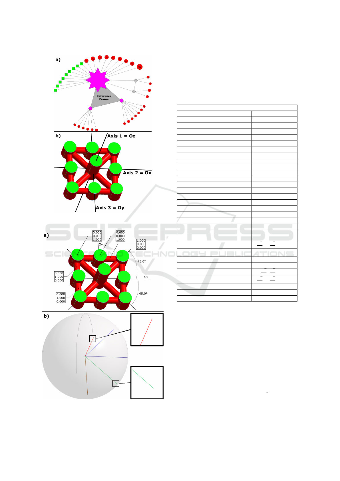
Figure 9: Lattice: a) Constructed orientation graph and b)
Computed reference frame.
Figure 10: Lattice: a) Adjusted primitives and b) Gaussian
sphere of orientations, with orientation beautification.
Table 1 summarizes the different extracted orien-
tations. The first column corresponds to the orienta-
tions from the extracted primitives in Fig.8.a, and the
second column shows the orientations of the adjusted
primitives in Fig.10.a.
Table 1: Results of our beautification on Lattice. See Fig.8.a
for the first column and Fig.10.a for the second column.
Orientation
Before After
V
1
= [0.026, 0.003, 0.999] [0, 0, 1] = C
1
V
2
= [0.024, 0.013, 0.999] [0, 0, 1] = C
1
V
3
= [0.015, 0.012, 0.999] [0, 0, 1] = C
1
V
4
= [0.023, −0.007, 0.999] [0, 0, 1] = C
1
V
5
= [−0.020, −0.004, −0.999] [0, 0, −1] = C
1
V
6
= [0.014, 0.010, 0.999] [0, 0, 1] = C
1
V
7
= [0.016, −0.005, 0.999] [0, 0, 1] = C
1
V
8
= [0.012, −0.014, 0.999] [0, 0, 1] = C
1
V
9
= [0.022, −0.012, 0.999] [0, 0, 1] = C
1
V
10
= [−0.018, −0.011, −0.999] [0, 0, −1] = C
1
V
11
= [−0.022, −0.016, −0.999] [0, 0, −1] = C
1
V
12
= [−0.018, 0.005, −0.999] [0, 0, −1] = C
1
V
13
= [−0.021, 0.002, −0.999] [0, 0, −1] = C
1
V
14
= [−0.024, 0.000, −0.999] [0, 0, −1] = C
1
V
15
= [−0.028, 0.001, −0.999] [0, 0, −1] = C
1
V
16
= [−0.018, 0.020, −0.999] [0, 0, −1] = C
1
V
17
= [−0.022, 0.026, −0.999] [0, 0, −1] = C
1
V
18
= [−0.029, 0.021, −0.999] [0, 0, −1] = C
1
V
19
= [−0.999, 0.026, 0.034] [−1, 0, 0] = C
2
V
20
= [−0.999, 0.012, 0.026] [−1, 0, 0] = C
2
V
21
= [−0.037, −0.999, 0.002] [0, −1, 0] = C
3
V
22
= [0.686, −0.728, −0.015] [
√
2
2
, −
√
2
2
, 0] = C
4
V
23
= [0.732, 0.682, 0.017] [
√
2
2
,
√
2
2
, 0] = C
5
V
24
= [−0.013, −0.999, 0.015] [0, −1, 0] = C
3
V
25
= [−0.018, −0.999, −0.021] [0, −1, 0] = C
3
V
26
= [0.732, 0.682, 0.006] [
√
2
2
,
√
2
2
, 0] = C
5
V
27
= [0.687, −0.726, −0.004] [
√
2
2
, −
√
2
2
, 0] = C
4
V
28
= [−0.036, −0.999, 0.003] [0, −1, 0] = C
3
V
29
= [−0.999, 0.027, 0.014] [−1, 0, 0] = C
2
V
30
= [−0.999, 0.031, 0.035] [−1, 0, 0] = C
2
Before beautification, the Lattice digitized mesh
contains 30 different orientations. After the clustering
step, we obtain only 5 different orientations. Finally,
after the orientation adjustement, we obtain orienta-
tions which exactly correspond to the designed ones.
Indeed, the resulting orientations are either colinear
to coordinate system axis, or rotated by 45 degrees
around Oz.
4.2 Other Digitized Meshes
Fig.11 shows some angles between the different ori-
entations of the digitized object Lego
small (struc-
tured light scanner accurate to within 10 microns), be-
fore (Fig.11.b) and after (Fig.11.c) the beautification
step. We can see that no two orientations are exactly
GRAPP 2018 - International Conference on Computer Graphics Theory and Applications
96
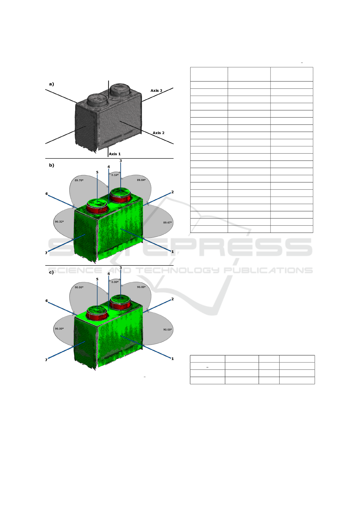
parallel or orthogonal at first, but our beautification
process can satisfy these constraints.
Figure 11: Local orientation angles on Lego small: a) 3D
mesh and computed orthonormal coordinate system, b) An-
gles before beautification, c) Angles after.
Angles formed by pairs of orientations are sum-
marized in Table 2, before and after the global orien-
tation beautification.
We can see that our process correctly adjusts ori-
entations to satisfy parallelism and orthogonality. We
can also observe that our method does not round an-
Table 2: Local results of our beautification on Lego small.
Orientation Angle before Angle after
couple beautification beautification
1 - 2 89.67
◦
90.00
◦
1 - 3 90.36
◦
90.00
◦
1 - 4 90.19
◦
90.00
◦
1 - 5 89.93
◦
90.00
◦
1 - 6 0.41
◦
0.00
◦
1 - 7 90.28
◦
90.00
◦
2 - 3 89.84
◦
90.00
◦
2 - 4 89.88
◦
90.00
◦
2 - 5 90.02
◦
90.00
◦
2 - 6 89.71
◦
90.00
◦
2 - 7 0.68
◦
0.00
◦
3 - 4 0.16
◦
0.00
◦
3 - 5 0.46
◦
0.00
◦
3 - 6 89.94
◦
90.00
◦
3 - 7 89.54
◦
90.00
◦
4 - 5 0.30
◦
0.00
◦
4 - 6 89.78
◦
90.00
◦
4 - 7 89.58
◦
90.00
◦
5 - 6 89.51
◦
90.00
◦
5 - 7 89.72
◦
90.00
◦
6 - 7 90.32
◦
90.00
◦
gles, as illustrated in Table 2 in bold. Indeed, we can
believe that these angles were rounded because the
initial object is accurate enough to almost respect the
parallelism and orthogonality constraints.
Table 3 shows the computational time and the
mean of corrected orientation angles, in degrees, for
each presented object. As we can see, our presented
method is fast: only one second to process hundreds
of primitives. This is thanks to our global constraint
detection and local independent primitive adjustment.
Therefore, our beautification process is suitable for an
industrial application like reverse engineering. More-
over, these results were obtained according to the in-
put tolerances, which allows a certain flexibility and
adaptability in primitive adjustments.
Table 3: Mean angle correction of orientations.
Mesh Primitives Time Correction
Lego small 9 <1s 0.39
◦
Aerospace 115 1s 0.64
◦
Watertight 306 1s 0.71
◦
Fig.12 shows a complex object, Watertight (un-
known scanner). As illustrated in Fig.12.a, we suc-
cessfully extracted a reference frame corresponding
to the main and side holes. Since the digitized 3D
mesh is noisy, we extracted many inaccurate orien-
tations before beautification and therefore different
angles between primitive orientations (see Fig.12.b).
Orientation Beautification of Reverse Engineered Models
97
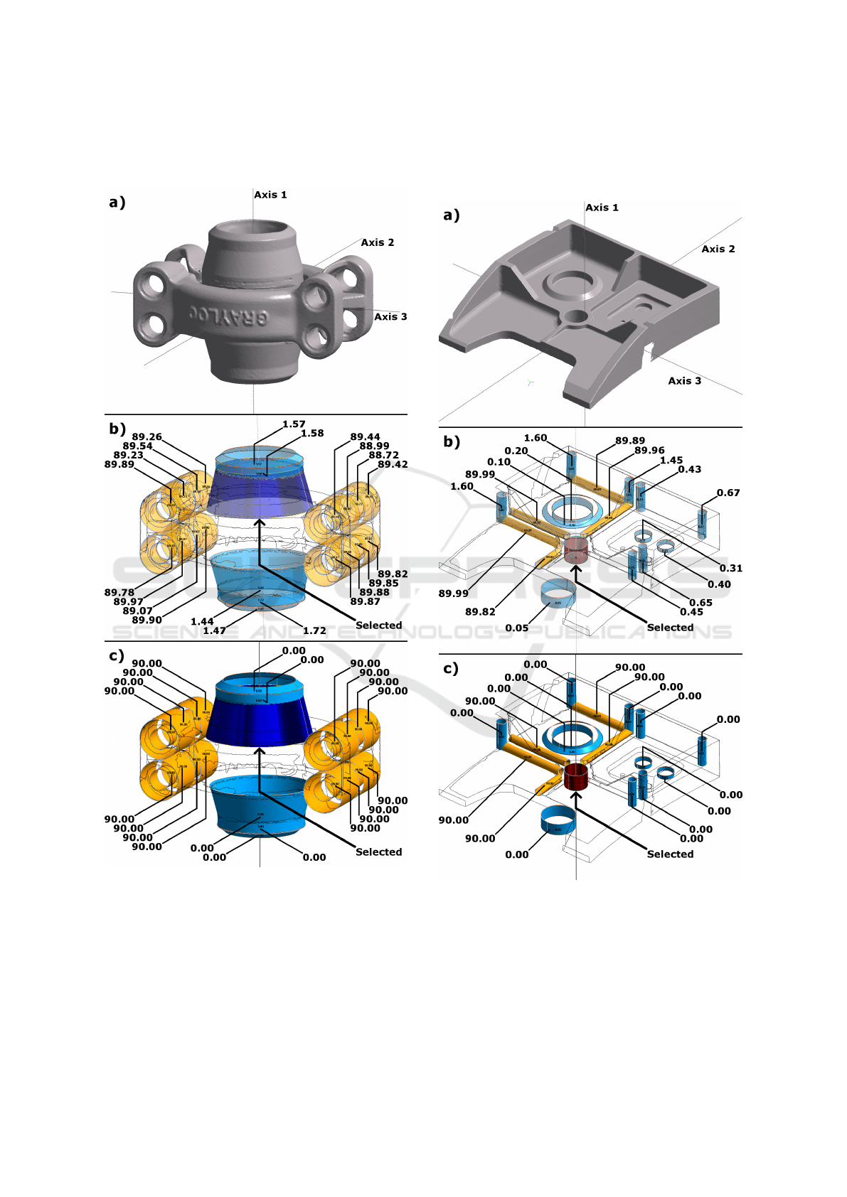
After beautification, we obtain more regular orienta-
tions and angles, according to GD&T (see Fig.12.c).
Figure 12: Beautification on Watertight: a) 3D mesh and
computed reference frame, b) c) Angles between selected
and other orientations b) Before beautification and c) After.
Fig.13 shows another object, Aerospace (struc-
tured light scanner accurate to within 10 microns). As
illustrated in Fig.13.a, the computed orthonormal co-
ordinate system most likely corresponds to the one
used by the designer. This object contains several dif-
ferent orientations which are neither parallel nor or-
thogonal (see Fig.13.b). After beautification, many
orientations become exactly parallel or orthogonal, as
illustrated in Fig.13.c.
Figure 13: Beautification on Aerospace: a) 3D mesh and
computed reference frame, b) c) Angles between selected
and other orientations b) Before beautification and c) After.
As illustrated in Fig.14, we notice that our beau-
tification does not only improve parallelism and or-
thogonality, but also other particular angles.
GRAPP 2018 - International Conference on Computer Graphics Theory and Applications
98
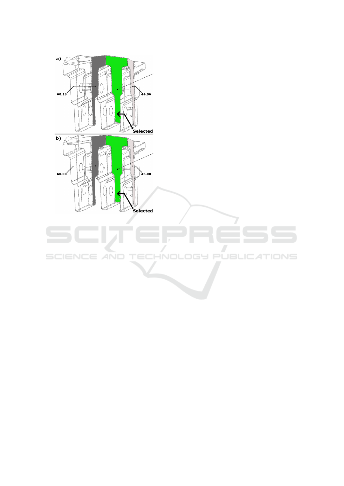
Figure 14: Aube: Angles between selected and other orien-
tations a) Before beautification and b) After.
5 CONCLUSION
In this paper, we presented a new beautification
method to optimize orientations of geometric primi-
tives detected in a digitized 3D object. We first detect
global parallelism and orthogonality constraints, then
compute an intrinsic orthonormal coordinate system,
we cluster all the orientations of the detected prim-
itives with respect to tolerance and quantization pa-
rameters, and finally adjust orientations using spher-
ical coordinates. We also apply a constrained opti-
mization of geometric primitives to guarantee the ad-
justment accuracy.
Computing an orthonormal coordinate system in-
trinsic to the object is essential, as it allows us to de-
fine global and consistent constraints of parallelism
and orthogonality for all the primitives at the same
time. Thanks to these constraints, we can indepen-
dently adjust the orientation of each geometric primi-
tive and avoid major problems like error propagation
for example. This process is a step towards a fully
automatic reverse engineering process, which aims to
retrieve the initial intent of the designer.
We have implemented the method in the 3D en-
vironment of the C4W society and tested it on sev-
eral different objects. The process is fast (a few
seconds) and it allows us to reduce the number of
orientations. We can see from our results that the
computed reference coordinate system on each ob-
ject most likely corresponds to the one used to design
it. Moreover, primitive orientations can be sucess-
fully adjusted with respect to numerous particular an-
gle values.
In future work, we propose to extend our method
to adjust not only orientations but other primitive pa-
rameters such as radius for spheres and cylinders, or
apex and angle for cones. Then we will extend it to
adjust the geometric primitive positions, respecting
several alignments and intersections.
REFERENCES
B
´
eni
`
ere, Subsol, Gesqui
`
ere, LeBreton, and Puech (2013).
A comprehensive process of reverse engineering from
3d meshes to cad models. Computer-Aided Design,
45(11):1382 – 1393.
Benk
˝
o, Martin, and V
´
arady (2001). Algorithms for re-
verse engineering boundary representation models.
Computer-Aided Design, 33(11):839 – 851.
Buonamici, Carfagni, and Volpe (2017). Recent strate-
gies for 3d reconstruction using reverse engineering:
a bird’s eye view. In Advances on Mechanics, Design
Engineering and Manufacturing (JCM 2016), pages
841–850. Springer International Publishing.
Chen and Feng (2015). Idealization of scanning-derived tri-
angle mesh models of prismatic engineering parts. In-
ternational Journal on Interactive Design and Manu-
facturing (IJIDeM), pages 1–17.
Gauthier, Puech, B
´
eni
`
ere, and Subsol (2017). Analysis of
digitized 3d mesh curvature histograms for reverse en-
gineering. Computers in Industry, 9293:67 – 83.
Kov
´
acs, V
´
arady, and Salvi (2015). Applying geometric con-
straints for perfecting cad models in reverse engineer-
ing. Graphical Models, 82:44 – 57.
Langbein, Marshall, and Martin (2002). Numerical meth-
ods for beautification of reverse engineered geometric
models. In Geometric Modeling and Processing. The-
ory and Applications. GMP 2002. Proceedings, pages
159–168.
Langbein, Marshall, and Martin (2004). Choosing con-
sistent constraints for beautification of reverse engi-
neered geometric models. Computer-Aided Design,
36(3):261–278.
Langbein, Mills, Marshall, and Martin (2001). Recognizing
geometric patterns for beautification of reconstructed
solid models. In Proceedings International Confer-
ence on Shape Modeling and Applications, pages 10–
19.
Li, Wu, Chrysathou, Sharf, Cohen-Or, and Mitra (2011).
Globfit: Consistently fitting primitives by discover-
ing global relations. ACM Trans. Graph., 30(4):52:1–
52:12.
Orientation Beautification of Reverse Engineered Models
99

Shakarji (1998). Least-squares fitting algorithms of the nist
algorithm testing system. In Journal of Research of
the National Institute of Standards and Technology,
pages 633–641.
Wang, Gu, Yu, Tan, and Zhou (2012). A framework for 3d
model reconstruction in reverse engineering. Comput.
Ind. Eng., 63(4):1189–1200.
GRAPP 2018 - International Conference on Computer Graphics Theory and Applications
100
