
Reducing UML Modeling Tool Complexity with Architectural
Contexts and Viewpoints
Maged Elaasar
1
, Florian Noyrit
2
, Omar Badreddin
3
and Sébastien Gérard
2
1
Modelware Solutions, La Canada Flintridge, CA, U.S.A.
2
CEA, LIST, Laboratory of Model Driven Engineering for Embedded Systems,
Point Courrier 174, Gif-sur-Yvette, 91191, France
3
CS Dept., University of Texas El Paso, El Paso, TX, U.S.A.
Keywords: ISO 42010, Architecture Description Language, Architecture Framework, UML, SysML.
Abstract: UML modeling tools are notoriously hard to use for many reasons, including complexity of the language,
weak support for methodologies, and insensitivity to users’ concerns. This is manifested in tools that expose
all of their capabilities at once, overwhelming users. The problem is exacerbated when a tool supports multiple
domain-specific languages that are defined on top of UML. In this case, the tool customizations necessary for
each language may interfere with each other and exacerbate the complexity further. In this paper, we discuss
an approach to reduce the complexity of UML tools by implementing and adapting the ISO 42010 standard
on architecture description. In this approach, the notions of architecture contexts and architecture viewpoints
allow heterogeneous UML-based languages to be independently supported and help contextualize the exposed
tool capabilities to them. We present a case study where we defined several architecture contexts, and
provided an implementation for them in the Papyrus modeling tool. The implementation of this novel
approach demonstrated the ability for multiple architecture contexts to coexist without interference and
provided significant reduction in the exposed capabilities in the UI.
1 INTRODUCTION
The Unified Modeling Language (UML) is a general-
purpose modeling language in the field of software
engineering. The language was first adopted by the
Object Management Group as a standard in 1997, and
since then has become widely adopted. UML has an
abstract syntax (defining its concepts) and a concrete
syntax (graphical notation) to model different
concerns ranging from system structure (e.g., Class
Diagram and Composite Structure Diagram) to system
behavioral (State Machine Diagram and Activity
Diagram). The language is large and complex; it
contains over 250 concepts and directly supports 14
diagram kinds. As such, a methodology is often
required to guide designers on creating meaningful
and consistent models. Meanwhile, the language itself
is kept agnostic so it can support several
methodologies.
Furthermore, despite being a general-purpose
language, UML is often used as a base to define
domain-specific modeling languages (DSMLs). This
is made possible by leveraging UML’s profile
extension mechanisms. A UML profile allows
extending the language’s abstract syntax (with
stereotypes) and/or concrete syntax (with graphical
annotations). Many DSMLs have been defined on top
of UML including: SysML (Edward et.al, 2007) for
systems design, MARTE) for real-time and embedded
design, SoaML for service-oriented architecture and
BPMN for business process modeling (Elvesæter et al.,
2010). One or more profiles can be applied to a UML
model at the same time to address different concerns.
This capability is often leveraged by domain-specific
frameworks (e.g., DoDAF, 2010) that integrate
multiple DSMLs together. These extension
mechanisms add to the complexity, and is a significant
overhead that designers have to manage.
UML enjoys a wide range of tool support,
including open-source, commercial, educational, and
research tools. These tools cater to designers with
different levels of expertise (ranging from novices to
experts) and needs (e.g., creating models to document
a design, generating code from models, performing
model-based testing, and creating executable models
to simulate and analyze designs). Unfortunately, most
Elaasar, M., Noyrit, F., Badreddin, O. and Gérard, S.
Reducing UML Modeling Tool Complexity with Architectural Contexts and Viewpoints.
DOI: 10.5220/0006597901290138
In Proceedings of the 6th International Conference on Model-Driven Engineering and Software Development (MODELSWARD 2018), pages 129-138
ISBN: 978-989-758-283-7
Copyright © 2018 by SCITEPRESS – Science and Technology Publications, Lda. All rights reserved
129

of these tools cannot hide complexity without
compromising functionality. For example, tools
typically expose all possible diagram kinds, along
with their relevant concepts, relationships and
properties in the UI. Tools do not allow filtering of
these UI items according to a specific methodology,
and if they did, such filtering is globally applied and
is not contextual to the model and the underlying
methodology. Moreover, when tools support DSMLs,
defined with UML profiles, they typically add to the
UI additional elements that facilitate the creation of
DSML models. Since there are no formalisms to
identify relevant and/or dependent elements, the UI
becomes quickly cluttered. More importantly, many
DSMLs require tooling customizations. When
multiple DSMLs are applied to a model, their
customizations may sometimes interfere with each
other in unexpected ways. For example, one DSML
may expect a newly created Class to have public
visibility, while another may expect it to be private.
Furthermore, tools that attempt to address these issues
do not achieve this in a systematic scalable manner,
making extensions to other DSMLs unpredictable and
unreliable, and further complicates tool maintenance.
The aforementioned issues are caused by two main
underlying limitations. The first one is that a UML
model is not characterized by a unique context, for
which customizations can be provided. Such context
cannot be a UML profile, since a) multiple profiles can
be applied at once, possibly leading to customization
interference, and b) many customizations do not
depend on profiles at all, like ones intended to
implement a framework (e.g., DoDAF) or methodol-
ogy. The second limitation is the lack of methods to
control UML tool UI item visibility based on a
methodology, user role, or user concerns.
In this paper, we describe an approach to address
the aforementioned limitations that can be applied to
any UML modeling tool. Our approach is inspired by
the ISO: 42010 Standard (IEEE et al., 2011) (Hilliard,
2012) which specifies how architecture is described. In
that standard, architecture description always has a
context that can either be an architecture description
language (ADL) or an architecture framework (AF). A
context specifies a set of architecture viewpoints that
define a set of allowed Model Kinds.
We make four contributions in this paper. Our first
contribution is interpreting and implementing the ISO
42010 standard in the context of Model Driven
Engineering, and in particular in the UML domain.
This entails an Architecture metamodel, whose
instances, i.e., architecture models, can be referenced
by UML models to specify their context and
viewpoints. Our second contribution is a demonstra-
tion of how architecture models can be used to mitigate
common concerns in UML tools. One concern is the
complexity of the UML tool’s UI. Another concern is
the ability to extend UML architecture contexts or
define new contexts by extending existing ones. A
third concern is migrating UML models from one
architecture context to another. A fourth concern is
supporting modeling methodologies. Our third
contribution is an implementation of the approach in
the Papyrus tool. This implementation includes
defining a Papyrus Architecture metamodel that
extends the base Architecture metamodel. It also
includes an implementation of solutions to the
aforementioned concerns in Papyrus. Our fourth
contribution is a case study that involves defining three
architecture contexts (UML, Profile, SysML) in
Papyrus. The case study demonstrated that several
UML-based architecture contexts can coexist in the
same tool without interfering with each other, and also
showed that using such approach can reduce the
complexity of the UML modeling tool’s UI.
The rest of this paper is organized as follows:
Section 2 provides background on the ISO 42010
standard; a description of our Architecture metamodel
is given in Section 3; Section 4 discusses how
architecture models can address UML tools’ concerns;
an implementation of the approach in Papyrus is
described in Section 5; Section 6 presents a case study
where several architecture contexts are defined in
Papyrus; related works are presented in Section 7; and
finally, Section 8 provides conclusions and outlines
future works.
2 BACKGROUND ON THE ISO
42010 STANDARD
In our attempt to search for methods to reduce the
complexity of UML and DSML tools, we broadened
our search to include architectural tools at large. This
lead us to the ISO 42010 standard, which specifies the
requirements for creating an Architecture Description
(AD), shown in Figure 1 (left), as a product of systems
/ software architecting. The standard provides a com-
mon vocabulary to describe architectures, and aims at
systematizing the architecting processes.
In a nutshell, the standard adheres to the idea that
every system has an architecture and that AD is a
specification of that architecture. It defines architecting
as the “process of conceiving, defining, expressing,
documenting, communicating, certifying proper
implementation of, maintaining and improving an
architecture throughout a system’s life cycle” (IEEE et
MODELSWARD 2018 - 6th International Conference on Model-Driven Engineering and Software Development
130
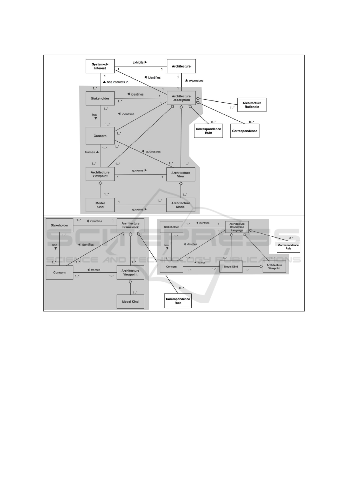
Figure 1: Highlighted Fragments of the ISO 42010 Standard Vocabulary on Architecture Description (AD).
al., 2011), which takes place in the context of a
specific organization or project. The architecture of a
system, within the context of this standard, intends to
convey the essence of a system. The rationale for this
rather broad definition is to capture the underlying
common theme of various existing definitions of
architectures.
The standard also acknowledges that architecting a
system, especially when it is a complex system,
involves multiple Stakeholders that have various
Concerns that are framed by Architecture Viewpoints
and their referenced Model Kinds. An AD contains
instances of those Architecture Viewpoints, called
Architecture Views, which in turn contain instances of
Model Kinds, called Architecture Models.
Furthermore, the ISO 42010 standard specifies
that an AD conforms to a meta (higher level) descript-
tion. This meta description can be an Architecture
Description Language (ADL), shown in Figure 1 (top-
right) or an Architecture Framework (AF), shown in
Figure 1 (bottom-right), which are two widely used
mechanisms to describe architectures. Each mecha-
nism establishes common practices for creating, inter-
preting, analyzing and using ADs within a particular
Reducing UML Modeling Tool Complexity with Architectural Contexts and Viewpoints
131
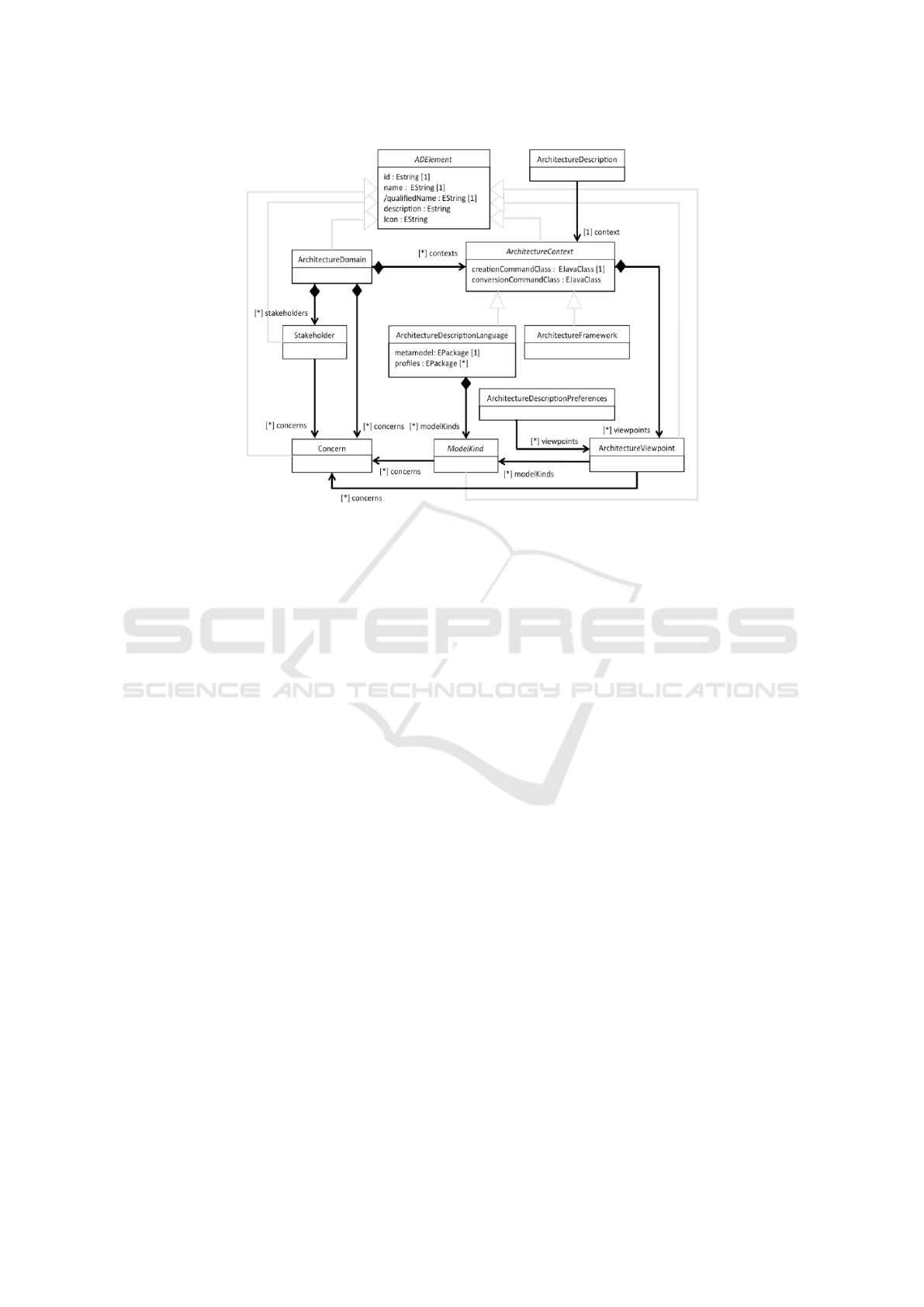
Figure 2: Architecture Metamodel.
domain of application or stakeholder community.
ADL and AF can both contain Architectural
Viewpoints. However, only ADL can contain Model
Kinds, which can be referenced by any viewpoints.
3 ARCHITECTURE
METAMODEL
Our first contribution is adapting the ISO 42010
standard to the context of Model Driven Engineering.
We achieved this by implementing the vocabulary of
the standard as a metamodel (Figure 2). Our approach
employs the metamodel to create architecture models
that govern how UML and other DSML models
represent architecture descriptions.
All elements in an architecture model have types
that extend ADElement in the architecture metamodel.
This type characterizes elements by their unique id,
name, qualified name, optional description and
optional icon. The Architecture Domain type
represents the root of the architecture model. This
type, which is not explicitly defined in the standard,
represents an application domain or a stakeholder
community (e.g., Software Engineering, Systems
Engineering, Automotive, Aerospace). It contains a
set of Stakeholders (e.g., Software Engineers, Systems
Analysts) and Concerns (e.g., Structure, Behavior,
Parametrics). A stakeholder can have concerns from
any domain. A domain also contains a set of
Architecture Contexts. This new type (not in the
standard) is an abstract supertype of both ADL and AF
and represents the context of an Architecture
Description (represented by a UML or a DSML
model). A context specifies a creationCommandClass
and (optionally) a conversionCommandClass that can
be used by a modeling tool to create a new user model
in, or convert an existing user model to, that context
respectively. A context also captures the capability of
both ADLs and AFs to contain Architecture
Viewpoints, which reference a set of Model Kinds. An
ADL specifies a modeling language (e.g., UML,
SysML) by defining its abstract syntax with a
metamodel and an optional set of UML profiles (when
the metamodel is that of UML), and its concrete
syntax, or notation, by a set of Model Kinds (e.g.,
diagrams and tables). An AF, on the other hand,
specifies a modeling methodology that involves
Model Kinds from one or more ADLs.
Notice that a Model Kind is defined as an abstract
metaclass in this metamodel. Instead of predefining
possible representations, we assume that the Model
Kind concept can be specialized to define any kind of
representation and, as discussed later in Section 5, our
implementation allows toolsmiths to define their own.
Two remaining types in the architecture
metamodel, which are Architecture Description and
Architecture Description Preferences, are not meant to
be instantiated within an architecture model, but rather
within a UML or other DSML model that represent an
architecture description. The former references an
Architecture Context that the description conforms to,
and is considered a characteristic of the model. The
MODELSWARD 2018 - 6th International Conference on Model-Driven Engineering and Software Development
132

latter specifies which Architecture Viewpoints are
currently enabled in the description, and is considered
a preference that may be stored in the description
model, to share with all users of the model, or in a
tool’s preference store that belongs to one user or is
shared with a group of users.
4 USING ARCHITECTURE
MODELS TO ADDRESS UML
TOOLING CONCERNS
The architecture models that are discussed in the
previous section allow UML models to specify their
architecture contexts and viewpoints. This can in turn
be leveraged by UML tools to address several
concerns, which is another contribution in this paper.
4.1 Modeling Tool Complexity
One concern is the complexity of the UML tool’s UI.
Typically, UML tools support all or most of the Model
Kinds of UML, which include 14 diagram kinds. More
Model Kinds can be supported for other UML-based
DSMLs. For example, SysML supports 4 more
diagram kinds and two table kinds. Each one of those
Model Kinds supports many types of abstract syntax
(AS) elements. The result is a cluttered UI to account
for this wide range of concepts and modeling
elements.
One strategy that UML tools typically follow to
reduce this clutter is a global setting in the workspace
that controls which subset(s) of those supported
Model Kinds and AS elements are visible. This
approach is not effective since users may be dealing
with multiple kinds of models at the same time, each
may require different subset(s) of UI elements
enabled. However, when UML models specify their
architecture contexts and enabled viewpoints, a tool
can change its UI dynamically for each model by
limiting its options to those suitable for its context and
viewpoints. For example, showing only SysML
diagrams and tables that are supported by the enabled
viewpoints of the SysML context.
4.2 Tool Extensibility Concern
Another tooling concern is the ability to extend UML
architecture contexts or define new contexts by
extending existing ones. For example, some of
SysML’s Model Kinds (e.g., Block Definition
Diagram and Internal Block Diagram) extend
corresponding ones in UML (e.g., Class Diagram and
Composite Structure Diagram), while including others
as is (e.g., State Machine and Activity Diagram).
Without formalisms to specify that, most UML tools
today expose all of their supported Model Kinds.
However, with architecture models, it is
straightforward for an ADL or AF to define
viewpoints that reference Model Kinds from other
ADLs. This allows a tool to only show those Model
Kinds that are supported by the visible viewpoints,
while making them follow the rules of the ADL or AF
in context. For example, the Profile AF has a
viewpoint that includes the UML class diagram but
restrict its elements to only classes, data types,
associations and generalizations.
4.3 Model Migration Across Different
Contexts
A third tooling concern is the need to migrate UML
models from one architecture context to another,
which is usually considered as a refactoring operation.
Without knowing which architecture context a model
belongs to or is migrating to, performing this
refactoring becomes very tricky. However, when a
model references an architecture context A and is
migrating to architecture context B, the latter’s
conversionCommandClass can be instantiated and run
to perform the conversion to B, while taking A into
account. For example, converting a UML model to a
SysML model involves applying the SysML profile,
applying the relevant SysML stereotypes to various
UML elements (e.g., stereotyping all classes with
SysML::Block), and deleting all non-supported
elements (e.g., UML::Component).
4.4 Support for Modeling
Methodologies
A fourth tooling concern is supporting modeling
methodologies. As mentioned earlier, by default,
UML tools either show all their supported capabilities
or allow them to be filtered globally. Unfortunately,
both approaches do not allow a tool to support a
modeling methodology that most often revolves
around defining Model Kinds and grouping them into
viewpoints that address stakeholders’ concerns. With
architecture models, a UML model can specify which
architecture viewpoints, from the selected architecture
context, should be enabled. These could be ones that
frame the concerns of the current stakeholder’s role.
For example, if the stakeholder is a systems analyst
that has a Specifying Requirements concern, then the
Systems Analysis viewpoint, which includes the Use
Reducing UML Modeling Tool Complexity with Architectural Contexts and Viewpoints
133
Case Diagram and the Requirements Diagram, would
be visible. By switching roles or concerns, different
viewpoints will be available and thereby, depending
on the activated viewpoints, different Model Kinds
can be made available. A user may also want to
change the activation of the viewpoints manually to
follow the steps of a methodology.
5 IMPLEMENTATION IN THE
PAPYRUS UML TOOL
We provide a validating of the proposed approach by
implementing it in the Papyrus open-source UML
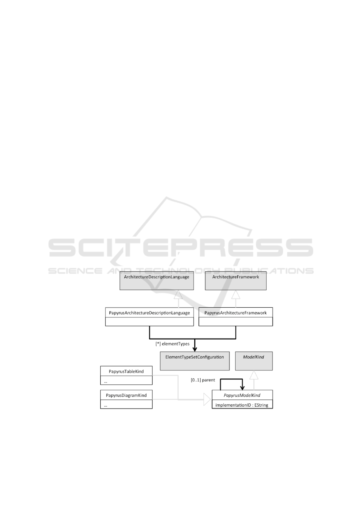
modeling tool. As depicted in Figure 3, the
Architecture metamodel has been extended to
introduce Papyrus-specific concepts and Papyrus’s
Model Kinds.
The Papyrus-specific metamodel includes an
extension to both the ADL and the AF that make them
reference a set of Element Type Set Configurations.
The latter is Papyrus’s model-based mechanism
(details of this mechanism is outside the scope of this
paper) of configuring the editing behavior for abstract
or concrete syntax model elements.
By referencing these configurations from an ADL
or an AF, one can control how UML or DSML models
can be edited in that context. The other extension in
the Papyrus-specific metamodel is for Model Kind.
The Papyrus Model Kind specifies an implementation
id of an underlying model kind (diagram kind or table
kind) that is supported by Papyrus. For example, the
underlying Model Kinds include the 14 UML
diagrams. This type has two subtypes, Papyrus
Diagram Kind and Papyrus Table Kind that specify
how an underlying model kind is customized (the
customization details are beyond the scope of this
paper) in the context of an ADL or AF. For example,
a Package Diagram can be defined as a customization
of the standard UML Class Diagram by limiting the
elements on the diagram to UML Packages. Notice
that a Papyrus Model Kind can also specify another
model kind as its parent to inherit and add to its
customization. For example, the UML Package
Diagram can be a parent to a new version that restricts
the content of the packages to Classes only.
Aside from the extended Architecture metamodel,
we also implemented a mechanism, by which a single
architecture domain can be defined across several
architecture models that might be contributed by
different extensions to Papyrus. To implement this, we
used a composite design pattern. All the Papyrus
tooling used the merged architecture elements from
several architecture models. The merge required that
single valued structural features (e.g., ADElement.id)
have values in only one merge increment (the main
architecture model), while multi-valued structural
features (e.g., ArchitectureDomain. contexts) get their
values aggregated across merge increments.
Figure 3: Papyrus Architecture Metamodel.
MODELSWARD 2018 - 6th International Conference on Model-Driven Engineering and Software Development
134

6 CASE STUDY
Our last contribution is a case study whose objectives
are to a) show that several architecture contexts can be
supported in the same tool (Papyrus in this case)
without cross interference and b) that we can reduce
the complexity of a modeling tool’s UI by dynamically
changing the UI based on a model’s architecture con-
text and enabled viewpoints. In particular, we defined
two architecture models: a) one with one ADL (UML)
and one AF (Profile), and b) one with another ADL
(SysML). Table 1 summarizes the models’ contents.
6.1 Architecture Context Independence
The first objective of the case study is to allow
multiple architecture contexts (UML, SysML, Profile)
to coexist in Papyrus without their contributions
interfering with each other, which was a source of
conflicts in the model editing behavior. Using the new
approach, an architecture context is defined explicitly
in architecture models. These contexts directly
reference their supported model elements (using the
Element Type Set Configurations), which makes it
possible for Papyrus to allow exactly and only those
elements to be used in each context, along with their
supported editing behavior. This makes it easier to
avoid interference, which increase the reliability of the
tool but more importantly let tool smiths design their
own domain specific tooling on top of Papyrus with
no concern for potential conflicts with another
architecture context. In fact, after the integration of
this implementation with Papyrus code base, many
other Papyrus ADLs and AFs were migrated to this
new solution with reports of reduced development
efforts.
6.2 Reducing UI Complexity
The second objective of the case study is to reduce the
complexity (clutter) of the modeling tool’s UI. Much
of this complexity is due to displaying all existing
model contents (abstract and concrete syntax
elements) or potential new contents that can be
Table 1: A Summary of the Case Study Architecture Models.
Context
UML
SysML
Profile
Context Kind
ADL
ADL
AF
Concerns
C1: Functions
C2: Structure
C3: Behavior
C4: Requirements
C5: Parametrics
C6: UML Profiling
Stakeholders
(Concerns)
S1: Software Engineer (C1, C2, C3)
S2: Systems Engineer (C1, C2,
C3, C4, C5)
S3: Domain Architect
(C6)
Model Kinds
M1: Class Diagram
M2: Component Diagram
M3: Deployment Diagram
M4: Inner Class Diagram
M5: Package Diagram
M6: Profile Diagram
M7: Composite Structure Diagram
M8: State Machine Diagram
M9: Sequence Diagram
M10: Activity Diagram
M11: Communication Diagram
M12: Interaction Overview
Diagram
M13: Timing Diagram
M14: Use Case Diagram
M15: Block Definition
Diagram
M16: Internal Block Diagram
M17: Parametrics Diagram
M18: Requirements Diagram
M19: Requirements Table
M20: Allocations Table
Viewpoints
(Model Kinds)
V1: Software Analysis
(M1, M5, M10, M14)
V2: Software Design
(M1-M5, M7-M13)
V3: Systems Analysis
(M15, M5, M14, M18,
M19)
V4: Systems Design
(M15-M17, M20, M4, M5,
M8-M13)
V5: Profile Definition
(M1, M6)
Reducing UML Modeling Tool Complexity with Architectural Contexts and Viewpoints
135

created. For example, the model explorer view
typically shows all existing elements in a model.
Similarly, the explorer provides a context menu that
allows creating all kinds of (abstract syntax and
concrete syntax) elements in a model. Similarly, a
diagram or table editor has a palette and/or a context
menu that allows creating all possible model elements.
The property sheet view also typically displays all
properties of the current selection.
The way to reduce the UI complexity is to remove
irrelevant existing elements (e.g., in the model
explorer) or potential elements (e.g., menu actions to
create new elements) from the UI. Traditionally, there
is no reliable way to check for relevance, since there
is neither explicit context nor any methodological
preferences associated with the model. However, with
our proposed approach, an explicit architecture
context (ADL or AF), as well as a set of
enabled/visible architecture viewpoints, are
referenced by the model. As discussed in section 5, an
architecture context in Papyrus specifies the set of
(abstract syntax) element types that are supported.
This can be used to automatically filter both the set of
existing or potential elements in the model from the
UI. Similarly, architecture viewpoints, and their
Model Kinds, frame stakeholders’ concerns.
Therefore, by identifying the user as one of the
supported stakeholders, the set of existing or potential
Model Kinds that need to be visible can be derived
automatically. Alternatively, a user can choose the set
of enabled viewpoints, which also allows the
calculation of the visible Model Kinds.
Furthermore, when we defined the set of three
architecture contexts in the case study, we achieved
reductions in the number of visible UI items, both
existing and potential. Since the reduction of existing
elements can only have statistical significance when
measured on a set of representative UML or DSML
user models, which we do not have now (we leave it
to future work), we choose to report only on the
reduction of potential elements (i.e., menu actions for
creating new elements). Table 2 shows the number of
menu actions for creating new abstract syntax
elements (e.g., UML elements) and concrete syntax
elements (i.e., diagrams and tables), both before and
after applying our approach, as counted in the context
menu of Papyrus’s model explorer by right clicking
on the root package (different numbers will result
when clicking elsewhere in the hierarchy). For all
architecture contexts, we assume that all their
viewpoints are enabled (further reduction is expected
when some of those views are disabled).
The data in Table 2 suggests that before applying
our approach, the number of abstract syntax element
create actions, which spanned all Packageable
Elements in UML and SysML equaled 88. After
applying our approach, the number is reduced by
~23% for UML, ~14% for SysML (lost the subset of
UML not used in SysML but gained SysML specific
subset), and ~72% for Profile (this is not surprising
given that only a few elements from UML are
needed). The table also suggests that the total number
of concrete syntax elements (Model Kinds) create
actions before our approach was 20 (14 UML
diagrams+4 SysML diagrams+2 SysML tables). After
our approach, the number is reduced by 35% for
UML, 40% for SysML, and 90% for Profile.
Table 2: Number of New Element Actions in Model
Explorer Before and After the New Approach.
UML
SysML
Profile
Abstract Syntax Before
88
88
88
Abstract Syntax After
68
76
25
Concrete Syntax Before
20
20
20
Concrete Syntax After
13
12
2
7 RELATED WORKS
Complexity of UML modeling tools is a recognized
and persistent challenge. The emergence of domain
specific modeling languages and architectural
frameworks means that modern modeling tools must
support broader set of functionalities, and expose even
more elements to users. Petre has conducted a large-
scale study of professional software engineers in 50
companies (Petre, 2013) and reported that modeling
tools complexity is a key impediment. Forward and
Lethbridge surveyed 113 software engineers to
uncover patterns in their modeling practices (Forward
and Lethbridge, 2008). Among their findings, the
tools’ steep learning curve and complexity appear to
limit the adoption of the modeling practice. Baker et
al report on their experience with MDA for over 20
years at Motorola (Baker et al., 2005). They state
multiple positive findings, including improved
software quality and reduced defects rates. However,
they identify key deficiencies in tool support for
different languages and model exchange issues
between development groups using different tools.
Surveying the MDE practices in the Embedded
Systems domain, Liebel et al find that interoperability,
high levels of required training, and usability to be the
biggest shortcomings of all (Liebel et al., 2014).
Education on modeling driven engineering in
software engineering programs seems to also suffer
MODELSWARD 2018 - 6th International Conference on Model-Driven Engineering and Software Development
136

from the complexity of UML tools. One study reports
that industrial-level modeling tools can be used in
education, only if a dedicated and expert tool support
is available (Liebel et al., 2015),a prerequisite not
easily met at many academic institutions. In an
investigation of MDA pedagogies at four higher-level
institutions, students consistently reported that UML,
and its supporting tools, are too complex, and their
associated overhead does not justify the added value
(Badreddin et al., 2015).
Lightweight modeling tools have been developed
to minimize the learning curve and reduce tool
complexity. Examples of such tools include Umple
and TxtUML (Forward et al, 2012) (Devai et al, 2014)
that enable users to create models quickly using
textual editors. Other works proposed a light version
of UML itself (Wrycza and Marcinkowski, 2007).
These approaches do achieve some level of
complexity reduction, but typically at the cost of
compromised functionality.
Existing modeling tools may provide global
preferences or settings to allow users to enable and
disable modeling notations and/or features. This is the
case in Rational Software Architect (Leroux et al.,
2006). These global sittings are not tuned to the
specific model(s) being worked on. Other tools
provide pre-set preferences per role. For example, for
an analyst role, the tool may hide away specific
modeling notations and UI elements.
Architecture description languages and
frameworks have emerged around the same time as
UML. Some of the early ADLs include Rapide
(Lukham et al., 1995), Wright (Allen and Garlen,
1996), and Darwin (Magee et al., 1995).These early
ADLs focused on structural concerns: large-scale
system organization expressed in terms of
components, connectors and configurations and had
varying support for framing behavioral concerns.
More recently, “wide-spectrum” ADLs have been
developed which support a wider range of concerns.
These include Architecture Analysis & Description
Language (AADL) (Fieler et al., 2006), SysML
(Huang et al., 2007), and ArchiMate (Lankhorst et al.,
2009).
In 2000, the Computer Society approved IEEE
Standard 1471(Maier et al.,2001), which established a
consensus on desirable architectural description
practices. Heescha and Hilliard have proposed a
documentation for architecture decision that is based
on ISO 42010 standard (Heesch et al., 2012). This
framework focuses on four viewpoint definitions; a
Decision Detail viewpoint, a Decision Relationship
viewpoint, a Decision Chronology viewpoint, and a
Decision Stakeholder Involvement viewpoint. These
viewpoints definitions satisfy several stakeholder
concerns related to architecture decision management.
Hilliard also published a template that can be used by
architects and organizations to specify architecture
viewpoints in accordance with the ISO 42010 standard
(Hilliard, 2012).
8 CONCLUSION
This paper introduces an approach for reducing the
complexity of modeling tools by leveraging the
concepts of architectural contexts and viewpoints.
This approach is inspired and based on the ISO 42010
standard, which establishes coherent practices for
describing the architecture of large and complex
systems.
This paper makes four contributions; 1)
interpreting and implementing the ISO 42010
standard in the Model Driven Engineering domain
through a new Architecture metamodel that reflects
and refines the vocabulary of the standard; 2) a
demonstration of how the approach addresses several
modeling tools’ concerns including UI complexity,
extensibility to other architecture contexts, model
migration between architecture contexts, and support
of modeling methodologies; 3) a working
implementation of the approach in the Papyrus
modeling tool, and 4) a case study that includes two
architecture models that define three architecture
contexts (UML, SysML, Profile). The case study
demonstrates a) the proposed approach’s
effectiveness in easing the implementation of domain
specific tooling and improving the reliability when
several architecture contexts are supported, and b) the
proposed approach’s ability to reduce UI complexity
by filtering UI items that do not suit the model’s
context and enabled viewpoints.
The proposed approach has the potential to
significantly improve the usability of modeling tools
in general. However, several limitations have been
identified throughout the paper that we plan to address
in future work. One of them is the effort to standardize
the Architecture metamodel at OMG. However, we
will first need to define the Model Kinds in a tool-
neutral way, which would open the door for better
modeling tool interoperability, and improve the users’
experiences across different modeling tools. We also
plan to investigate the limit to which we can automate
model migration between architecture contexts with
more declarative means. We also plan to study the
impact of this approach on reducing the visible details
in user models.
Reducing UML Modeling Tool Complexity with Architectural Contexts and Viewpoints
137

REFERENCES
IEEE, 2008. IEEE Std 1028-2008, IEEE Standard for
Software Reviews and Audits. ISO, May 2011. Systems
and Software Engineering – Architecture Description.
ISO/IEC/IEEE 42010, pp. 1–46.
van Heesch, Uwe, Paris Avgeriou, and Rich Hilliard. "A
documentation framework for architecture decisions."
Journal of Systems and Software 85.4 (2012): 795-820.
Rich Hilliard. Architecture viewpoint template for
ISO/IEC/IEEE 42010. http://www.iso-
architecture.org/42010/templates/, June 2012.
Accessed March, 2017.
Maier, Mark W., David Emery, and Rich Hilliard.
"Software architecture: Introducing IEEE standard
1471." Computer 34.4 (2001): 107-109.
Luckham, D. C., Kenney, J. J., Augustin, L. M., Vera, J.,
Bryan, D., & Mann, W. (1995). Specification and
analysis of system architecture using Rapide. IEEE
Transactions on Software Engineering, 21(4), 336-354.
Allen, R., & Garlan, D. (1996). The Wright architectural
specification language. Rapport technique CMU-CS-
96-TBD, Carnegie Mellon University, School of
Computer Science.
J. Magee, N. Dulay, S. Eisenbach, and J. Kramer,
aSpecifying Distributed Software Architectures,o Proc.
Fifth European Software Eng. Conf. (ESEC '95), Sept.
1995.
Feiler, Peter H., David P. Gluch, and John J. Hudak. The
architecture analysis & design language (AADL): An
introduction. No. CMU/SEI-2006-TN-011. Carnegie-
Mellon Univ Pittsburgh PA Software Engineering Inst,
2006.
Huang, Edward, Randeep Ramamurthy, and Leon F.
McGinnis. "System and simulation modeling using
SysML." Proceedings of the 39th conference on Winter
simulation: 40 years! The best is yet to come. IEEE
Press, 2007.
Lankhorst, Marc M., Henderik Alex Proper, and Henk
Jonkers. "The architecture of the archimate language."
Enterprise, Business-Process and Information Systems
Modeling. Springer Berlin Heidelberg, 2009. 367-380.
Petre, Marian (2013). UML in practice. In: 35th
International Conference on Software Engineering
(ICSE 2013), 18-26 May 2013, San Francisco, CA,
USA, pp. 722–731.
Forward, A., and Lethbridge, T.C. (2008) Problems and
opportunities for model-centric versus code-centric
software development: a survey of software
professionals. Models in Software Engineering
workshop (MiSE ’08) at ICSE, ACM, 27-32.
Taha, S., Radermacher, A., Gérard, S., & Dekeyser, J. L.
(2007, September). MARTE: UML-based Hardware
Design from Modelling to Simulation. In FDL (pp. 274-
279).
Elvesæter, B., Panfilenko, D., Jacobi, S., & Hahn, C. (2010,
October). Aligning business and IT models in service-
oriented architectures using BPMN and SoaML. In
Proceedings of the First International Workshop on
Model-Driven Interoperability (pp. 61-68). ACM.
Hause, Matthew. "The Unified Profile for
DoDAF/MODAF (UPDM) enabling systems of
systems on many levels." Systems Conference, 2010
4th Annual IEEE. IEEE, 2010.
Forward, A., Badreddin, O., Lethbridge, T. C., & Solano, J.
(2012). Model‐driven rapid prototyping with Umple.
Software: Practice and Experience, 42(7), 781-797.
Dévai, G., Kovács, G. F., & An, Á. (2014). Textual,
Executable, Translatable UML. In OCL@ MoDELS
(pp. 3-12).
Wrycza, S., & Marcinkowski, B. (2007). A light version of
UML 2: survey and outcomes. In Proceedings of the
2007 Computer Science and IT Education Conference
(pp. 739-749).
Leroux, Daniel, Martin Nally, and Kenneth Hussey.
"Rational Software Architect: A tool for domain-
specific modeling." IBM systems journal 45.3 (2006):
555-568.
Baker, Paul, Shiou Loh, and Frank Weil. "Model-Driven
engineering in a large industrial context—motorola
case study." International Conference on Model Driven
Engineering Languages and Systems. Springer Berlin
Heidelberg, 2005.
Liebel, Grischa, et al. "Assessing the state-of-practice of
model-based engineering in the embedded systems
domain." International Conference on Model Driven
Engineering Languages and Systems. Springer
International Publishing, 2014.
Badreddin, O.B., Sturm, A., Hamou-Lhadj, A., Lethbridge,
T., Dixon, W. and Simmons, R., 2015. The Effects of
Education on Students' Perception of Modeling in
Software Engineering. In HuFaMo@ MoDELS (pp.
39-46).
Liebel, Grischa, Rogardt Heldal, Jan-Philipp Steghöfer, and
Michel RV Chaudron. "Ready for Prime Time,-Yes,
Industrial-Grade Modelling Tools can be Used in
Education." (2015)
MODELSWARD 2018 - 6th International Conference on Model-Driven Engineering and Software Development
138
