
Optimized KinectFusion Algorithm
for 3D Scanning Applications
Faraj Alhwarin, Stefan Schiffer, Alexander Ferrein and Ingrid Scholl
Mobile Autonomous Systems & Cognitive Robotics Institute (MASCOR),
FH Aachen University of Applied Sciences, Aachen, Germany
Keywords:
Optimized KinectFusion, Body Scanner, 3D Reconstruction.
Abstract:
KinectFusion is an effective way to reconstruct indoor scenes. It takes a depth image stream and uses the
iterative closests point (ICP) method to estimate the camera motion. Then it merges the images in a volume
to construct a 3D model. The model accuracy is not satisfactory for certain applications such as scanning a
human body to provide information about bone structure health. For one reason, camera noise and noise in
the ICP method limit the accuracy. For another, the error in estimating the global camera poses accumulates.
In this paper, we present a method to optimize KinectFusion for 3D scanning in the above scenarios. We aim
to reduce the noise influence on camera pose tracking. The idea is as follows: in our application scenarios we
can always assume that either the camera rotates around the object to be scanned or that the object rotates in
front of the camera. In both cases, the relative camera/object pose is located on a 3D-circle. Therefore, camera
motion can be described as a rotation around a fixed axis passing through a fixed point. Since the axis and the
center of rotation are always fixed, the error averaging principle can be utilized to reduce the noise impact and
hence to enhance the 3D model accuracy of scanned object.
1 INTRODUCTION
3D reconstruction is one of the most fundamental is-
sues in computer vision, which has many practical ap-
plications in a range of fields such as robotics, virtual
reality, video games and 3D scanning. To reconstruct
a scene, a sequence of images captured at different
viewpoints or a video is usually required. Generally,
for visual 3D reconstruction, two problems have to be
solved: (1) camera motion tracking and (2) depth re-
covery from 2D images. For camera tracking, the ca-
mera has to move slightly over time or its frame-rate
has to be sufficient, so that successive images over-
lap. The relative camera motion from frame to frame
can then be computed by feature extraction and mat-
ching. This technique is known as Structure from Mo-
tion (SfM) (Changchang, 2013; Moulon et al., 2013).
For scene depth recovery from 2D images, the scene
has to be viewed from at least two known viewpoints.
Stereo correspondences can then be used for depth
estimation using epipolar geometry and stereo trian-
gulation. This technique is called Multi view Stereo
(MVS) (Furukawa and Ponce, 2007; Hern
´
andez et al.,
2007).
By combining SfM and MVS, visual 3D recon-
struction can be realized. Once the camera motion
is estimated, recovered depth frames are transformed
according to their corresponding camera poses and
combined together or merged into a common 3D vo-
lume to generate a 3D model of the scene. For camera
motion refinement, bundle adjustment or pose graph
optimization are usually used (Ni et al., 2007; Yu and
Zhang, 2016).
According to feature density used for camera
tracking and depth recovering, 3D reconstruction
methods can be classified into two major categories:
sparse and dense reconstruction. By sparse recon-
struction, the camera motion as well as scene depth
are estimated by matching sparse local features ex-
tracted from the images. The accuracy of camera
tracking is strongly dependent on the texture content
of the scene. In addition, the generated model is in-
complete and its quality is poor because only depths
of sparsely distributed features are used. Although
sparse methods such as monocular SLAM (Schoeps
et al., 2014; Davison et al., 2007) are successfully
used in robotics, e.g. for self-localisation and map-
ping, they are totally unsuitable for 3D scanning ap-
plications. With dense approaches, sparse features are
first used to estimate initial camera motion. Then the
depth of all image points computed by stereo vision
(Negre et al., 2016; Engel et al., 2015) or provided by
50
Alhwarin, F., Schiffer, S., Ferrein, A. and Scholl, I.
Optimized KinectFusion Algor ithm for 3D Scanning Applications.
DOI: 10.5220/0006594700500057
In Proceedings of the 11th International Joint Conference on Biomedical Engineer ing Systems and Technologies (BIOSTEC 2018) - Volume 2: BIOIMAGING, pages 50-57
ISBN: 978-989-758-278-3
Copyright © 2018 by SCITEPRESS – Science and Technology Publications, Lda. All rights reserved

a depth sensor like the Microsoft Kinect (Kerl et al.,
2013; Fioraio and Stefano, 2014) are used to refine
camera poses. While the scene can be reconstructed
completely with dense approaches, the accuracy of re-
constructed model is insufficient for 3D body scan-
ning and the run time is extremely expensive.
Using KinectFusion method (Newcombe et al.,
2011), it is possible to determine camera motion from
depth images of a Kinect sensor of Microsoft in real
time and simultaneously to create a 3D model of the
scene by integrating depth information into a trunca-
ted signed distance function (TSDF) volume. Using
the Iterative Closest Point (ICP) method, correspon-
dences in 3D point clouds are found and used for
camera motion tracking. In contrast to other 3D re-
construction methods that track camera movement
from frame to frame, KinectFusion tracks camera mo-
tion from frame to model increasing the reliability of
tracking, since depth noise is reduced while recon-
structing model by averaging of all previous depth
frames. In KinectFusion, finding correspondences,
estimating camera motion and generating 3D mo-
del can be parallelized efficiently on GPU hardware,
which makes it real-time adaptable.
Generally, KinectFusion has two main drawbacks.
The first one is that the reconstruction fails if the scene
has no distinctive shapes, for example, when the ca-
mera moves parallel to a plane or rotates around cylin-
drical or spherical surface. In such cases, KinectFu-
sion can not track the camera motion correctly. This
problem can be faced by human body scanning appli-
cations for medical purpose, where many parts of na-
ked human body are approximately cylindrical such
as legs and the torso. The second drawback is that the
depth data provided by the Kinect sensor involve er-
ror in a range of ±5mm. In camera motion tracking
this error causes small local drifts that are accumu-
lated over time. This in turn leads to unacceptable
deformations in the resulting 3D model.
Recently, many improvements of KinectFusion
method have been proposed. (Jia et al., 2016)
improved KinectFusion by adding graph based-
optimization to achieve rapid optimization of error
accumulation. (Afzal et al., 2014) proposed a modifi-
cation of KinectFusion to enhance 3D reconstruction
of non-rigidly deforming objects. (Kainz et al., 2012)
improved the KinectFusion algorithm to allow for
3D reconstruction from multiple sensors simultane-
ously. (Whelan et al., 2012) extended the KinectFu-
sion method by visual odometry to avoid camera mo-
tion tracking failure at regions of low geometric fea-
tures. (Pagliari et al., 2014) proposed an improvement
of KinectFusion by executing the scanning process
twice. In the first run, an average circular trajectory
of the camera is estimated. In the second run, the tra-
jectory is used for depth data correction.
In this paper, we present a new method to opti-
mize KinectFusion for a 3D body scanner. The idea
is based on the assumption that, for most 3D scan-
ning applications, the camera rotates about the object
to be scanned or the object rotates in front of the ca-
mera. In both cases, the rotation axis and the rota-
tion center remain unchanged while scanning. The-
refore, the camera motion tracking can be simplified
by estimating a rotation angle instead of estimating a
6 DoF transformation. The rotation axis and center
are determined accurately by averaging of depth er-
rors. Performing camera motion tracking using our
method improves the quality of reconstructed 3D mo-
del for two reasons. For one, only angle errors are
accumulated, instead of accumulating transformation
drifts. For another, reducing correspondence search
to only one dimension removes many outliers. The
rest of paper is organized as follows. In Section 2 the
KinectFusion method is described briefly. In Section
3, our method is presented in detail. Experimental
results are evaluated in Section 4. Finally, the paper
concludes in Section 5.
2 KINECT FUSION ALGORITHM
KinectFusion (Newcombe et al., 2011; Izadi et al.,
2011) is a powerful 3D reconstruction technique ba-
sed on Microsoft Kinect Sensor. It allows the 3D
reconstruction of an indoor scene through moving a
kinect camera around in real-time using commodity
graphics hardware. It integrates and merges consecu-
tive depth images provided by the Kinect depth sen-
sor in a 3D volumetric data structure, assuming the
relative position between the sensor and the object is
only slightly changed over time. As described in (Ne-
wcombe et al., 2011), KinectFusion consists of four
major stages: surface measurements, surface recon-
struction update, surface prediction and sensor pose
estimation. In the surface measurement stage the ver-
tex and normal maps are computed from the depth
image and the camera’s intrinsic parameters. Be-
fore computing vertex and normal maps, depth ima-
ges are filtered using bilateral filter to reduce depth
noise while keeping depth edges unblurred as much
as possible. In the surface reconstruction update,
the surface measurements computed in the previous
stage are transformed according to a global coordi-
nate frame and integrated into a 3D volumetric data
structure called Truncated Signed Distance Function
(TSDF). For sensor pose estimation, it is assumed
that only a small camera motion occurs from one
Optimized KinectFusion Algorithm for 3D Scanning Applications
51

frame to the next. This allows the use of a fast pro-
jective data association algorithm (Arya et al., 1995)
to obtain correspondence points and the point-plane
metric (Yang and Gerard, 1992) for sensor pose esti-
mation.
3 OPTIMIZED KINECT FUSION
As mentioned above, in our target applications for 3D
scanning, the camera usually rotates around the ob-
ject to be scanned or the object rotates in front of the
camera. In both cases the relative object/camera mo-
tion trajectory is described as a three-dimensional ci-
rcle. Therefore, the camera pose is always described
as a rotation by a variable angle (rotation angle) about
a fixed axis (rotation axis) passing through a fixed
point (rotation center). In KinectFusion, the Iterative
Closest Points (ICP) method is used to estimate the
transformation between each successive depth ima-
ges (the current depth image and a ray-casted depth
image from the live reconstructed 3D model from all
previous depth images). The transformation consists
of six parameters, three for the rotation and three for
the translation. Since the depth data is noisy, this will
affect all transformation parameters. In our proposed
method, in order to reduce the noise effect on the esti-
mated transformation as much as possible, the trans-
formation is separated into three components: (1) the
axis, (2) the center and (3) the angle of rotation. Since
the axis and the center of rotation are fixed for all ca-
mera poses, they can be estimated offline and error
averaging can be applied to reduce depth noise effects
on them significantly. Through this idea, the effect of
noise is only limited to the rotation angle, rather than
affecting all the transformation parameters, which al-
lows to reduce the error of camera motion estimation
and to increase the quality of the generated 3D mo-
del. For this purpose we must firstly determine the
axis and the center of rotation with a reasonable accu-
racy. Then we use the ICP method to estimate only
the rotation angle between successive camera frames.
The determination of rotation axis and center is only
needed once, as long as the set-up of the scanner is
not changed.
3.1 Determination of Rotation Axis and
Center
To determine the axis and center of rotation while
reducing the noise effect on them, a sphere with a
known radius and a specific color is used. We rotate
the sphere in front of the kinect camera and estimate
the sphere centers in the successive camera frames.
From each depth image and its corresponding color
image, a colored point cloud is computed. Color-
based segmentation is used to segment the point cloud
keeping only points lying on the sphere. A spherical
surface with a certain radius is then fitted to the re-
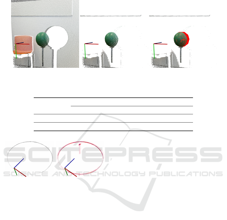
maining points. Figure 1 shows the input point cloud,
the color-based segmented point cloud, and the fitted
spherical surface.
In the ideal case, these sphere centers should all
fall on a 3D circle, but because of depth noise, a cir-
cular point cloud is obtained as shown in Figure 2(a).
Using the Random Sample Consensus (RANSAC)
method, several circles can be fitted to this point
cloud. The error can be averaged over all these cir-
cles by computing the mean circle. The mean circle
axis and center represent the rotation axis and center
of the scanner. Figure 2(b) shows a range of circles
fitted to center cloud and the computed mean circle.
Table 1 shows the mean values of the rotation
axis and center and their standard deviations. Once
the rotation axis and center of the scanner are known,
camera motion estimation can be reduced to estimate
only one parameter (i.e. the rotation angle) rather than
estimating 6 DoF transformation, as the case of Ki-
nectFusion. For this purpose, in the next section, we
will modify camera tracking stage of KinectFusion ta-
king into account that the axis and center of rotation
are previously known.
3.2 Rotation Angle Estimation
Assuming that the camera pose at any time is given
by a rotation about a known axis passing through a
known point. Hence, the rotation matrix and transla-
tion vector are given as:
R =
r
2
1
.q + c r
1
r
2
.q − r
3
.s r
1
r
3
.q + r
2
.s
r
1
r
2
.q + r
3
.s r
2
2
.q + c r
2
r
3
.q − r
1
.s
r
1
r
3
.q − r
2
.s r
2
r
3
.q + r
1
.s r
2
3
.q + c
t = o − R · o
(1)
where c = cosα, s = sinα, q = (1 − cosα), r =
[r
1
,r
2
,r
3
]
T
is normalized rotation axis, and o =
[o
1
,o
2
,o
3
]
T
is rotation center. This transformation
maps any 3D point p
k
c
in camera frame at time k to
its corresponding point p
k
g
in global coordinate frame.
p
k
g
= R · p
k
c
+t = R · (p
k
c
− o) + o (2)
By substituting Equation 1 in Equation 2 and re-
arranging we get
p
k
g
= A
k
g
· cosα + B
k
g
· sinα +C
k
g
(3)
BIOIMAGING 2018 - 5th International Conference on Bioimaging
52
(a) (b) (c)
Figure 1: Computation sphere center: (a)input point cloud, (b)color-based segmented point cloud and (c) spherical surface
fitted to segmented point cloud.
Table 1: mean values and standard deviations of averaged 3D circles.
Averaged circle Circle axis Circle center
x y z x y z
mean value 0.4964 0.5852 0.6359 -0.0232 0.9986 -0.0463
std deviation 0.0046 0.0017 0.0049 0.0048 0.0002 0.0051
(a) (b)
Figure 2: (a) Sphere centers obtained while moving it in
front of the kinect sensor represented as pointcloud and (b)
some fitted circles using RANSAC and their axes represen-
ted as arrows (red circles) and mean circle (blue).
where
A
k
g
= (I
3x3
− rr
T
)(p
k
c
− o)
B
k
g
= [r]
x
(p
k
c
− o)
C
k
g
= rr
T
(p
k
c
− o) + o
with
[r]
x
=
0 −r
3
r
2
r
3
0 −r
1
−r
2
r
1
0
As in KinectFusion, for camera motion tracking we
use the projective data association method to detect
correspondences points and the point-plane error me-
tric for camera pose estimation. Utilising the ver-
tex and normal maps computed from current depth
frame and the depth frame ray-casted from TSDF
volume, the current camera pose can be estima-
ted by minimizing the following point-plane energy
function(Newcombe et al., 2011).
E(α) =
∑
u
h
(p
k
g
(u) − ˆq
k−1
g
( ˆu)) ˆn
k−1
g
( ˆu)
i
2
(4)
where p
k
g
(u) are 3D points at xy-position u sensed
by camera at time k and transformed to global frame,
ˆq
k−1
g
( ˆu) and ˆn
k−1
g
( ˆu) are corresponding 3D points and
its normals predicted from the 3D model at time k-
1. To reduce outliers, two constraints are considered:
Firstly, correct correspondences must have the same
distance to the rotation center.
(p
k
g
(u) − o)
2
−
ˆq
k−1
g
( ˆu) − o
2
<= T hr
1
and secondly, correct correspondences must lie on the
same plane perpendicular to the rotation axis.
(p
k
g
(u) − ˆq
k−1
g
( ˆu)) · r <= T hr
2
Only correspondences that meet these two condi-
tions are taken into consideration while computing the
objective function E(α).
By substituting Equation 3 in Equation 4 we get
E(α) =
∑
u
[(a · cosα + b · sinα + c)]
2
(5)
where
n = ˆn
k−1
g
( ˆu)
a = (A
k
g
)
T
· n
b = (B
k
g
)
T
· n
c = (C
k
g
− ˆq
k−1
g
( ˆu))
T
· n
Optimized KinectFusion Algorithm for 3D Scanning Applications
53
By expanding Equation 5 we can get
E(α) = cos
2
α ·
∑
a
2
+ sin
2
α ·
∑
b
2
+
∑
c
2
+ 2cosαsinα ·
∑
ab
+2sinα ·
∑
bc + 2cosα ·
∑
ac
(6)
By computing the derivative of the function E(α)
with respect to α and setting to zero, we get
f (α) =
dE(α)
dα
= sin(2α) · (
∑
b
2
−
∑
a
2
)
+2cos(2α) ·
∑
ab+
2cos(α) ·
∑
bc − 2sin(α) ·
∑
ac
= 0
(7)
The summands in Equation 7 are computed on
GPU using a parallel tree-based reduction (Harris
et al., 2007). By solving Equation 7 we get the ro-
tation angle that minimizes the point to plane metric.
To solve this equation, we use the Newton-Raphson
method.
α
k
= α
k−1
− f (α
k−1
)/ f
0
(α
k−1
) (8)
Assuming angle between each two successive camera
frames is small, choosing α
0
= 0 is a good start for
rapid convergence of the solution.
4 EXPERIMENTAL RESULTS
In order to evaluate the performance of our propo-
sed method, we conducted some comparative ex-
periments in regards to the standard KinectFusion.
In these experiments we used the open source im-
plementation of KinectFusion provided in the Point
Cloud Library (PCL) called KinFu. In our implemen-
tation, we used KinFu code as a base and modified it
according to our proposed idea explained in Section 3
above. To access the depth data generated by the Ki-
nect v2 camera, the iai − kinect2 (Wiedemeyer, 2015)
was used. The iai− kinect2 is a software wrapper that
bridges the open source driver libreenect2 for Kinect
v2 devices with Robot Operating System (ROS) and
involves tools for camera calibration and registration.
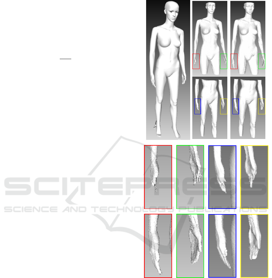
In the first experiment, we used a display dummy,
that simulates a human body. The dummy was scan-
ned with Comet L3D scanner with resolution of 0.1
mm and the created 3D model (shown in Figure
3(a))is used as a ground truth.
The scanning was realized by rotating the dummy in
front of kinect camera using a turntable. To com-
pare our method to KinectFusion, the depth frames
are stored while scanning, and used offline to recon-
struct 3D meshes using standard KinFu and our op-
timized KinFu. The obtained meshes are presented
(a) (b) (c)
(d)
(e)
Figure 3: 3D models of the display dummy used in our ex-
periments. (a) model of the dummy scanned by laser scan-
ner and used as ground truth. (b) model of dummy scanned
with standard KinectFusion. (c) model of dummy scanned
with our optimized KinectFusion (d) zoom of some parts in
standard KinectFusion meshes. (e) zoom of the same parts
in optimized KinectFusion meshes.
in Figures 3(b) and 3(c). We found that the quality of
meshes reconstructed by our method are always better
than the meshes of standard KinFu. As shown in Fi-
gure 3(d), some parts (such as hands) are deformed in
KinFu meshes, while they are reconstructed correctly
in optimized meshes(see Figure 3(e)).
BIOIMAGING 2018 - 5th International Conference on Bioimaging
54
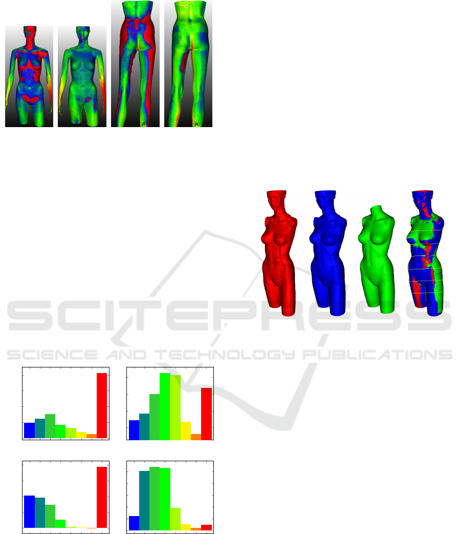
(a) (b) (c) (d)
Figure 4: The point to point comparison between ground
truth mesh and KinFu meshes (a)+(c) and optimized KinFu
mesh (b)+(d), visualized by color scale.
To compare meshes quantitatively, the point to
point distances between obtained meshes and ground
truth mesh are computed using CloudCompare soft-
ware (Girardeau-Montaut, 2014). The distances are
visualized as color scale ranging from blue (<-5mm)
via green (0mm) to red (>5mm) in Figure 4 and repre-
sented as histograms in Figure 5. As evident from the
histograms, our method outperforms the standard Ki-
nectFusion. For our meshes more than 80% of point
distances are lying within the range ± 5mm, whereas
for the original KinFu meshes only less than 50% are
lying in the same range. In the Figures 4(a, b) and
first row of Figures 5, it shown that many points have
distances larger than 5mm. The reason of that is be-
cause the arms of the dummy are movable and differ
from the ground truth model.
[<-5]
[-5,-3]
[-3,-2]
[-2,0]
[0,2]
[2,3]
[3,5]
[>5]
0
10
20
30
40
PDF(%)
[<-5]
[-5,-3]
[-3,-2]
[-2,0]
[0,2]
[2,3]
[3,5]
[>5]
5
10
15
20
PDF(%)
[<-5]
[-5,-3]
[-3,-2]
[-2,0]
[0,2]
[2,3]
[3,5]
[>5]
0
10
20
30
40
Approximate distance(mm)
PDF(%)
[<-5]
[-5,-3]
[-3,-2]
[-2,0]
[0,2]
[2,3]
[3,5]
[>5]
0
5
10
15
20
25
Approximate distance(mm)
PDF(%)
(a) (b)
Figure 5: Distance histograms for standard KinFu meshes
(a) and optimized KinFu meshes (b).
During our experiments, we found that standard
KinectFusion always deforms the model of scanned
object by down-scaling it non-linearly. The same re-
sult was found in (Pagliari et al., 2014), where they in-
terpreted it as a cause of focal length error of the depth
sensor. In this paper, we found that the reason of do-
wnscaling is due to the accumulation of depth data
errors. Using our optimization we reduced this effect
significantly as shown in Fig. 6 and Fig. 7. In Figure 6
meshes are reconstructed from the same depth frame
sequence and at the same fusion parameters (voxel
grid size, truncated threshold and etc) using standard
and optimized KinFu. Meshes are then registered to a
ground truth mesh and some slices are taken to show
scaling effect. Figure 7 shows the 2D views of the
slices visible as thin yellow boxes in Figure 6(d). As
evident from the slices shown in Figure 7 it is clear
that the optimized mesh is closer to the ground truth
mesh than the standard KinFu mesh.
(a) (b) (c) (d)
Figure 6: Reconstructed meshes comparison: (a) standard
KinFu, (b) optimized KinFu, (c) ground truth meshes, (d)
registered meshes and positions of some slices taken to
show scaling effect.
In the second experiment, optimized KinFu is
compared to standard KinFu for objects with high ge-
ometric shapes. In this experiment we used a styropor
box with high geometric details as showm in Figure 8.
While rotating the box in front of the camera using a
turntable the depth frames are stored and then used to
reconstruct a 3D model of the box using standard and
optimized KinFu. As shown in Figure 8, the quality of
the optimized KinFu mesh outperforms the quality of
KinFu mesh. By comparing the second and the third
row in Figure 8, it is clear that many fine details have
been preserved in our optimized mesh, while they are
blurred in the other mesh.
5 CONCLUSIONS
In this paper, we have presented a method to optimize
KinectFusion method for 3D body scanning, where
camera pose is described as a rotation about fixed
axis passing through a fixed point. The camera mo-
tion tracking was split into two stages, the first one is
Optimized KinectFusion Algorithm for 3D Scanning Applications
55
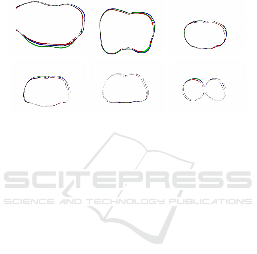
(a) Slice 1 (b) Slice 2 (c) Slice 3
(d) Slice 4 (e) Slice 5 (f) Slice 6
Figure 7: 2D views of slices from Fig 6(d): green shows ground truth, red shows standard KinFu, and blue shows optimized
KinFu.
offline determining of rotation axis and center while
reducing errors by noise averaging technique. The se-
cond one performs camera motion tracking limited to
estimate only a rotation angle instead of estimating a
complete 6 DoF transformation. Noise averaging in
the first stage, and correspondence outliers removing
through motion tracking limitation to on-dimensional
in the second stage enhanced the quality of generated
3D model significantly as shown in the experimental
results.
ACKNOWLEDGEMENTS
This work was supported by the German Federal
Ministry of Education and Research (BMBF) under
grant No. 03FH053PX5.
REFERENCES
Afzal, H., Ismaeil, K., Aouada, D., Destelle, F., Mirbach,
B., and Ottersten, B. (2014). Kinect Deform: Enhan-
ced 3D reconstruction of non-rigidly deforming ob-
jects. In 3DV (Workshops), pages 7–13. IEEE.
Arya, S., Mount, D. M., Netanyahu, N. S., Silverman,
R., and Wu, A. Y. (1995). Registering multiview
range data to create 3D computer objects. IEEE Tran-
sactions on Pattern Analysis and Machine Intelligence
(PAMI), 17(8):820–824.
Changchang, W. (2013). Towards linear-time incremental
structure from motion. In 3DTV-Conference, 2013 In-
ternational Conference on, pages 127–134. IEEE.
Davison, A., Reid, I. D., Molton, N., and Stasse, O.
(2007). MonoSLAM: Real-Time Single Camera
SLAM. IEEE Trans. Pattern Anal. Mach. Intell.,
29(6):1052–1067.
Engel, J., St
¨
uckler, J., and Cremers, D. (2015). Large-scale
direct SLAM with stereo cameras. In In Proceedings
of the IEEE International Conference on Intelligent
Robots and Systems (IROS).
Fioraio, N. and Stefano, D. L. (2014). SlamDunk: afforda-
ble real-time RGB-D SLAM. In Workshop at the Eu-
ropean Conference on Computer Vision, pages 401–
414. Springer.
Furukawa, Y. and Ponce, J. (2007). Accurate, dense, and ro-
bust multi-view stereopsis. In CVPR. IEEE Computer
Society.
Girardeau-Montaut, D. (2014). Cloudcompare.
Harris, M., Sengupta, S., and Owens, J. (2007). Parallel
prefix sum (scan) with CUDA. In Nguyen and Hubert,
editors, GPU Gems 3, chapter 39, pages 851–876. Ad-
dison Wesley.
Hern
´
andez, C., Vogiatzis, G., and Cipolla, R. (2007). Pro-
babilistic visibility for multi-view stereo. In CVPR.
IEEE Computer Society.
Izadi, S., Kim, D., Hilliges, O., Molyneaux, D., Newcombe,
R., Kohli, P., Shotton, J., Hodges, S., Freeman, D.,
Davison, A., and Fitzgibbon, A. (2011). Kinectfusion:
real-time 3D reconstruction and interaction using a
moving depth camera. In In Proc. UIST, pages 559–
568.
Jia, S., Li, B., Zhang, G., and Li, X. (2016). Improved
kinectfusion based on graph-based optimization and
large loop model. In IEEE International Conference
on Information and Automation (ICIA)).
Kainz, B., Hauswiesner, S., Reitmayr, G., Steinberger, M.,
Grasset, R., Gruber, L., Veas, E. E., Kalkofen, D.,
Seichter, H., and Schmalstieg, D. (2012). OmniKi-
BIOIMAGING 2018 - 5th International Conference on Bioimaging
56
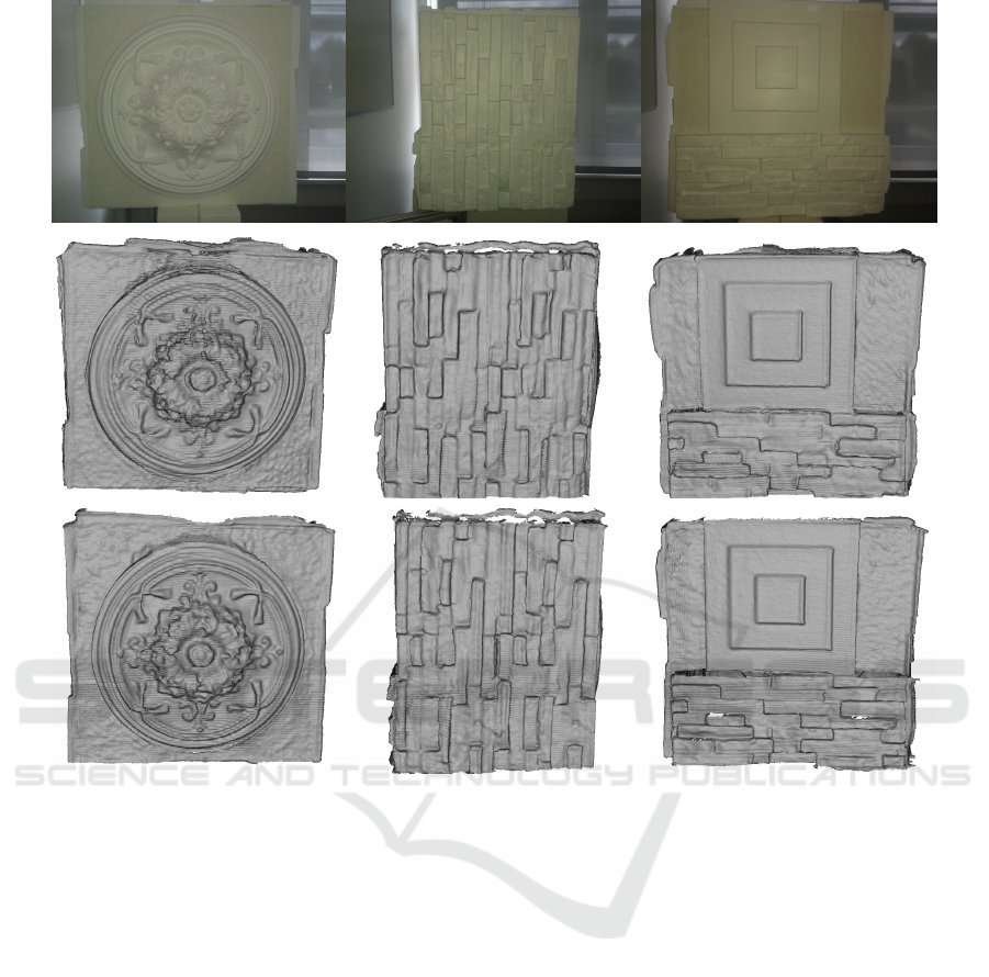
Figure 8: Comparison between standard and optimized KinFu for objects with high geometric features. First row: RGB
images of 3 different sides of a box. Second row: box mesh reconstructed by KinFu. Third row: the same mesh reconstructed
by optimized KinFu.
nect: real-time dense volumetric data acquisition and
applications. In VRST, pages 25–32. ACM.
Kerl, C., Sturm, J., and Cremers, D. (2013). Dense visual
SLAM for RGB-D cameras. In Proc. of the Int. Conf.
on Intelligent Robot Systems (IROS).
Moulon, P., Monasse, P., and Marlet, R. (2013). Global fu-
sion of relative motions for robust, accurate and scala-
ble structure from motion. In Proc. ICCV. IEEE.
Negre, P. L., Bonin-Font, F., and Oliver, G. (2016). Cluster-
based loop closing detection for underwater SLAM
in feature-poor regions. In 2016 IEEE International
Conference on Robotics and Automation (ICRA), pa-
ges 2589–2595.
Newcombe, R., Izadi, S., Hilliges, O., Molyneaux, D., Kim,
D., Davison, A., Kohli, P., Shotton, J., Hodges, S.,
and Fitzgibbon, A. (2011). Kinectfusion: Real-time
dense surface mapping and tracking. In Proc. IEEE
Int. Symp. Mixed and Augm. Reality. IEEE.
Ni, K., Steedly, D., and Dellaert, F. (2007). Out-of-
core bundle adjustment for large-scale 3D recon-
struction. In International Conference on Computer
Vision (ICCV).
Pagliari, D., Menna, F., Roncella, R., Remondino, F., and
Pinto, L. (2014). Kinect fusion improvement using
depth camera calibration. In the Technical Commis-
sion V Symposium Remote Sensing Spatial and Infor-
mation Science, pages 23–25.
Schoeps, T., Engel, J., and Cremers, D. (2014). Semi-dense
visual odometry for AR on a smartphone. In ismar.
Whelan, T., Kaess, M., Fallon, M., Johannsson, H., Leo-
nard, J., and McDonald, J. (2012). Kintinuous: Spati-
ally extended kinectfusion. In RSS Workshop on RGB-
D: Advanced Reasoning with Depth Cameras, Syd-
ney, Australia.
Wiedemeyer, T. (2014–2015). Iai kinect2. Accessed June
12, 2015.
Yang, C. and Gerard, M. (1992). Object modelling by regis-
tration of multiple range images. Image Vision Com-
put., 10(3):145–155.
Yu, W. and Zhang, H. (2016). 3D Reconstruction of Indoor
Scenes Based on Feature and Graph Optimization. In
International Conference on Virtual Reality and Visu-
alization (ICVRV). IEEE.
Optimized KinectFusion Algorithm for 3D Scanning Applications
57
