
Managing Variability in Models and Derived Artefacts in Model-driven
Software Product Lines
Thomas Buchmann and Sandra Greiner
Chair of Applied Computer Science I, University of Bayreuth, Universit
¨
atsstrasse 30, 95440 Bayreuth, Germany
Keywords:
Model-driven Development, Software Product Lines, Feature Annotations, Variability, Feature Propagation.
Abstract:
Software product line engineering aims at automatically deriving a family of software products from a common
platform. Model-driven software engineering emphasizes using models as primary development artefacts. In
many cases, the static structure of a software system can be automatically generated from static models such as
class diagrams. However, hand-written source code is still necessary, either for specifying method bodies or for
integrating the generated code with already existing artefacts or frameworks. This fact causes problems when
developing software product lines in a model-driven way: Variability information needs to be kept consistent
over a series of heterogeneous artefacts, including models and generated as well as hand-written source code.
In this paper, we present a concept and the corresponding technical solution, which allows for managing
variability in models and corresponding derived artefacts. We demonstrate the feasibility of our approach with
the help of a concrete use case in the context of models and hand-written source code fragments.
1 INTRODUCTION
Model-Driven Software Engineering (MDSE) (V
¨
olter
et al., 2006) is a discipline which receives increasing
attention in both research and practice. It puts strong
emphasis on the development of high-level models
rather than on the source code. Models are not con-
sidered as documentation or as informal guidelines
how to program the actual system. In contrast, mod-
els have well-defined syntax and semantics. More-
over, MDSE aims at the development of executable
models. The resulting models are then transformed in
a series of subsequent transformation steps (Frankel,
2003) into source code which can be compiled and
executed on the respective target platform.
Ideally, software engineers operate only on the
level of executable models such that there is no need
to inspect or edit the actual source code (if any). In
this sense, models are the code (now written in a high-
level modeling language). However, practical experi-
ences have shown that language-specific adaptations
to the generated source code are frequently necessary.
Object-oriented modeling is centered around class
diagrams, which constitute the core model for the
structure of a software system. From class dia-
grams, parts of the application code may be gener-
ated, including method bodies for elementary oper-
ations such as creation/deletion of objects and links,
and modifications of attribute values. However, for
user-defined operations only methods with empty
bodies may be generated which have to be filled in
by the programmer.
The Eclipse Modeling Framework (EMF) (Stein-
berg et al., 2009) has been established as an extensible
platform for the development of MDSE applications.
It is based on the Ecore meta model which is com-
patible with the OMG Meta Object Facility (MOF)
specification (OMG, 2015). In EMF, for instance,
only structure is modeled by means of class diagrams,
whereas behavior is described by modifications to the
generated source code. However, EMF is already
tuned for efficient programming, as it demands for
hand-written Java code for method bodies. Users are
able to annotate the respective parts and the Eclipse
Modeling Framework uses a code-merging generator
to preserve these fragments on subsequent code gen-
eration steps.
Software product line engineering (SPLE)
(Clements and Northrop, 2001) deals with the
systematic development of products belonging to
a common system family. Rather than developing
each instance of a product line from scratch, reusable
software artefacts are created such that each product
may be composed of a collection of those artefacts –
the platform. A variability model is used to capture
commonalities and differences among different
326
Buchmann, T. and Greiner, S.
Managing Variability in Models and Derived Artefacts in Model-driven Software Product Lines.
DOI: 10.5220/0006563403260335
In Proceedings of the 6th International Conference on Model-Driven Engineering and Software Development (MODELSWARD 2018), pages 326-335
ISBN: 978-989-758-283-7
Copyright © 2018 by SCITEPRESS – Science and Technology Publications, Lda. All rights reserved

products. Feature models (Kang et al., 1990) are
used to capture the commonalities and differences
of members of a product line, while feature con-
figurations describe the characteristics of a specific
member thereof. Software product line engineering
is divided into two levels. (1) Domain engineering
is used to analyze the domain and capture the
commonalities and variabilities in a feature model.
Furthermore, the features are realized in a corre-
sponding implementation. In model-driven software
product lines, models represent the implementation
at a higher level of abstraction. (2) Application
engineering deals with binding the variability defined
in the feature model and deriving concrete products.
In SPLE, basically two different approaches exist
to realize variability in the corresponding feature
implementation: (1) In approaches based on positive
variability, product-specific artefacts are built around
a common core. During application engineering,
composition techniques are used to assemble the
final product using these artefacts. (2) In approaches
based on negative variability, a superimposition of
all variants is created. The derivation of products
is achieved by removing all fragments of artefacts
implementing features which are not contained in the
specific feature configuration for the desired product.
Only recently the combination of the two disci-
plines model-driven engineering and software prod-
uct line engineering has been addressed in research.
While traditional approaches in software product line
engineering only deal with source code and are of-
ten restricted to certain programming languages, this
paper describes a conceptual generic extension for
model-driven software product line tools based on
negative variability. As stated above, model-driven
software engineering requires to apply model trans-
formations throughout the development process. In
model-driven software product line engineering it is
crucial, that variability information contained in the
source model is added to derived fragments accord-
ingly during domain engineering. Our approach al-
lows for an automatic a-posteriori synchronization of
the variability information. We provide a language al-
lowing for linking elements of input and output mod-
els of a transformation, without explicit knowledge
of the transformation itself. Based on these links,
variability annotations are propagated. As a proof of
concept, a corresponding implementation for the tool
chain FAMILE is presented.
This paper is structured as follows: In Section 2,
we discuss related work in this research area. The
software product line process and the tool FAMILE
for model-driven software product line engineering
are briefly sketched in Section 3. A motivating ex-
ample is given in Section 4. Section 5 describes our
approach of automatically propagating variability an-
notations to derived fragments in a generic way. In
Section 6 the approach is applied on the motivating
example, while a brief discussion is given in Section
7. The paper is concluded in Section 8.
2 RELATED WORK
The work presented in this paper provides a solution
to synchronize variability annotations in SPL arte-
facts with an a-posteriori approach, i.e., being ap-
plied after actual model transformations have taken
place. Our solution allows to transfer annotations
completely independent of the transformation engine
(without knowing the transformation specification or
the specifics of the execution). Thus, only the input
meta model and the output (meta model) are known.
In particular, the approach is as generic as to support
the use case of synchronizing the annotations in be-
tween models and derived source code. Manual im-
plementations can be maintained incrementally in a
source code model.
To the best of our knowledge, so far, only few re-
search deals with solving the propagation of variabil-
ity annotations as necessary in the SPL context:
In (Salay et al., 2014) the authors change the trans-
formation semantics of graph-based M2M transfor-
mations. The lifted transformations support annotated
input models and, thus, are able to integrate the an-
notations automatically into the output model. Al-
though the provided lifting algorithm is not only suc-
cessfully applied to in-place transformation of graph
models but was as well used in an out-place transfor-
mation with a graph-based DSL (Famelis et al., 2015),
it still changes the transformation engine for its pur-
poses. Furthermore, it expects the annotations to be
specified in the model itself. Our approach, in turn, is
independent of the underlying transformation in be-
tween the different models; rather it allows to specify
corresponding model elements in a separate DSL. As
a consequence, it supports the automatic propagation
of annotations in between arbitrary instances of meta
models, supporting even the annotation of plain text.
Moreover, it works completely orthogonally to any
transformation, hence, it clearly separates the con-
cerns of variability propagation and model transfor-
mation.
Another approach, relying on an a posteriori
evaluation of M2M transformation artefacts, is pro-
posed in (Greiner et al., 2017). The authors provide
the means to transport tool-specific annotations from
source to target models by evaluating a persistent ATL
Managing Variability in Models and Derived Artefacts in Model-driven Software Product Lines
327
trace and the execution model of the transformation
specification. In contrast to our solution, this work
is dependent on evaluating the transformation execu-
tion and restricted to support only one (although well-
known) transformation language.
Both aforementioned approaches come with the
drawback that the transformations are restricted to
unidirectional batch M2M transformations. Still,
manual modifications are often required in the derived
products which can be annotated as well with our so-
lution and can, moreover, be processed incrementally.
Supporting the lifting of source code into mod-
els (which is also covered with our solution) was
presented in a tool- and framework-specific way in
(Buchmann and Schw
¨
agerl, 2015). The authors inte-
grate manual implementations added to the generated
source code into Ecore models which originally only
contain structural aspects. To do so, the source code
is discovered with the default MoDisco discoverer
and method bodies which are not yet present in the
Ecore model are transferred to the model and stored
as EAnnotations. Thus, generating source code from
the Ecore model in subsequent runs may integrate the
method bodies. However, as the default MoDisco
discoverer does not work incrementally, upon every
synchronization step matching Ecore and Java AST
elements have to be searched and already processed
bodies may be processed again. Moreover, the so-
lution does not allow to explicitly link source code
fragments with variability annotations. Contrastingly,
with our contribution it is not only possible to main-
tain a link in between a model element and its cor-
responding source code fragment stating the corre-
sponding features; with the incremental discoverer,
already processed and unchanged artefacts are not
treated again being more efficient and productive.
On the whole, our contribution is unique with
respect to propagating variability annotations in the
SPL context completely independent of any transfor-
mation specification and execution. Moreover, we
provide the means to keep models and their derived
and generated artefacts consistently annotated in evo-
lution processes.
3 MODEL-DRIVEN SOFTWARE
PRODUCT LINE
ENGINEERING
3.1 Software Product Line Process
The contributions presented in this paper are embed-
ded into a model-driven product line engineering pro-
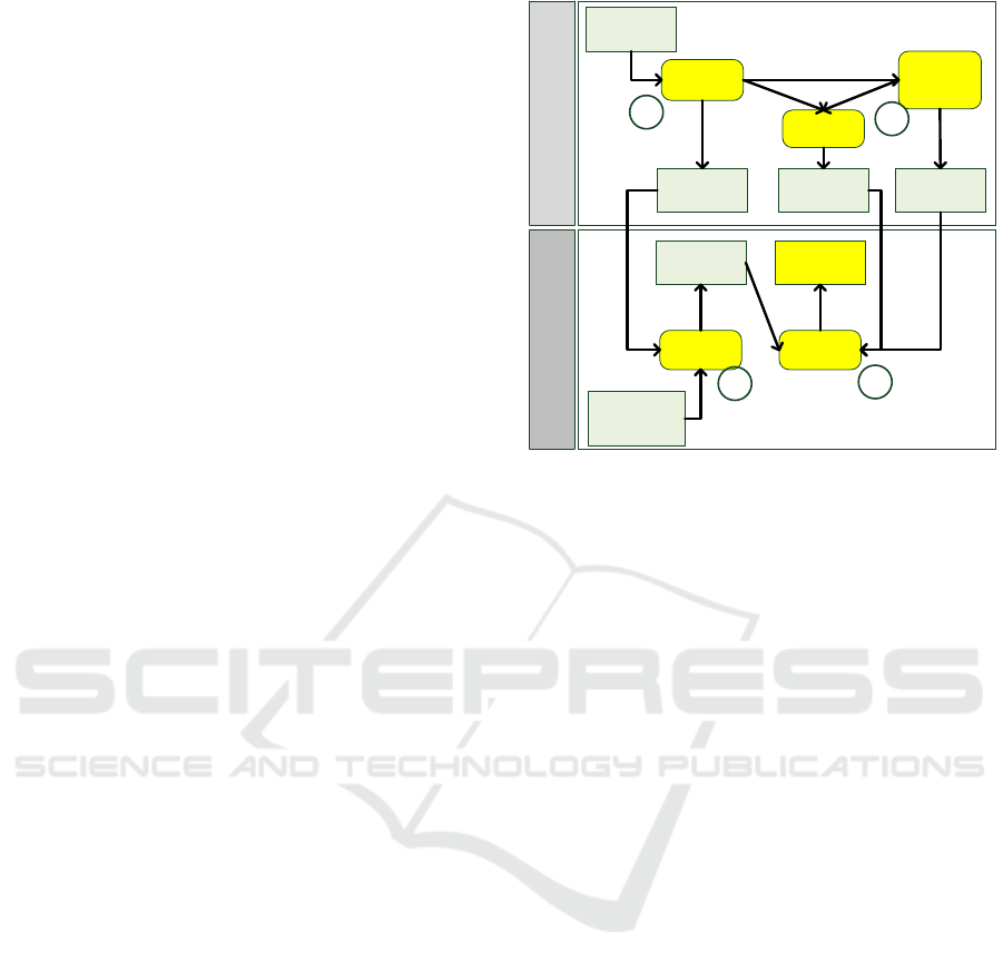
Analyze
Domain
Develop Multi-
variant
Domain Model
Establish
Mapping
Configure
Features
Configure
Product
Application Engineering
Domain Engineering
Feature Model
Multi-variant
Domain Model
Mapping
Model
Feature
Configuration
Domain
Application
Specific
Requirements
Configured
Domain Model
1
2
3
4
Figure 1: Model-driven product line engineering process
based on negative variability.
cess based on negative variability as shown in Fig-
ure 1. Typically, product line engineering distin-
guishes between domain and application engineer-
ing (Clements and Northrop, 2001; Pohl et al., 2005).
Domain engineering is dedicated to analyzing the do-
main and capturing the results in a model which de-
scribes commonalities and differences thereof. Fur-
thermore, an implementation – the so called platform
– is provided at the end of domain engineering. The
platform is then used during application engineering
to derive application specific products, i.e., instances
of the product line.
In our approach, domain and application engineer-
ing differ from each other also with respect to the re-
quired processes: Domain engineering requires a full-
fledged development process, while application engi-
neering is reduced to a simple configuration process,
which is realized in a preferably automated way. The
activities belonging to the entire engineering process
are described below:
1. Analyze Domain. A feature model describing
mandatory, optional and alternative features
within the product line captures the result of the
domain analysis. Typically, Feature-Oriented Do-
main Analysis (FODA) (Kang et al., 1990) or one
of its descendants – like FORM (Kang et al.,
1998) – is used to analyze the domain.
2. Develop Configurable Domain Model. After-
wards, a multi-variant domain model is devel-
oped, which realizes all features determined
in the previous step. A link (mapping model)
between the feature model and the domain model
MODELSWARD 2018 - 6th International Conference on Model-Driven Engineering and Software Development
328
is established, e.g., by annotating model elements
with feature expressions.
3. Configure Features. In order to build a specific
system with the reusable assets provided by the
product line, features of the feature model have
to be selected. The selected features constitute a
feature configuration, describing the characteris-
tics of the product configuration to be derived.
4. Configure Domain Model. According to the se-
lection of features made in the previous step, the
domain model is configured automatically. This
is done by selecting all domain model elements
which are not excluded by feature expressions
evaluating to false. The result of this step is an
application-specific configured domain model.
Please note that the activity Develop Multi-variant
Domain Model comprises the phases Domain Re-
quirements Engineering, Domain Design, Domain
Implementation and Domain Testing, as described in
the product line process proposed by Pohl et al. (Pohl
et al., 2005). In a model-driven software engineer-
ing process, the corresponding artefacts produced by
these subprocesses are represented as models. This
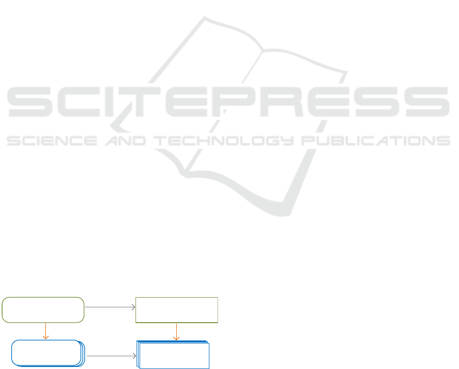
fact leads to the so called “filter/transform” dilemma:
Assuming, that a M2M-transformation exists, which
derives required artefacs from the multi-variant do-
main models, an initial approach would be to have
variability annotations only on the source model and
then call the filter operation for the source model
in application engineering followed by a subsequent
transformation to obtain the target product (and man-
ually add extensions, e.g., method bodies in appli-
cation engineering). However, this contradicts our
requirement, that application engineering should be
reduced to a pure and automatic configuration task.
Thus, the transformation of the source multi-variant
domain model must be executed in domain engi-
neering and the variability information needs to be
synchronized automatically with the derived target
model(s). Consequently, in application engineering
only an automatic filter operation to both, source and
target models, is required (c.f., Figure 2).
Source Multi-Variant
Domain Model
Target Multi-Variant
Domain Model
Source
Products
Single-variant
target models
transform
transform
filter(conf) filter(conf)
Single-variant
target models
Target
Products
Figure 2: Model-driven product line engineering process as
supported with FAMILE.
3.2 FAMILE: Tool Architecture
FAMILE (Features and Models in Lucid Evolution) is
an EMF-based MDPLE tool chain that offers capa-
bilities to capture commonalities and variabilities of
a software family using feature models and to map
features to elements of arbitrary EMF-based domain
models, which contain the realization of those fea-
tures. FAMILE has been developed itself in a model-
driven way, being based on several meta models. The
feature meta model describes the structure of feature
models and feature configurations, respectively, and
F2DMM (Feature to Domain Mapping Model) is the
meta model for mappings between features and re-
alization artefacts (elements of the multi-variant do-
main model).
Figure 3 shows the (meta) models involved in the
tool chain. A feature model (Batory, 2005) consists of
a tree of features. A non-leaf feature may be decom-
posed in two ways. In the case of an AND decom-
position, all of its child features have to be selected
when the parent is selected. In contrast, for an OR
decomposition exactly one child has to be selected.
In addition, our feature modeling tool complies with
cardinality-based feature modeling (Czarnecki et al.,
2005). EMF Validation is used to check correspond-
ing feature configurations against pre-defined consis-
tency constraints (Heidenreich, 2009).
FAMILE’s core component is an editor for map-
ping models (F2DMM), which is used to interconnect
the feature model and the Ecore-based domain model.
To this end, a mapping model consists of a tree of
three different kinds of mappings, which are created
by the tool transparently to reflect the tree structure of
the mapped domain model:
Object Mappings refer to an existing EObject from
the multi-variant domain model and reflect its
tree structure using the Composite design pattern
(Gamma et al., 1994).
Attribute Mappings refer to the string representa-
tion of a concrete value of an attribute of a mapped
object.
Cross-reference Mappings represent the applied
occurrence of an object that is already mapped by
an object mapping.
The connection between domain and feature
model is realized by feature expressions specified
with FAMILE’s Feature Expression Language (FEL).
A feature expression may be assigned to each kind
of mapping and consists of a propositional logical ex-
pression on the variables defined in the feature model.
Once a valid feature configuration is provided,
FAMILE may be used to derive the configured
Managing Variability in Models and Derived Artefacts in Model-driven Software Product Lines
329
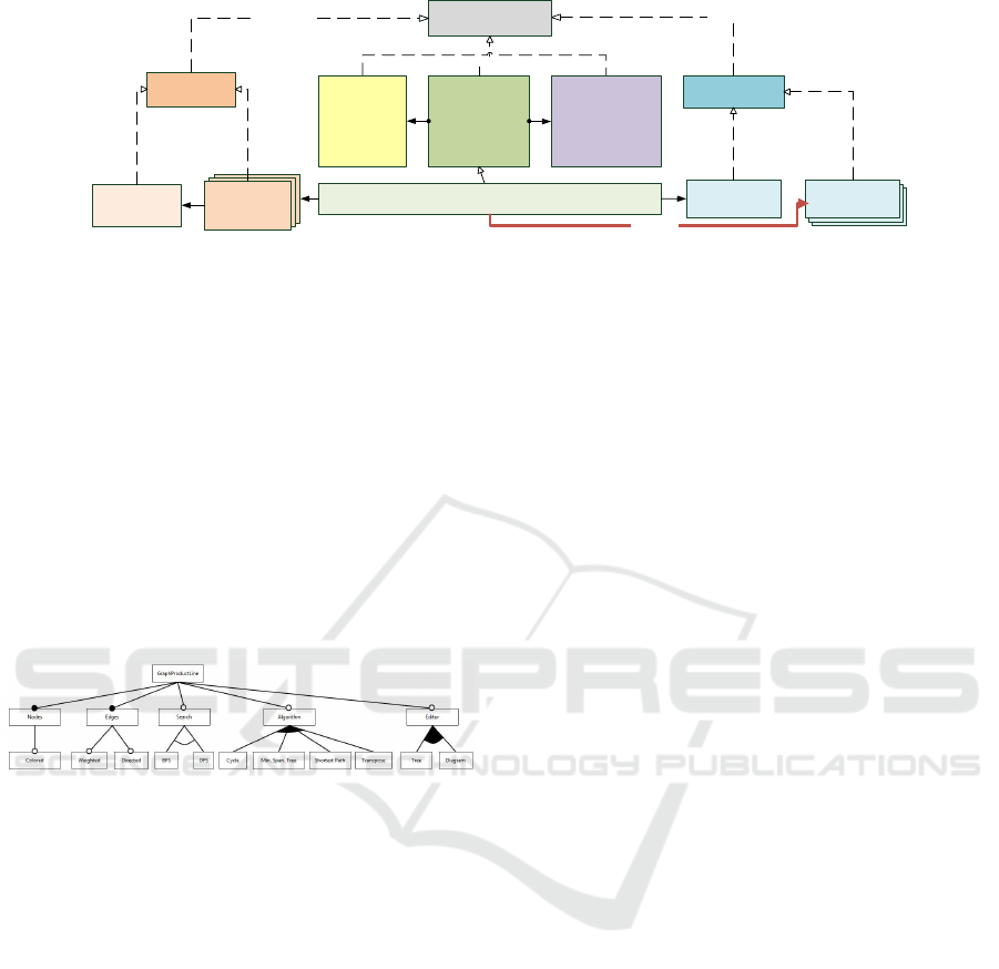
corresponds to
Ecore
Meta model
Feature
Meta model
Feature
Model
Feature
Configuration
corresponds to
Domain
Meta model
Multi-variant
Domain model
Feature to
Domain
Mapping Model
(F2DMM)
Meta model
corresponds to
Feature
Expression
Language
(FEL)
Meta model
Structural
Dependency
Identification and
Repair Language
(SDIRL)
Meta model
Feature 2 Domain Maping Model (F2DMM)
Configured
Domain model
derives
Figure 3: Architectural overview of FAMILE.
domain model by filtering all domain model ele-
ments decorated with feature expressions evaluating
to false. During product derivation, repair actions are
applied to ensure well-formedness (Buchmann and
Schw
¨
agerl, 2012). To this end, context-free consis-
tency constraints are automatically derived from the
used domain meta model. Furthermore, the SPL en-
gineer may specify context-sensitive constraints using
the textual language SDIRL (Structural Dependency
Identification and Repair Language).
4 MOTIVATING EXAMPLE
Figure 4: Feature model for the graph product line.
A prominent example in literature on software prod-
uct lines is a product line for graphs.
Figure 5 depicts the multi-variant domain model
of the graph product line. Following the model-driven
approach, an object-oriented decomposition of the
underlying data structure is applied: A Graph con-
tains Nodes and Edges. Furthermore, it may contain
a Search strategy and Algorithms operating on the
graph data structure. For performance reasons, the
data structure may be converted into an Adjacency
list, to speed up certain algorithms. As the model de-
picted in Fig. 5 is the superimposition of all variants,
the relation between nodes and edges is expressed in
multiple ways: (1) In case of undirected graphs, an
edge is used to simply connect two nodes, expressed
by the reference nodes. (2) Directed graphs, on the
other hand, demand for a distinction of the respective
start and end nodes of an edge. This fact is expressed
by two single-valued references named source and
target, respectively.
As stated above, common modeling tools typi-
cally allow for structural modeling and code gener-
ation from these models. Thus, the practical MDSE
development process demands for a manual speci-
fication of an Operation’s body by completing the
generated source code. In the example, hand-written
Java source code for all operations contained in the
class diagram shown in Figure 5 has been supplied.
A small cut-out of a method implementation for the
class Search is shown in Figure 6. In the correspond-
ing UML model (c.f. Fig. 5), the Search class defines
three Operations. Since code generation engines typ-
ically only create Java code for the method head, the
body implementation depicted in Figure 6 needs to
be supplied manually. In this case, the method im-
plementation also contains variability as the corre-
sponding references between nodes and edges are dif-
ferent depending on the presence or absence of the
feature Directed in the current feature configuration.
Please note that the level of granularity supported by
FAMILE’s variability annotations is arbitrary, ranging
from single Java fragments, over statements, blocks,
methods or even classes and packages.
As mentioned earlier, FAMILE supports the de-
velopment of software product lines based on nega-
tive variability. Thus, when deriving specific products
based on a concrete feature configuration, all frag-
ments and artefacts which do not contain selected fea-
tures have to be removed. Figure 7 depicts the situa-
tion that would occur, if only standard modeling tech-
nology without the mechanism described in this paper
would have been used.
During Domain Engineering, the platform con-
taining all variants is created. This can be done in
a model-driven way using any Ecore-based model (in
this case: Eclipse UML2) to describe the static struc-
ture of the software (contained in the Domain Model),
invoking the code generator (Step 1 in Figure 7) and
using hand-written Java code to specify the method
bodies. The hand-written code is added to the gener-
ated one and then discovered into an Ecore-compliant
AST model (contained in the Java Model, c.f., Section
5.1) in order to be able to use FAMILE for variability
management on the source code fragments (Step 2).
Please note that the FAMILE tool chain is orthogonal
MODELSWARD 2018 - 6th International Conference on Model-Driven Engineering and Software Development
330
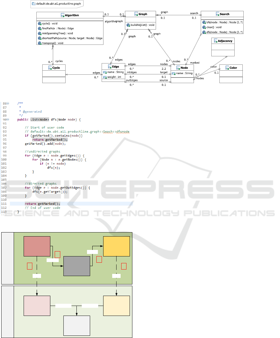
Figure 5: UML model for the graph product line.
Figure 6: Example for method bodies written in Java.
Domain
Model
Java Model
Domain
Model‘
Java Model‘
Java Code
generate
discover
Java Code‘
generate (1)generate (2)
derive derive
Application Engineering
Domain Engineering
1
2
3
3
Figure 7: The interplay between model and hand-written
code in (heterogeneous) model-driven software product
lines.
to any development tool, which allows for reusing ex-
isting tools in the model-driven software product line
process. The variability information is stored in a sep-
arate model. Consequently, when invoking the code
generation of the used modeling tool, the variability
information is not contained in the source code, and
thus, it is also missing in the discovered Java AST
model. Furthermore, annotating for example an At-
tribute in the class diagram would require to annotate
the corresponding field declaration and the respective
accessor methods in the generated source code. In or-
der to not confuse the user of the tool and to keep
the annotation effort as small as possible, it is not
a feasible solution to force the user to synchronize
the variability annotations manually. During Appli-
cation Engineering, when unused fragments are fil-
tered from the multi-variant models, the correspond-
ing target models are derived (Domain Model’ and
Java Model’ respectively), depicted as Step 3 in Fig-
ure ??. In an ideal world, i.e. both models are in sync
in terms of variability information, the user could in-
voke the automatic product derivation. However, real-
ity is different: Some code merging generators (e.g.,
the EMF code merging generator) does not remove
files. For example, an annotated class of the Ecore
model was filtered during the derivation process but it
is still present in the Java model. If the code gener-
ation for the Java model is invoked first, correspond-
ing Java code for this class is generated which is not
deleted on a subsequent run of the code generation.
The same holds for operations: The EMF code gener-
ation requires that hand-written code is marked in or-
der to preserve it during subsequent generation steps.
In case an Operation that has been extended with a
hand-written body is filtered in the Ecore model, this
mechanism prevents it from being deleted.
In the following we describe a generic mecha-
nism, which allows to automatically propagate vari-
ability annotations expressed by FAMILE’s feature
expressions to the discovered Java AST model.
Managing Variability in Models and Derived Artefacts in Model-driven Software Product Lines
331
5 PROPAGATING FEATURE
EXPRESSIONS
5.1 Representing Source Code as a
Model
As described in Section 3.2, our tool chain FAMILE
can handle any Ecore-based models. To this end, any
source code fragments that contain variability man-
aged by FAMILE need to be represented as a model.
The tool MoDisco (Bruneliere et al., 2010) offers a
possibility to represent Java source code as an Ecore-
compliant Java model. Unfortunately, the standard
MoDisco discovery mechanism works in batch mode
only, i.e., each time the source code is changed and
the discoverer is invoked, the previous Java model
is discarded and constructed from scratch. In order
to preserve variability annotations that the software
product line engineer might have added to the Java
model, an incremental mode of operation is required.
To this end, we created our own discoverer which
reuses the MoDisco Java model but works in a highly
incremental way. In subsequent runs, the existing
model is checked and only updates are propagated.
In case of named elements, the detection of modifi-
cations and deletions is quite easy, as the context of
the element can be analyzed. However, certain ele-
ments of the statement level do not have unique names
in the AST. In this case, we exploit the Eclipse Java
delta mechanism, which provides information about
added and deleted elements of the Java AST. Unfortu-
nately, this information is rather coarse grained. Thus,
we decided to also implement a delta mechanism
based on the Jaro-Winkler-distance calculation (Win-
kler, 1990). An Eclipse builder mechanism ensures,
that a FAMILE project automatically runs our Java
discoverer, once the source code has been changed.
As a result, the discovered Java model, which con-
tains variability information handled by FAMILE is
always in sync with the source code.
5.2 The MSync Language
As our tool chain FAMILE is generic and is not
specifically designed for a certain domain model, the
solution needs to be generic as well. We implemented
a mechanism, similar to the one which is used to pre-
serve the consistency of configured domain models,
as described in (Buchmann and Schw
¨
agerl, 2012). A
textual language, allowing to formalize consistency
constraints for a given domain meta model and a
propagation mechanism is used to propagate selection
states, ensuring similar states for depending model el-
ements.
In our solution, we adopted this mechanism to
work on different meta models in order to propagate
variability information from one model to another
one. Thus, variability annotations in a domain model
(e.g. in a class diagram) may be transferred to the cor-
responding generated source code artefacts, which are
then also represented as an Ecore-compliant model in-
stance as discussed in Section 5.1. Furthermore, the
solution is generic inasmuch as no knowledge about
the actual M2M transformation or the M2M tool is re-
quired. The relation between elements of source and
target models is done based on the respective input
and output models of the transformation.
To this end, we created a textual DSL called
MSync, whose syntax resembles ATL (Jouault et al.,
2008). The language allows to formulate derivation
rules, which indicate how model elements are ex-
pressed by corresponding derived artefacts.
The DSL allows to specify rules, which describe
in a declarative way, how elements of the source
model are mapped onto elements of the target model
(1:n mappings).
5.3 Synchronize Variability Information
Please note that in our example we address derivation
rules for a model-to-model (M2M) transformation be-
tween a UML model and a Java model. The Java
model is discovered from Java source code, which has
been generated by a M2T transformation applied to
the UML model. This scenario reflects the common
use case of extending source code generated from
CASE tools in a practical MDSE process.
Listing 1 depicts a cutout for the mapping of UML
class diagrams to a Java model, discovered from gen-
erated source code (created by the UML case tool
Valkyrie (Buchmann, 2012)). Please note that this
rule file only needs to be specified once for each trans-
formation tool and may be reused for any product line
created with this specific tool.
1 importMetaModel "platform:/resource
/de.ubt.ai1.ModelSync.
Interpreter/models/java.ecore"
2 importMetaModel "platform:/resource
/de.ubt.ai1.ModelSync.
Interpreter/models/UML.ecore"
3
4 define sourcemodel: uml;
5 define targetmodel:java ;
6
7 rule Package2Package {
8 source umlP : Package
9 target javaP : Package {
10 javaP.name = umlP.name;
11 java.P.package.name = umlP.
nestingPackage.name;
MODELSWARD 2018 - 6th International Conference on Model-Driven Engineering and Software Development
332

12 }
13 }
14
15 rule Class2Class {
16 source umlC : Class
17 target javaC : ClassDeclaration {
18 javaC.name = umlC.name ;
19 javaC.package.name = umlC.
package.name;
20 }
21 }
22
23 ...
24
25 rule Property2Field {
26 source umlProp : Property (
umlProp.upper == 1)
27 target javaField :
FieldDeclaration {
28 javaField.fragments.name =
umlProp.name;
29 javaField.type.type = umlProp.
type;
30 }
31 target javaSetter :
MethodDeclaration {
32 javaSetter.name = "set" +
umlProp.name:toUpperFirst()
;
33 }
34 target javaGetter :
MethodDeclaration {
35 javaGetter.returnType.type =
umlProp.type;
36 javaGetter.name = "get" +
umlProp.name:toUpperFirst()
;
37 }
38 }
39
40 rule Property2FieldMany {
41 source umlProp : Property (
umlProp.upper <> 1)
42 target javaField :
FieldDeclaration {
43 javaField.fragments.name =
umlProp.name;
44 javaField.type.type = umlProp.
type;
45 }
46 target javaSetter :
MethodDeclaration {
47 javaSetter.name = "addTo" +
umlProp.name:toUpperFirst()
;
48 }
49 target javaGetter :
MethodDeclaration {
50 javaGetter.name = "get" +
umlProp.name:toUpperFirst()
;
51 javaGetter.returnType.type =
umlProp.type;
52 }
53 target javaSizeOf :
MethodDeclaration {
54 javaSizeOf.name = "sizeOf" +
umlProp.name:toUpperFirst()
;
55 }
56 }
57
58 ...
Listing 1: Cutout of MSync file for the UML to Java
code generation.
A relation between source and target elements is
specified in a rule. Within a rule, a source element
is related to one or many target elements. Lines 7-13
in Listing 1 depict the relation between UML pack-
ages and Java packages. Within the target block, at-
tribute constraints are specified in order find matching
pairs. In this case, the names of the packages need to
be equal as well as the names of the corresponding
parent packages. Similar rules are used for Classes
(c.f., Lines 15-21), Interfaces, and Enumerations
(not shown due to space restrictions). The rule that re-
lates UML properties and corresponding Java source
code fragments is shown in line 25: A single-valued
UML property is mapped to a corresponding Java
FieldDeclaration and two accessor MethodDecla-
rations. The rule for multi-valued properties is shown
in line 40.
The rules specified in the MSync file are used by
an interpreter, which requires also source and target
model instances as an input. Based on the supplied
source and target models, the corresponding F2DMM
models are used to automatically propagate feature
expressions for matching pairs of source and target
model elements.
In the following Section, we demonstrate the use
of the tool extension to the motivating example from
Section 4.
6 EXAMPLE REVISITED
We now apply the approach presented in the previous
section to the example given in Section 4. After the
variabilities and commonalities have been captured in
a feature model, we start to create a UML class di-
agram reflecting the static structure of our product
line, as shown in Figure 5. We add variability an-
notations to the corresponding model fragments with
the help of FAMILE. After that, Java code is gener-
ated using the Valkyrie code generator. The supplied
Eclipse builder ensures that now the Java discovery
Managing Variability in Models and Derived Artefacts in Model-driven Software Product Lines
333
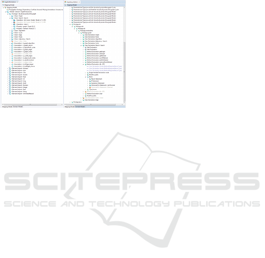
Figure 8: Mapping models for an example configuration.
mechanism is started in order to create a Java model
which reflects the generated code. After that, a cor-
responding F2DMM mapping model is automatically
created for the new Java model, and the variability
annotations specified for the class diagram are syn-
chronized. After this automatic process, we begin to
supply the method bodies, e.g., the one shown in Fig-
ure 6. Please note that this method body also contains
variability, so the corresponding statements also need
to be annotated accordingly. After incorporating the
changes, the build mechanism runs the incremental
discovery mechanism again (triggered by a save op-
eration) and our changes are propagated into the Java
model. The newly added statements are now anno-
tated with the respective feature expressions, while
running the discovery mechanism retained the ones
which were already present from the previous step.
Please note that our mechanism supports an iterative
work flow, i.e., the class model may be changed and
code may be regenerated. After finishing the domain
engineering step, products may be derived in appli-
cation engineering. Figure 8 depicts cutouts of the
F2DMM models for the class diagram (left-hand side
of the figure) and the Java code (right-hand side of the
figure) for a sample configuration. This configuration
allows to generate a base graph with unweighted and
undirected edges and a depth first search. When de-
riving the product, all heterogeneous artefacts contain
the required elements to build a product complying to
the feature selection specified in the feature configu-
rations. Model elements and derived artefacts are in
sync and the corresponding code generation engine of
the Java model may be invoked (according to Figure
2).
7 EVALUATION
We successfully applied our approach to several prod-
uct lines, which have been implemented by different
tools. Besides the graph product line based on UML,
we also created a graph product line based on Ecore
class diagrams and the standard EMF code genera-
tion. Only a slightly modified MSync file (reflecting
the code style of the EMF code generation) was re-
quired in this case. Furthermore, the approach was
also used in a bigger case study dedicated to the also
well-known literature example in the context of home
automation systems (Pohl et al., 2005). With the
help of our approach, the manual annotation effort
has been decreased significantly. Furthermore, it is
ensured that annotations of domain model elements
and the corresponding derived fragments are always
in sync.
Our approach allows for a generic propagation
of variability annotations in a model-driven software
product line process. As the typical MDSE process
involves model transformations, it is crucial to syn-
chronize variability information contained in domain
models to derived artefacts. As the tool FAMILE is
orthogonal to the used MDSE tools, the variability in-
formation is stored in a separate mapping model. Fur-
thermore, FAMILE only operates on the model level,
and thus the source code which is the result of the final
transformation step in MDSE needs to be represented
as a model, too. Our declarative language MSync al-
lows to specify rules relating model elements and de-
rived artefacts, e.g., source code fragments. An in-
terpreter is used to propagate variability annotations
from domain model elements to the corresponding
target model elements (e.g., elements of the discov-
ered Java model in our example).
8 CONCLUSION
In this paper, we presented an innovative approach
for keeping variability annotations of models and de-
rived artefacts consistent in model-driven software
product lines. This is achieved by rules specified
in a declarative textual DSL, which describes rela-
tions between source and target model elements. We
showed the feasibility of our approach with an ex-
ample, where the DSL is used to specify dependen-
cies between Ecore model elements and correspond-
ing generated Java source fragments. The information
is then used to propagate variability annotations de-
clared in the Ecore model to the corresponding Java
model which is obtained from the Java source code.
Our approach ensures, that variability annotations are
MODELSWARD 2018 - 6th International Conference on Model-Driven Engineering and Software Development
334

consistent over all models and their derived fragments
during domain engineering, and thus, application en-
gineering (i.e., the derivation of products from the
product line) is a purely automated process.
Furthermore, we explained in detail how this ap-
proach provides a significant improvement in model-
driven software product line engineering (MDPLE):
Since we use a generic tool chain for MDPLE, con-
ceptual links between different models, e.g., an Ecore
model and a corresponding Java model containing
body implementations cannot be hard coded in the
tool. In order to provide consistency between these
types of models, the information stored in both of
them has to be integrated using the approach dis-
cussed in this paper.
REFERENCES
Batory, D. S. (2005). Feature models, grammars, and propo-
sitional formulas. In Obbink, J. H. and Pohl, K., ed-
itors, Proceedings of the 9th International Software
Product Line Conference (SPLC’05), volume 3714
of Lecture Notes in Computer Science, pages 7–20,
Rennes, France. Springer Verlag.
Bruneliere, H., Cabot, J., Jouault, F., and Madiot, F. (2010).
MoDisco: a generic and extensible framework for
model driven reverse engineering. In Proceedings
of the IEEE/ACM International Conference on Auto-
mated software engineering (ASE 2010), pages 173–
174, Antwerp, Belgium.
Buchmann, T. (2012). Valkyrie: A UML-Based Model-
Driven Environment for Model-Driven Software En-
gineering. In Proceedings of the 7th International
Conference on Software Paradigm Trends (ICSOFT
2012), pages 147–157, Rome, Italy. SciTePress.
Buchmann, T. and Schw
¨
agerl, F. (2012). Ensuring well-
formedness of configured domain models in model-
driven product lines based on negative variability.
In Proceedings of the 4th International Workshop
on Feature-Oriented Software Development, FOSD
2012, pages 37–44, New York, NY, USA. ACM.
Buchmann, T. and Schw
¨
agerl, F. (2015). On A-posteriori
Integration of Ecore Models and Hand-written Java
Code. In Pascal Lorenz, M. v. S. and Cardoso, J.,
editors, Proceedings of the 10th International Con-
ference on Software Paradigm Trends, pages 95–102.
SciTePress.
Clements, P. and Northrop, L. (2001). Software Prod-
uct Lines: Practices and Patterns. Addison-Wesley,
Boston, MA.
Czarnecki, K., Helsen, S., and Eisenecker, U. W. (2005).
Formalizing cardinality-based feature models and
their specialization. Software Process: Improvement
and Practice, 10(1):7–29.
Famelis, M., L
´
ucio, L., Selim, G., Di Sandro, A., Salay, R.,
Chechik, M., Cordy, J. R., Dingel, J., Vangheluwe, H.,
and Ramesh, S. (2015). Migrating automotive product
lines: a case study. In International Conference on
Theory and Practice of Model Transformations, pages
82–97. Springer.
Frankel, D. S. (2003). Model Driven Architecture: Apply-
ing MDA to Enterprise Computing. Wiley Publishing,
Indianapolis, IN.
Gamma, E., Helm, R., Johnson, R., and Vlissides, J.
(1994). Design Patterns - Elements of Reusable
Object-Oriented Software. Addison-Wesley, Upper
Saddle River, NJ.
Greiner, S., Schw
¨
agerl, F., and Westfechtel, B. (2017). Re-
alizing multi-variant model transformations on top of
reused ATL specifications. In Pires, L. F., Hammoudi,
S., and Selic, B., editors, Proceedings of the 5th In-
ternational Conference on Model-Driven Engineering
and Software Development (MODELSWARD 2017),
pages 362–373, Porto, Portugal. SCITEPRESS Sci-
ence and Technology Publications, Portugal.
Heidenreich, F. (2009). Towards systematic ensuring well-
formedness of software product lines. In Proceedings
of the 1st Workshop on Feature-Oriented Software De-
velopment, pages 69–74, Denver, CO, USA. ACM.
Jouault, F., Allilaire, F., B
´
ezivin, J., and Kurtev, I. (2008).
ATL: A model transformation tool. Science of Com-
puter Programming, 72:31–39. Special Issue on Ex-
perimental Software and Toolkits (EST).
Kang, K. C., Cohen, S. G., Hess, J. A., Novak, W. E.,
and Peterson, A. S. (1990). Feature-oriented do-
main analysis (FODA) feasibility study. Technical Re-
port CMU/SEI-90-TR-21, Carnegie-Mellon Univer-
sity, Software Engineering Institute.
Kang, K. C., Kim, S., Lee, J., Kim, K., Kim, G. J., and Shin,
E. (1998). Form: A feature-oriented reuse method
with domain-specific reference architectures. Annals
of Software Engineering, 5:143–168.
OMG (2015). Meta Object Facility (MOF) Version 2.5.
OMG, Needham, MA, formal/2015-06-05 edition.
Pohl, K., B
¨
ockle, G., and van der Linden, F. (2005). Soft-
ware Product Line Engineering: Foundations, Prin-
ciples and Techniques. Springer-Verlag, Berlin, Ger-
many.
Salay, R., Famelis, M., Rubin, J., Sandro, A. D., and
Chechik, M. (2014). Lifting model transformations
to product lines. In 36th International Conference on
Software Engineering, ICSE ’14, Hyderabad, India -
May 31 - June 07, 2014, pages 117–128.
Steinberg, D., Budinsky, F., Paternostro, M., and Merks,
E. (2009). EMF Eclipse Modeling Framework. The
Eclipse Series. Addison-Wesley, Boston, MA, 2nd
edition.
V
¨
olter, M., Stahl, T., Bettin, J., Haase, A., and Helsen, S.
(2006). Model-Driven Software Development: Tech-
nology, Engineering, Management. John Wiley &
Sons.
Winkler, W. E. (1990). String comparator metrics and en-
hanced decision rules in the fellegi-sunter model of
record linkage.
Managing Variability in Models and Derived Artefacts in Model-driven Software Product Lines
335
