
A Topological-Geometrical Pipeline for 3D Cracking-like Phenomena
Jérémy Riffet
1
, Nicolas Castagne
1
, Emmanuelle Darles
2
and Annie Luciani
3
1
Univ. Grenoble Alpes, Grenoble INP, Institute of Engineering, ICA, 38000 Grenoble, France
2
Univ. Poitiers, CNRS, XLIM, UMR 7252, F-86000 Poitiers, France
3
ACROE, Grenoble, France
Keywords: Computer Animation and Simulation, Fractures, Splits, Cracks, Tears, Physics-based Models, Geometry-free
Approaches, Masses-interaction Networks, Motion Coating, Adjacency Graphs, Topological Modelling.
Abstract: Animation of one-to-many phenomena (fractures, tears, breaks, cracks…) is challenging. This article builds
over recent works that proposed a 3-stages modelling and simulation pipeline, made of a cascade of models:
geometry-free physical model → explicit modelling of the evolving topology → geometrical model. On the
Physics’ side, in the framework of masses-interactions network modelling, the article extends the recent
Splitting-MAT method, where the physical splits occur onto the material points, toward 3 dimensional volume
models. Downstream, it introduces a topo-geometrical pipeline adapted to this upstream split-on-the-masses
property. Experiments, and analysis of the complexity of the topo-geometrical part, show that, while offering
constructible and manageable means, separating Physical, Topological and Geometrical aspects in the 3-
stages pipeline enables a rich variety of one-to-many dynamics, with good efficiency.
1 INTRODUCTION
Fracture, tearing, breaking, cracking, or more
generally one-to-many visual dynamics featuring
topological transformations are attractive, but their
modelling and simulation are challenging. Research
has recently worked on two categories of approaches.
The first approach focuses on extending
“geometry-based” physical methods, such as Finite
Elements, Mass-Spring Meshes or Diffuse Elements
methods, toward fracturing, tearing, breaking, etc. In
such cases, the physical algorithms are embedded into
a geometrical mesh. When a topological
transformation occurs, both the geometrical and
physical models need to be co-transformed with one
another. Managing globally such geometrico-
physical remeshing process is difficult. (Muguercia et
al., 2014) and (Frerichs et al., 2015) offer surveys of
recently proposed solutions and models. In parallel
with the present work, one can also note that it has
recently been proposed to root on an explicit
representation of the topological aspects, with the aim
to manage with more control and systematism the
physico-geometrical remeshing issues (Carter et al.,
2000; Meseure et al., 2010; Fléchon et al., 2013;
Paulus et al., 2015).
In the second category of approaches, to which
this article relates, modelling and computation of the
splittable dynamics root on “geometry-free” (or
“mesh-free”, or “morphology-free”) physics-based
methods, such as: masses-interactions networks
modelling (Jund et al., 2012; Luciani and Godard,
1997), meshless techniques (Zhuang et al., 2012;
Steinemann et al., 2009; Pauly et al., 2005), smoothed
particles hydro-dynamics (Chen et al., 2013), frame-
based simulation (Manteaux et al., 2015), and others.
In these cases, the physical model is not tied to a
pre-existing geometrical mesh, and does not express
matter contiguity. This eases the modelling and
computing of the physical state changes: the physical
model can be thought of, computed, without the
burden of geometrical aspects.
Anyhow, when working with Geometry-free
physics-based approaches, the dynamics is most often
generated as a set of moving points. Consequently, a
geometrical model must be set up to visualize such
punctual movements. In the case of one-to-many
phenomena, the physical state changes must also
control downstream topological transformations
within the geometrical model.
To address this issue, (Zhuang et al., 2012) build
over the principles of level sets. (Pauly et al., 2005)
propose employing small elliptical surfaces called
Riffet, J., Castagne, N., Darles, E. and Luciani, A.
A Topological-Geometrical Pipeline for 3D Cracking-like Phenomena.
DOI: 10.5220/0006552702070214
In Proceedings of the 13th International Joint Conference on Computer Vision, Imaging and Computer Graphics Theory and Applications (VISIGRAPP 2018) - Volume 1: GRAPP, pages
207-214
ISBN: 978-989-758-287-5
Copyright © 2018 by SCITEPRESS – Science and Technology Publications, Lda. All rights reserved
207
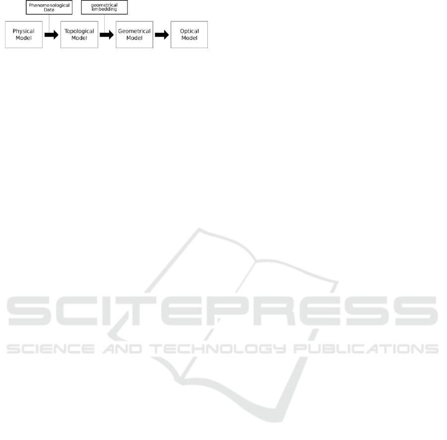
Figure 1: A cascading pipeline for the modelling and
simulation of one-to-many phenomena.
surfels. (Steinemann et al., 2009) and (Chen et al.,
2013) employ an adjacency graph set up over the
moving particles.
Another recent proposal consists in introducing a
model explicitly dedicated to the topological aspects.
Besides first experiments in (Darles et al., 2011),
(Jund et al., 2012) and (luciani et al, 2014) position a
global modelling and simulation pipeline, made of a
cascade of submodels, from upstream to downstream
(Figure 1): a physics-based model → a topological
model → a geometrical model. Employing a central
topological model helps managing efficiently,
systematically and formally the topological
transformation, under control of the physics-based
punctual movements. Also, segmenting the complete
model in layers of submodels makes it possible to tie
each of the models to a clearly delimited part of the
final visual phenomena: splittable dynamics thanks to
the physical model; management and transformations
of the relations thanks to the topological model;
geometry thanks to the geometrical model.
Recently, in the context of Geometry-free
physics-based approaches, (Kalantari et al., 2014)
extended masses-interactions networks modelling, by
introducing the Splitting MAT system. This system
allows the splits to occur directly on the material
points, though without any computational overhead.
However, Splitting MAT have not yet been employed
within the global Physics → Topology → Geometry
pipeline.
This article extends the original pipeline proposed
in (Jund et al., 2012) and related articles to the cases
where Splitting-MAT (Kalantari et al., 2014) are
employed on the upstream Physics’ side. Our
contributions are:
1/ On the physics-based side, we extend the
Splitting-MAT method to the case of splittable three-
dimensional volume models.
2/ Downstream, we introduce a topological-
geometrical coating pipeline adapted to the splitting-
MAT principles in 3D. We explain how the upstream
split-on-the-masses property eases setting up the
topo-geometrical process downstream.
3/ We present various experiments on fractures,
breaks and tears phenomena. We show that the
pipeline allows modelling and simulating a range of
fracturing/cracking/tearing effects with good
efficiency, possibly at interactive frame-rate.
2 THE TOPO-GEOMETRICAL
PIPELINE
This section presents the proposed
physical→topological→geometrical pipeline built
over the Splitting MAT method. Section 2.1
summarizes the principles of the Splitting MAT
physics-based system, and discusses the upstream
physical model with Splitting MAT. Section 2.2
covers the data exported from the physics toward the
topological, then geometrical stages. Section 2.3
provides details on the G-Map topological system we
employ. Section 2.3 covers the topo-geometrical
pipeline downstream: as originally proposed in (Jund
et al. 2012), we present successively the
Construction, Association, Modification and
Affectation steps.
For more clarity, throughout this section,
explanations are first based on an exemplary 2D
model, which is globally summarized on Figure 3. In
each paragraph, we briefly explain how the pipeline
can be evolved to 3D volume models. The
experimental models presented in section 3 are all 3D
volume models.
2.1 Physical Model with Splitting MAT
The Splitting-MAT methodology extends the
possibilities of masses-interactions networks
modelling in regards to one-to-many phenomena
(fractures, breaks, tears…), by enabling the splits to
occur directly onto the MATerial points – the masses
of the network. The method has a fully constant
algorithmic complexity, and guarantees by
construction the stability of the physics, no matter
how the model evolves (break, tear, split…) during
simulation. (Kalantari et al., 2014) provides details on
the system and its stable computing cost.
Modelling with splitting–MAT starts by defining
the smallest possible physical entities, corresponding
to the fully-split state, by interconnecting some
masses with physical interactions. Then, masses of
various entities are united into Mass-unions. A Mass-
union is created by tying its masses one to another
with Duplets. As long as a duplet remains active, the
2 tied masses remain in the same Mass-union, and
will keep the same exact behaviour: same position,
same speed. Each Duplet is associated with a Sensor
which, when triggered, inactivates the Duplet.
GRAPP 2018 - International Conference on Computer Graphics Theory and Applications
208
Depending on the emerging phenomena, duplets may
be progressively inactivated, leading to Mass-unions’
splits. Hence, masses may progressively gain their
autonomy, possibly down to the fully-split state.
When working with 2D models, each elementary
physical entity could be made of 3 or 4 masses. Figure
3 (a, b, c, left side) explain how the physical model
could be built while modelling, and split during
simulation, in the case of a very simple exemplary 2D
model made of only 4 elementary physical entities, 13
masses, and 5 Mass-unions.
In this work, on the physics-based side, we extend
the Splitting-MAT method to 3D volume models –
where only surfacic models where presented in
(Kalantari et al, 2014). To work in 3D, each
elementary physical entity can be made of 8 masses,
and various interactions, that form a hexahedral
physical entity (Figure 4a). Then, up to 8 masses
taken from 8 different smallest physical entities are
tied into initial Mass Unions, by using a minimum of
7 duplets (Figure 4b). During simulation, the splitting
process is then exactly the same as in 2D, even though
each mass has a 3D position and velocity.
2.2 Data Passed to the
Topo-geometric Stage
In our proposed pipeline, only phenomenological data
generated from the physics-based model are passed to
the topo-geometrical level. Two categories are
considered in this work.
The first consists in the punctual movements of
each of the masses of the physical model, sampled at
the physics’ simulation frequency, no matter they are
gathered in Mass-unions or not. Each of these
punctual movements is called an evolution function
(Luciani et al., 2014).
The second consists in the state of the Mass-
unions. This data stream is new as compared to
(Luciani et al., 2014), which did not employ Splitting
MAT. The Mass-unions’ state data stream is event-
based: whenever a Mass-union splits in the physics,
the indexes of the masses forming the newly created
Mass-unions are passed to the downstream model
along with the date of the event.
2.3 Adjacency Graphs Fundamentals
In order to handle easily and formally topological
constructs and modifications in large volume sets, we
employ a structure that stores cells adjacencies. There
exist many graph models in the literature, such as for
example half-edges graphs.
Figure 2: Two darts sewed by α
0
link form an edge (black
lines). Several edges sewed by α
1
links (red curves lines)
form a face. Several faces sewed by α
2
links (green large
dotted lines) form a volume. Several volumes sewed by α
3
links (blue thin dotted lines) form one connected
component.
In this work, we employ the generalized map
formalism (Lienhart, 1994). Each cell in dimension N
(N>0) is created by sewing different N-1-D cells to
obtain a N-D cell. Hence, a 1D cell (topological
vertex) is created by sewing 0D elementary cells
called “darts”. Sew operations are mathematically
defined as bijective functions
i
(with i the dimension
of the sew operation) called involutions. The N-D
topological cells are the nodes of the adjacency graph,
and the involutions represent its edges. Topological
cells, such as topological vertices, edges or faces, then
correspond to a set of darts that are sewed with each
other’s with chosen involutions, called orbit (Figure
2).
Interestingly, the system enables finding any
adjacency relations quickly and automatically, by
using simple graph scanning. Additionally, it builds
on generic principles to guarantee consistency and
coherency of the topology during construction, and
whenever performing any topological modification.
2.4 Topo-geometrical Pipeline
Downstream Physics, to finally obtain a visible
evolving geometry, the proposed topo-geometrical
pipeline roots on 4 steps: in first, during the modelling
stage, construction and association steps. Secondly,
during the simulation stage, modification and
affectation steps.
2.4.1 Construction
The first step, called Construction, consists in
building an initial topology, which will be the core of
the entire topo-geometrical pipeline and will be
evolved during simulation.
As compared to (Kalantari et al, 2014), employing
Splitting MAT in the Physics makes it possible to
build a simple base topology. This is a important
advantage as compared to previous works on the 3
stages pipeline that did not employ Splitting-MATs.
A Topological-Geometrical Pipeline for 3D Cracking-like Phenomena
209

This base topology can be obtained simply by
employing a building process similar to the physical
model’s building process.
Figure 3a shows how the base initial topology
obtained in the case of simple use-case 2D model. It
is made 4 topological polygonal faces, sewed with
each other to form a single large polygonal surface.
Hence, each 2D elementary physical entity
corresponds to a polygonal face.
When working with 3D volume models, the
building of the base initial topology follows the same
process. Though, instead of leading to polygonal
faces, it results in tetrahedral topological volumes,
sewed in α
3
. Each of these volumes corresponds to an
elementary entity in the physical model. Noticeably,
besides the base topology discussed in this article, it
would be equally possible to experiment with other
topologies (e.g. refined).
2.4.2 Association
Association consists in bijectively associating each
evolution function to one or several elements in the
topological structure (darts, orbits, etc.).
Employing Splitting-MATs on the physical level
enables a cunning association strategy, as compared
to previous works without Splitting MATs. This
association is achieved by traversing the topological
structure in the same order the physical model was
built. During this scan, the evolutions functions are
associated one after another to a selected orbit in the
topological model.
In 2D, the proposed association roots on the
notion of face’s corner, topologically defined as the
set of darts in the orbit< α
1
> of a chosen dart. Figure
3b illustrate the resulting Association in the case of
the simple 2D exemplary model. Each evolution
function (each moving material point) is associated
with a single face’s corner orbit in the topological
structure. For example, the topological vertex in the
centre of the topological model is made of 4 face’s
corners, each one gathering 2 darts. These 4 face’s
corners are associated to the 4 corresponding
evolution functions output from the physics model. It
should be reminded that, since masses will keep the
same exact position as long as they remain in the same
Mass-Union, the corresponding face’s corners will be
associated downstream to this unique position, until a
split occurs in the Physics.
The proposed association strategy extends rather
simply to 3D, by considering the notion of volume’s
corner, instead of face’s corner. A volume’s corner is
topologically defined as the set of darts in the orbit<
α
1
,
α
2
> of a chosen dart. Hence, as we use tetrahedral
volumes in the Experiment section, we simply have
to associate each evolution function with a single
volume’s corner (instead of a face’s corner).
In G-Map data structure, storing associations in
the topology is achieved by storing the evolution
function’s index in the orbit. Constant time access is
achieved from any dart of the orbit to the value (i.e
position) of the associated evolution function.
2.4.3 Modification
During simulation, the Modification step consists in
progressively transforming the topological model, to
implement topologically fractures and splits under
control of the Physics. As compared to (Luciani et al.,
2014), employing splitting MATs upstream enables a
more direct control of the topological
transformations, thanks to the events received
whenever a Mass-union splits in the Physics. In the
case of our 2D simple exemplary model, the
modification process would simply consist in
unsewing from each other’s the face’s corners which
ids are not any more in the same Mass-union (figure
3c). In this process, the GMap’s implementation
automatically maintains the consistency of the
topology, so avoid non-manifold topology. As a
consequence, in 2D, unsewing two face’s corners
ultimately, and automatically, results in separating
topological edges.
When working with 3D volume models, a Mass-
union splits results in separating the two
corresponding volume’s corners (instead of face’s
corners). Even in the third dimension, the GMap’s
implementation ensures the consistency of the
topology. Consequently, unsewing the 2 volume’s
corners automatically unsews all the α
3
links between
the adjacent darts of these corners. This results in
separating faces of two adjacent topological volumes.
We can retrieve in constant time the involutions to
unsew in response to a split event received from the
physical model by the simple correspondences
between the upstream physical masses and the
topological face’s corners in 2D (or volume’s corners
in 3D) of the base topology.
2.4.4 Affectation and Geometrical Model
During simulation, Affectation, consists in setting up
on each rendering step a visible geometry, by
embedding geometrically the topological map. With
this step, the one-to-many phenomena are finally
shaped to the eye.
GRAPP 2018 - International Conference on Computer Graphics Theory and Applications
210
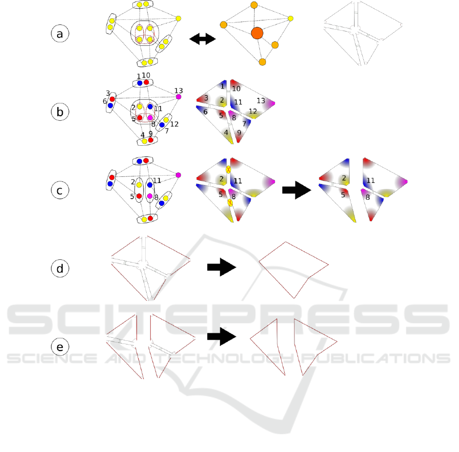
Figure 3. Simple exemplary 2D model illustrating the topo-geometrical Pipeline’s Steps. (a) Construction process. Left
figure: elementary physical entities, made of masses (yellow circles) linked by interactions (dot lines), and Mass-Unions. In
the centre of the model, 3 duplets (red dot ellipses) initially gather 4 masses (yellow circles) taken from 4 different elementary
physical entities into a single Mass-union (black ellipses). As long as these 3 duplets remain active, these 4 masses will share
the same exact positions while computing. Central figure: while Mass-unions remain unsplit, all the masses gathered in each
Mass-union behave as a single mass (orange circle). Right figure: the construction of the base topological structure inspired
by the physics network. (b) Association. Association is based on the order of mass’s placements (numbers) in the physics
model. (c) Modification. In case the duplet between the mass 5 and 8 is inactivated by its Sensor, then the Mass-union splits
into two Mass-unions: some masses previously tied are now separated. This information are used in the topological model to
unsew in α
2
the two associated faces’ corners (face’s corner 2 with 11, and face’s corner 5 with 8). (d) and (e) Affectation
step. Two embedded geometry obtained from the topological structure in the course of the simulation. The first is the
geometry of the topological model before the split, and the second is the geometry of the topologic model after the split. Only
the edges that are free in α
2
(red large lines) are rendered in the geometric model.
The position given to each geometrical vertex can
be the current value of the evolution function
associated to any of the sewed face’s corner forming
the topological vertex.
To exemplify, in the case of our 2D simple model,
in figure 3d before the split and 4e after the split, we
choose the following geometrical embedding: each
topological vertex becomes a geometrical vertex,
each unsewed topological edge (without α
2
involution, in red) becomes a geometrical edge, etc.
Hence, topological faces sewed with each other’s are
rendered as a single connected geometrical face.
When working with 3D volume models, the
process is similar. We just have to take into account
the third dimension’s topological elements: the
topological volumes. When several topological
volumes are sewed, only the unsewed faces are
rendered, so as to form a single large connected
A Topological-Geometrical Pipeline for 3D Cracking-like Phenomena
211
(a)
(b)
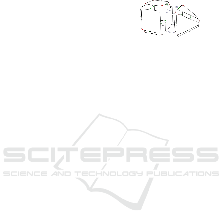
Figure 4: (a) Elementary physical tetrahedral entities with,
in blue, constraint viscoelastic interactions. (b) The set of 7
duplets, that initially gathers 8 masses taken from 8
different elementary entities into a single Mass-union. The
experimental model gathers 70x70x10 elementary physical
entities.
component. This means that several sewed
topological volumes in α
3
are rendered as a single
geometrical volume. This is made very easy thanks to
the topological model: the faces of such connected
components are simply those which α
3
involutions are
free. More complex geometrical embedding are
possible, for example, one could also choose to
embed another, possibly more complex, geometry,
such as for example: adding geometrical vertices on
the centre of each geometrical face; creating
geometrical vertices in the centre of each topological
volume; etc.
3 EXPERIMENTS AND
COMPLEXITY
For the following experiments, the Physics network
upstream is made of 70x70x10 hexahedral basic
physical entities. Each entity, corresponding to the
fully-split state, is made of 8 masses, and 16
interactions, forming a hexahedral physical entity
(Figure 4a). Then, these entities are tied to each
other’s with Duplets (Figure 4b), so as to form a large
3D physics-based splittable block. To trigger duplet’s
inactivation, we employ distance Sensors mounted
between two masses chosen in adjacent entities
outside the Mass-union. In this article, from an
experiment to another, only the physical parameters
values, and the initial state, are modified.
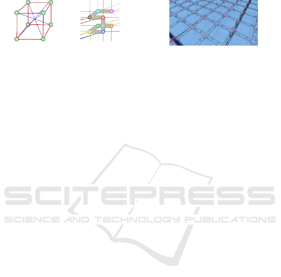
On the topological side, the base topological
model is made of 70x70x10 topological cubic
volumes that are sewed with each other’s to form a
single large parallelepiped block (Figure 5).
The two animations shown on Figure 6a and
Figure 6b were both achieved with the same exact
physical, topological and geometrical models. The
physical model stands for a slightly deformable
matter, in which Sensors’ thresholds are chosen non-
homogeneous, so as to spread various cracking lines
Figure 5: The 3D volume topological model is inspired
from the building process employed in the physics’ model:
70x70x10 topological cubic volumes are sewed to each
other’s.
in the matter. In between the two animations, only the
initial state of the physical model differs. Depending
on this initial state, cracks emerge and propagate at
various places in the simulation.
The example shown on Figure 7 illustrates
possibility of thoroughly different effects with the
pipeline. In the physical model, the parameters are set
to achieve a very deformable matter behaviour – like
a thin sheet or soft body. Then, the Sensors’
thresholds controlling Duplets inactivation are
chosen inhomogeneous over the model: the distance
thresholds are made smaller along a vertical line close
to the centre of the model. Hence, we favour a chosen
tear propagation line in the model.
The videos associated with this paper
(http://147.171.151.195:8080/fbsharing/LTWswZVk)
provide other examples illustrating further variability
in the obtainable behaviours and renderings
In all these experiments, the physical model is run
at 1050Hz: employing Splitting MAT leads to a fully
stable complexity, no matter the occurring splits. The
topo-geometrical part of the pipeline is run at 50 Hz,
and we achieved interactive framerate for all our
experiments on a standard PC.
The algorithmic complexity of the Modification
step starts by analysing the received Splitting-Mat
events. For each newly created sub-Mass-union, a
local scan of orbit<α1 , α2> is performed to determine
which volume’s corners should be unsewed from
each other’s. The complexity is O(n*m*(n+2k)), with
n the number of masses in the new Mass-union, m the
number of faces incident on the volume’s corner, and
k the number of darts in each visited face. The number
of split events to process on each step is the number
of splits that occurred in the physics since the last
execution of the topo-geometrical pipeline. Hence, in
case many Mass-unions have split in the physics, the
duration of the topological Modification step might
be penalized. However, separating the physics from
the geometry implies that this might only impact the
stability of the visual framerate, but not at all the
consistency of the physical simulation. As for it, the
memory complexity of the topological model is
GRAPP 2018 - International Conference on Computer Graphics Theory and Applications
212
(a)
(b)
Figure 6: Emergence of tears in the matter. The same exact physical, topological and geometrical models are used for a) and
b). Depending on the initial state of the physical model, various tears will emerge.
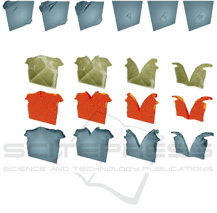
(a)
(b)
(c)
Figure 7: Tearing of a very deformable thin matter bloc. A tearing line is favoured by employing lower Sensor threshold in
the centre of the physical model. (a) Direct representation of the physical model, by using a sphere on each mass. (b)
Representation of the topological model, in which sewed and unsewed faces are rendered with distinct colours, allowing to
pursue the evolving topological modifications. (c) Rendering of the finally obtained geometrical model.
constant throughout simulation, thanks to the use of
the GMaps formalism: the number of darts is never
changed, even when topology is modified.
4 CONCLUSIONS
This paper proposed new contributions to the today’s
stream of research that envisages employing explicit
representations of the topological aspects to root the
coating processes over geometry free physics-based
methods. The general pipeline is made of cascading
models: physical → topological → geometrical.
On the physical side, we extended the Splitting-
MAT methodology, which enables the split to occur
onto the material elements, to 3D volume models.
We then introduced downstream a topologico-
geometrical pipeline adapted to this property of the
upstream physical model. As compared to previous
works on the 3-stages pipeline, which did not employ
Splitting MAT, the split-on-the-masses property
allows building rather simply a base topological
model, and further enables a cunning handling of the
topological transformations of this base structure
during simulation, under control of the Physics.
The obtained results exhibit precision in both the
dynamics and the visual (geometrical) aspects.
Hence, the Splitting MAT-powered 3-stages pipeline,
while being manageable, does not limit the richness
of the desired dynamics (dynamics of the fracture and
splits, propagation, etc.). Finally, a theoretical and
practical measure of the complexity of the
topologico-geometrical part shows that the pipeline
competes with integrated approaches and qualifies for
real time implementations.
In the future, we plan to creatively experiment
with more diverse constructs. Indeed, handling
physics (dynamics) / topology (spatial relations) /
A Topological-Geometrical Pipeline for 3D Cracking-like Phenomena
213

geometry (final image) in 3 clearly separated
cascading models introduces manageability in the
modelling processes, and variability in the
observation of the physically generated dynamics.
Hence, besides employing the base topology and
simple geometry, as presented in this article, the three
models may indeed drastically differ in their
structure, and in their complexity. We plan to build
over this advantage to experiment with varied
physical models upstream, and varied topological
constructs and geometrical renderings for each of
them: non-regular physical models, refined
topologies, diverse geometrical embedding, etc.
Rooting on formal approaches on both the physical
and topological sides will ease such future
explorations, we assume.
AKNOWLEDGMENTS
We thank to Saman Kalantari for the core 3D volumic
algorithms of the Splitting MAT system. Thanks to
Dr Lilian Aveneau for his help for rendering
animation. ACROE and ICA are supported by the
French Ministry of Culture.
REFERENCES
Carter, B.J., Wawrzynek, P.A. and Ingraffea, A.R., 2000.
"Automated 3-d crack growth simulation".
International Journal for Numerical Methods in
Engineering, vol 47, p. 229–253.
Chen, F., Wang, C., Xie, B. and Qin, H., 2013. "Flexible
and rapid animation of brittle fracture using the
smoothed particle hydrodynamics formulation".
Journal of Visualization and Computer Animation, vol
24, num. 3-4, p. 215-224.
Darles, E. Kalantari, S. Skapin, X. Crespin and B. Luciani,
A., 2011. "Hybrid Physical - Topological Modeling of
Physical Shapes Transformations". DMDCM 2011 -
Workshop on Digital Media and Digital Content
Managemen 2011t, China, p.154-157.
Fléchon, E., Zara, F., Damiand, G. and Jaillet, F., 2013. "A
generic topological framework for physical
simulation". 21
st
International Conference on
Computer Graphics, Visualization and Computer
Vision, Plzen, Czech Republic, p. 104-113. ISBN: 1-3.
Frerichs, D. Vidler, 1. and Gatzidis, C., 2015. "A survey on
object deformation and decomposition in computer
graphics". Computers & Graphics, vol 52, p 18-32.
Jund, T., Allaoui A., Darles E., Skapin X, Meseure, P. and
Luciani, A., 2012. "Mapping Volumetric Meshes to
Point-Based Motion Models". VRIPHYS 2012 - 9th
Workshop on Virtual Reality Interactions and Physical
Simulations, Darmstadt, Germany, p.11-20.
Kalantari, S., Luciani, A. and Castagné, N., 2014. "A New
Way to Model Physics-Based Topology
Transformations: Splitting Mat". 12th International
Symposium on Smart Graphics, Tapeï, Taiwan.
Springer, p.133-145.
Lienhart, P., 1994. "N-Dimensional Generalized
Combinatorial Maps and Cellula Quasi-Manifolds".
International Journal of Computational Geometry
Applications. vol 04, num. 03, p. 275-324.
Luciani, A. and Godard, A., 1997. "Simulation of Physical
Object Construction Featuring Irreversible State
Changes". Proceedings of WSCG. p 321-330.
Luciani, A., Allaoui, A., Castagné, N., Darles, E., Skapin,
X. and Meseure, P., 2014. "MORPHO-Map: A new
way to model animation of topological
transformations". Computer Graphics Theory and
Applications (GRAPP), Lisbonne, France, p. 1-13.
Manteaux, P.L., Sun, W.L., Faure, F., Cani, M.P. and
O'Brien, J.F., 2015. "Interactive Detailed Cutting of
Thin Sheets". In Proceedings of ACM SIGGRAPH
Motion in Games, p. 1–8.
Meseure, P., Darles, E. and Skapin, X., 2010. "Topology-
based Physical Simulation". Virtual Reality Interaction
and Physical Simulation, Copenhague, Denmark. p.1-
10.
Muguercia, L., Bosch, C. and Patow, G., 2014. "Fracture
modeling in computer graphics". Computers &
Graphics, Volume 45, p. 86-100.
Paulus, C., Untereiner, L., Courtecuisse, H., Cotin, S. and
Cazier, D., 2015. "Virtual Cutting of Deformable
Objects based on Efficient Topological Operations".
Visual Computer., vol 31, num. 6-8, p. 831-841.
Pauly, M., Keiser, R., Adams, B., Durth, P., Gross, M. and
Guibas, L.J., 2005. "Meshless Animation of Fracturing
Solids". ACM Trans. Graph., vol 24, num. 3, p. 957–
964.
Steinemann, D., Otaduy, M.A. and Gross, M., 2009.
"Splitting Meshless Deforming Objects with Explicit
Surface Tracking". Graph. Models. 2009, vol 71, num.
6, p. 209–220.
Zhuang, X., Augarde, C.E. and Mathisen, K.M. 2012.
"Fracture modeling using meshless methods and level
sets in 3D: Framework and modeling". International
Journal for Numerical Methods in Engineering., vol.
92, num. 11, p. 969–998
GRAPP 2018 - International Conference on Computer Graphics Theory and Applications
214
