
Research Progress of Multi-aperture Laser Transceiving Control for
Beam Combining Applications in IOE, CAS
Feng Li
1,2
, Xinyang Li
1,2,*
, Chao Geng
1,2
, Guan Huang
1,2,3
and Yan Yang
1,2,3
1
Institute of Optics and Electronics, Chinese Academy of Sciences, Chengdu, Sichuan 610209, China
2
Key Laboratory on Adaptive Optics, Chinese Academy of Sciences, Chengdu, Sichuan 610209, China
3
University of Chinese Academy of Sciences, Beijing 100049, China
Keywords: Multi-aperture Laser Transceiving, Beam Combining, Adaptive Fiber Coupling.
Abstract: Nowadays, the development of fiber laser beam combining faces new challenges during propagating
through the real long-range atmosphere. Aberrations in such transmission systems include turbulence-
induced dynamic aberrations located at the path from the fiber laser array to the target, besides the inherent
phase errors like phase noises and tip/tilt errors. Existing techniques, e.g., target-in-the-loop and delayed
stochastic parallel gradient descent, are difficult to deal with the fast-changing turbulence-induced tip/tilt
aberrations. But correcting these aberrations is critical for obtaining combined laser beams on the target
with the best beam quality. In this paper, research progress of multi-aperture laser transceiving control for
beam combining applications in IOE, CAS is presented. These novel techniques presented here provide
efficient ways to achieve tip/tilt control for the beam coupling from space to fiber and the outgoing laser
beams in the beam combining applications.
1 INTRODUCTION
Fiber laser techniques have been under intensive
investigations for their excellent beam quality, high
efficiency and flexible structure. While, single fiber
laser beam with high power and good beam quality
simultaneously is hard to achieve, owing to physical
limits like nonlinear effect, thermally-induced modal
instability, and thermal damage (Yu et al., 2011).
Coherent beam combining (CBC) gives excellent
solutions to these hard issues and shows great
prospects in laser systems like directed energy, free
space laser communications, and laser radar. Tiled
beam array and filled-aperture are the two main
architectures of fiber laser CBC. Compared with the
later one, tiled beam array method not merely
provides a flexible method producing high power
output with excellent beam quality, but also could
act as a scalable fiber laser transceiver. Recently
developed coherent tiled fiber laser arrays composed
of numerous fiber collimators have aroused a
significant interest (Weyrauch et al., 2011). In such
systems, traditional and monolithic large-aperture
transmitters are replaced by smaller sub-aperture
array for improved adaptive optics (AO)
performance. The phase distortions in these systems
are divided into piston and/or tip/tilt errors within
the sub-apertures (Filimonov et al., 2014). Benefited
from the mature fiber-integrated phase devices,
issues about piston errors have been widely
researched and well solved. Meanwhile, novel
device named adaptive fiber-optics collimator
(AFOC) has been invented to manipulate the tip/tilt
phases in fiber laser CBC systems (Liu et al., 2007
and Geng et al., 2013). Compared to conventional
tip/tilt devices like FSM, the AFOC drives fiber tip
directly to execute tip/tilt. Such devices are with
advantages of precise control, small inertia, high
resonance frequency and convenience for
assembling and integration (Lachinova et al., 2008).
Further development of the tiled beam array (or
fiber laser array) aims at highly efficient propagation
through the atmosphere, not merely realization of
CBC indoor. Thus, correcting aberrations, especially
the turbulence-induced aberrations located at the
transmission path, is critical for obtaining the best
beam quality and the highest power intensity on the
target. Alleviating the sub-aperture averaged piston-
type aberrations of the laser source and turbulence,
which is named as phase locking, is the basic item
for CBC under atmosphere. Beyond the piston-type
aberrations, compensation of the higher order
Li, F., Li, X., Geng, C., Huang, G. and Yang, Y.
Research Progress of Multi-aperture Laser Transceiving Control for Beam Combining Applications in IOE, CAS.
DOI: 10.5220/0006546200430049
In Proceedings of the 6th International Conference on Photonics, Optics and Laser Technology (PHOTOPTICS 2018), pages 43-49
ISBN: 978-989-758-286-8
Copyright © 2018 by SCITEPRESS – Science and Technology Publications, Lda. All rights reserved
43

aberrations within the sub-apertures is needed if we
want to further improve the performance of CBC
under the atmosphere. In fact, tip/tilt-type errors take
up the most part (almost 87%) of the aberrations for
Kolmogorov turbulence in each sub-aperture.
Without the tip/tilt-type errors, CBC under
atmosphere would be more efficient where higher
target hit-spot brightness could be obtained with
even less transmitted power (Vorontsov et al., 2016).
But such goal is blocked by the available bandwidth
of the tip/tilt devices and the performance of existing
control algorithm. The appearance of AFOC has
solved the bandwidth issues to a certain extent. In
this case, the performance of the control algorithm
becomes particularly important.
Different from the traditional AO control, where
extra wavefront sensors (like Hartmann-Shack
sensor) are needed to measure the monolithic
wavefront actively, fiber laser arrays mostly depend
on optimization algorithm for CBC owing to their
discrete architecture. Phasing through target-in-the-
loop (TIL) with hill-climbing type techniques (like
stochastic parallel gradient descent, SPGD) is the
main existing approach for current CBC under
turbulence (Weyrauch et al., 2016). In these schemes,
the power-in-the-bucket (PIB) metric, which
represents the laser power backscattered by the size-
limited target point and collected by a local
telescope, is utilized for power-maximization. The
tip/tilt control and the phase locking control are
mixed together in such single metric optimization
techniques. The hardest problem is that the available
bandwidth of AFOC (no more than 5 kHz) is much
less than that of the fiber-integrated phasing devices
(up to GHz), while the channel number of the former
is double of the latter one (Geng et al., 2011).
Obviously, existing methods are not fit for fiber
laser array CBC systems with fast-changing tip/tilt
errors.
New techniques making the best use of the
limited AFOC bandwidth are in urgent need. Recent
progress on techniques of adaptive fiber coupling
reported by IOE, CAS gives out new ideas on such
issues (Luo et al., 2014). In these methods, the fiber
coupling efficiency of the modified AFOC could be
improved with active tip/tilt-type phase errors
control. Tip/tilt control for both the coupling from
space to fiber and the outgoing laser beam is
obtained. Such techniques achieve parallel tip/tilt
control for each sub-aperture of the array, which is
independent from the phase control in the CBC
systems. In this paper, the research progress of
multi-aperture laser transceiving control for beam
combining applications in IOE, CAS is presented.
2 ADAPTIVE FIBER COUPLING
Here, we present the recent work of extending the
control bandwidth of the AFOC for adaptive fiber
coupling. An improved SPGD algorithm named
precise-delayed SPGD (PD-SPGD) is proposed for
the AFOC-based adaptive coupling system.
Figure 1 shows the structural scheme of the
AFOC coupling system. A uniform plane wave laser
beam is focused and coupled into the single-mode-
fiber (SMF) tip in the AFOC, part of the coupled
optical energy is sent to a terminal receiver and the
other part is detected by a photodetector (PD). The
PD voltage is utilized as the performance metric of
the control algorithm. Two-channel control signals
from the controller are amplified by high-voltage
amplifiers (HVAs) and then drive the AFOC for
closed loop control.
AFOC
Fiber splitter
Coupling
lens
Fiber tip
positioner
Receiver
Laser with
plan wave
Optical path
Electrical path
Controller
Control
voltages
Performance
metrics
HVA
PD
Figure 1: Structural scheme of adaptive coupling system
based on AFOC.
Response delay between the input and the output
is one of the key issues in almost all practical control
systems. Parameter τ
resp
is defined here as the delay
between the change of the control voltage and the
response of the metric and τ
SPGD
as the period of a
SPGD iterative cycle. Through massive experiments,
we find that τ
resp
keeps constant when the frequency
is below 10 kHz. The average value is about 0.1 ms
for both the X-direction and Y-direction of the
AFOCs. Such inherent response delay will lead to
inaccurate gradient estimation through the fast
iterative process of SPGD algorithm where τ
SPGD
becomes less than τ
resp
. For example, when τ
SPGD
is
less than 0.2 ms, metric J
-
(n)
and J
+
(n)
of the SPGD
algorithm is almost totally determined by the drive
voltages of U
(n)
+ΔU
(n)
and U
(n-1)
-ΔU
(n-1)
respectively
(n represents the time point). This will lead to
opposite gradient estimation results if traditional
SPGD algorithm is utilized as:
( 1) ( ) ( ) ( ) ( )n n n n n
U U U J J
(1)
where γ is the gain coefficient.
So, readjustment of the correspondence between
the metric and the disturbed voltage is needed, and
PHOTOPTICS 2018 - 6th International Conference on Photonics, Optics and Laser Technology
44
one way that might work is to set a controllable time
delay. This idea originates from the delayed-SPGD
(D-SPGD) algorithm, which has been successfully
used to compensate the time delay caused by the
optical wave propagation in CBC experiments
(Weyrauch et al., 2016). Such improved algorithm is
named as Precise-Delayed SPGD algorithm (PD-
SPGD) here. The iterative procedure of the control
voltage during each iteration cycle (n) can be
described by the following rule:
( 1) ( ) ( ) ( ) ( )
/2
n n n n n n n n
i i N
U U U J J
(2)
where
0,1,...,i MN
. Here, the integer number Δn
= M-1 is the integral-delay parameter and i ≥ 0 is the
precise-delay parameter that accounts for the
response delay τ
resp
. N is the number of sampling
points of metrics within one time of iteration, which
determines the accuracy of the compensation that
can be achieved.
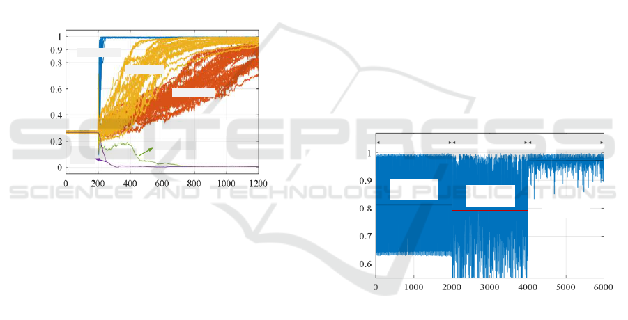
Normalized performance metrics
/ J
Iteration number / n
Δn=0, i=5
Δn=1,
i=15
Δn=1, i=12
Δn=1, i=8
Open
loop
Closed loop
Δn=1, i=10
Figure 2: Iteration curve of different delay parameter
settings in the experiment of static angular error
correction.
Figure 2 shows the experimental results of fiber
coupling with 367 μrad static angular error (almost
misalignment of 5.5 μm at the fiber end). The
iteration rate of the PD-SPGD algorithm is 8 kHz
and the sampling rate is 80 kHz, thus τ
SPGD
=0.125
ms, N=10. To compensate the response delay (96
μs), τ
comp
is set to 0.127 ms, the integral delay
parameter Δn=1 and the precise delay parameter
i=10 (the closest integer number to 0.127/0.125 and
10×0.127/0.125 correspondingly). As shown in
Figure 2, the iteration curve diverges when Δn=0
and i=5. When parameters Δn=1 and i=8, 10, 12 (the
corresponding actual compensation time is 0.1 ms,
0.125 ms and 0.15 ms), the algorithm starts to
converge and corresponding convergence time t
c
(equal to the time needed for the normalized metric
rise to 90%) is 55 ms, 2.5 ms and 137.5 ms through
statistics of 20 sets of data. Finally, when Δn=1 and
i=15 (equivalent to using the D-SPGD algorithm),
the iteration cure diverges again.
Sine angular jitter with frequency of 100 Hz and
amplitude of 166 μrad is loaded on the plane wave
and corresponding experimental results of SMF
adaptive coupling using SPGD and PD-SPGD are
shown in Figure 3. Iterative rates of these two
algorithms are 3 kHz and 8 kHz respectively.
Control parameters of both algorithms are carefully
tested and optimized. The metric is with an average
value of 0.81 and mean square error (MSE) of 0.13
under open loop. The average metric decreases to
0.79 and the MSE increases to 0.14 when SPGD
algorithm is utilized. The average metric increases to
0.97 and the MSE decreases to 0.019 when SPGD
algorithm executes. SPGD becomes invalid under
such circumstances, while PD-SPGD still works
fine.
Above results reveal that the PD-SPGD
algorithm proposed here has less convergence time
and could get better performance than conventional
SPGD algorithm. Meanwhile, this improved
algorithm competently deals with dynamic tip/tilt
errors with frequency approximating one hundred
Hz, which shows potential abilities when facing
turbulence-induced dynamic aberrations.
Normalized performance metrics
/ J
Iteration number / n
Mean=0.81
MSE=0.13
Open loop
SPGD
PD-SPGD
Mean=0.79
MSE=0.14
Mean=0.97
MSE=0.019
Figure 3: Comparison between the SPGD and PD-SPGD
algorithm when the frequency of sine angular jitter is 100
Hz.
3 CO-APERTURE
TRANSCEIVING OF TWO
COMBINED BEAMS
The amount of the coupled power that enters to the
SMF in the AFOC is inversely proportional to the
displacement of the fiber-tip center in respect to the
focal-spot centroid position of the incident beam.
The pitch between the delivery fiber tip and the focal
spot center is caused by the wavefront tip/tilt
Research Progress of Multi-aperture Laser Transceiving Control for Beam Combining Applications in IOE, CAS
45
aberrations. According to the principle of optical
reciprocity, when the received optical wave power is
maximized through the AFOC control, the tip/tilt
errors are equivalently corrected for the counter-
propagating outgoing and received laser beams in
the delivery fiber. These two laser beams could
share the same optical fiber path with help of
directional fiber circulators or free-space fiber
isolators. Meanwhile, for CBC with multi-AFOCs,
such tip/tilts control could work in parallel for each
single aperture. That means the tip/tilts control keeps
two dimensional regardless of the scale of the CBC
array.
Here, the current work about the co-aperture
fiber laser transceiving propagation using AFOCs
for both coupling and collimating in IOE, CAS are
presented (Li et al., 2015). Fiber laser array
composed of two-element AFOCs is built up and
indoor simulated turbulence is set to introduce
aberrations. SPGD algorithm is employed here to
promote the fiber coupling efficiency and the
combining efficiency of the fiber-array outgoing
beams.
Micro-
ojective
Far-field fiber laser
source @ 1064nm
Monitor
Local fiber laser
source@1064nm
PDPD
Fiber
splitter
AFOCs
TL
Beam
splitter
Optical
circulators
Fiber
Electrical
CMOS
10x
HVA
Data acquisition &
control platform
AFOCs’
arrangement
Heater
Simulated
turbulence
Phase
modulators
32mm
Φ28mm
Figure 4: Experimental setup. PD: photo-detector. HVA:
high voltage amplifier. TL: transform lens.
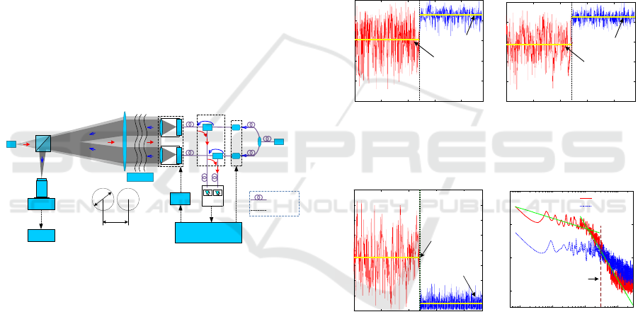
Experimental setup of the co-aperture laser beam
transceiving propagation is illustrated in Figure 4. A
transform lens (TL) is employed to simulate the
optical far-field. A fiber laser with the fiber tip
located at the far-field is set to be as the unresolved
target and the target source. The target outgoing
beam is collimated by the TL, and heated to generate
the atmospheric turbulence aberrations. Then, the
phase-distorted collimating beam is focused and
coupled into the internal polarization-maintaining
fibers (PMFs) of the AFOC array separately. The
coupled beams are detected by PDs. At the same
time, the local collimated fiber laser beams from the
two AFOCs are also heated to generate conjugated
aberrations. The two phase-distorted sub-beams are
focused by the TL, and then detected by a high
speed CMOS camera for observation.
The iteration rate of the SPGD algorithm is about
1.15 kHz. Figure 5 (a) and Figure 5 (b) show the
evolution curves of coupling power of the AFOCs,
denoted as P
1
and P
2
, when tip/tilt control is off and
on under the influences of simulated turbulence.
Here, P
1
and P
2
are normalized by the maximum
value in respective closed loop. Duration of both the
open and closed states is all about 12-second. The
average value of P
1
for one AFOC increases from
0.61 in open loop to 0.85 in closed loop, and the
MSE drops from 0.16 to 0.048. For P
2
, the average
value increases from 0.57 to 0.85 and the MSE drops
from 0.14 to 0.04 correspondingly. The results
indicate that the efficiency of coupling laser beam
with distorted wave-front from space into PMF can
be effectively promoted through tip/tilt error control
with AFOCs.
Normalized P
1
0 5 10 15 20
0
0.2
0.4
0.6
0.8
1
Time (s)
(a)
Average=0.61
Average=0.85
Open loop
Closed loop
0 5 10 15 20
0
0.2
0.4
0.6
0.8
1
Normalized P
2
Time (s)
(b)
Average=0.57
Average=0.85
Open loop
Closed loop
Figure 5: Evolution curves of the coupled laser power
normalized by the maximum value in separately closed
loop. (a) Received by AFOC-1. (b) Received by AFOC-2.
0 5 10 15 20
0
5
10
15
20
25
30
35
40
Time (s)
Absolute value of centroid's deviation (
rad)
Open loop Closed loop
(a)
Average=17.5 μrad
Average=2.35 μrad
Time (s)
35
30
25
20
15
10
5
0
Absolute value of centroid’s deviation (μrad)
0 5 10 15 20
40
10
-1
10
0
10
1
10
2
10
-16
10
-14
10
-12
10
-10
Frequency (Hz)
Power spectrum of centroid's deviation (rad
2
/Hz)
Open loop
Closed loop
(b)
Open loop
Closed loop
30 Hz
Frequency (Hz)
Power spectrum of centroid’s deviation (rad
2
/Hz)
-10
10
-12
10
-14
10
-16
10
-1
10
0
10
1
10
2
10
- 2/3
- 10/3
Figure 6: Combination of the two AFOC-collimating
beams in the far-field. (a) The absolute-value evolution
curve of the diffraction pattern centroid’s deviations. (b)
Frequency spectrum-density distribution of the curve in
(a).
Figure 6 (a) depicts the absolute-value evolution
curve of the diffraction pattern centroid’s deviations
of the two AFOC-collimating beams in the far-field.
The average absolute-value of the centroid’s
deviation drops from 17.5 μrad in open loop to 2.35
μrad in closed loop, the MSE value drops from 6.59
μrad to 1.35 μrad, and the peak-valley value drops
from 36.8 μrad to 8.54 μrad (the diffraction-limited
angle of a single AFOC aperture is about 92 μrad).
Figure 6 (b) describes the frequency spectrum-
PHOTOPTICS 2018 - 6th International Conference on Photonics, Optics and Laser Technology
46
density distributions of the open and closed loop
curves in Figure 6 (a), respectively. Deviations of
less than 30 Hz have been well corrected. The
results show that the tip/tilt errors of the outgoing
laser beams are equivalently corrected when the
received optical wave power is maximized.
4 CBC BASED ON 7-APERTURE
LASER TRANSCEIVING
Experiment in part 3 is focused on the tip/tilt
aberrations correction and the piston aberrations are
not considered in. However, phase-locking is the
basic condition for CBC. To obtain CBC of the
AFOC array, tip/tilt control with adaptive fiber
coupling is cooperated with the TIL-based phasing
techniques. Here we present the researches about
CBC based on multi-aperture laser transceiving in
IOE, CAS (Li et al., 2017).
PD with a
pinhole
PBS
AFOC×7
Transform lens
1×8
Fiber Splitter
Fiber laser source
11mW@1064nm
Fiber
circulator×7
PD×7
Hot water
Fiber laser source
2W@1064nm
Phase-locking
controller
Laser beam
coupling controller
High voltage
amplifier
Fiber tip
Beam
splitter
Mirror
10x
Micfro-
objective
CMOS
camera
Monitor
AFOC array
PZT-PC×7
PZT-PC×7
Figure 7: Experimental setup of CBC based on 7-aperture
laser transceiving. PZT-PC: piezoelectric-ceramic-ring
fiber-optic phase compensator. AFOC: adaptive fiber-
optics collimator. PD: photo detector. PBS: polarized
beam splitter.
Fiber laser CBC experiment setup with AFOC
array of seven sub-apertures is illustrated in Figure 7.
Polarized and single-frequency fiber laser beams
from the 7-subaperture AFOC array are heated by
hot water to bring in simulated dynamic turbulence
aberrations and focused by a transform lens. Then
the focused beamlets are detected by a PD with a
pinhole for phase-locking control (PL) and a high-
speed CMOS camera for observation simultaneously.
Piezoelectric-ceramic-ring fiber-optic phase
compensators (PZT PC) are utilized here to correct
the piston-type errors of the array. A pigtail fiber
with its end located in the focal spot of the transform
lens is used as a simulated objective in the far-filed.
The monolithic-beam from the fiber tip is collimated
by the transform lens and cut off by the array, and
then focused and coupled into the PMFs of each
AFOC respectively. Metrics detected by each PD are
utilized for tip/tilt control (TT) for each AFOC in
parallel.
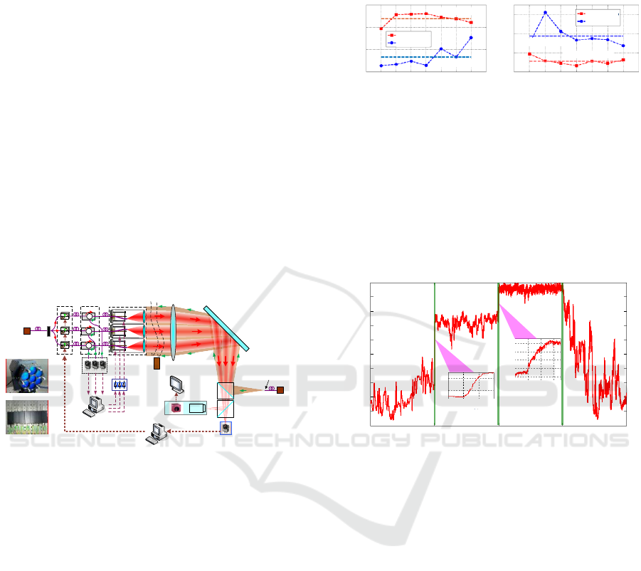
Average=0.94
Average=0.76
Average=0.18
Average=0.055
Normalized coupled
power
Mean square error of
the coupled power
Closed loop
Open loop
Closed loop
Open loop
1
0.9
0.8
0.7
AFOC number
1 2 3 4 5 6 7
1 2 3 4 5 6 7
AFOC number
0.3
0.2
0.1
0
(a) (b)
Figure 8: Average (a) and mean square error (b) of the
normalized coupled power for each AFOC when TT
control is in open loop and closed loop.
The average normalized coupled power for all
the seven AFOCs is about 0.76 without TT control
and then increases to 0.94 when TT control is
brought in as shown in Figure 8 (a). The average
MSE of the coupled power for all the seven AFOCs
is about 0.18 in open loop and then turns to 0.055 in
closed loop as illustrated in Figure 8 (b).
Average=0.21
MSE=0.096
Average=0.72
MSE=0.042
Average=0.96
MSE=0.016
Average=0.40
MSE=0.023
No control
PL
PL and TT
TT
0.95
0.9
0.85
0.8
0.75
10 10.02 10.04
9.98
4.995
5
5.005
5.01
0.6
0.4
1
0.9
0.8
0.7
0.6
0.5
0.4
0.3
0.2
0.1
0
Time (s)
0 5 10 15 20
Normalized PIB metric
Figure 9: The normalized PIB metrics acquired by PD as
the function of time.
Figure 9 shows the normalized PIB metric
acquired from the PD as the function of time during
four stages, which are no control stage, PL stage, PL
and TT stage, and single TT stage. The PIB metric is
normalized via being divided by the maximum PIB
during each stage. Without any control, the mean
PIB metric is just 0.21 and the corresponding MSE is
0.096 due to the simulated turbulence and the phase
noise of the transmission fibers. When only PL
control turns on, the PIB metric is locked at a higher
value with an average of 0.72, which is 3.4 times of
that for no control stage. Meanwhile, the MSE
decreases to 0.042. Then the TT control is brought in
and the PIB metric is further optimized. The metric
is with an average of 0.96 and MSE of 0.016, which
is only 1/6 of that in the no control stage. The
convergence of the adaption process after the TT
control is switched on takes time about 30 ms, which
equals to the time that each AFOC needs to
maximize the coupled power. Such results indicate
Research Progress of Multi-aperture Laser Transceiving Control for Beam Combining Applications in IOE, CAS
47
that we realizes the parallel tip/tilt control for each
AFOC and such control is independent from the
phase locking, which is quite different from the
existing techniques.
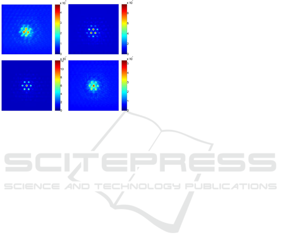
(a) (b)
(c) (d)
Cumulative gray
-scale value
Cumulative gray
-scale value
Cumulative gray
-scale value
Cumulative gray
-scale value
No control PL
PL and TT TT
Figure 10: The long-exposure far-field intensity
distributions. (a) No control. (b) PL control. (c) PL and TT
control. (d) TT control.
The long-exposure far-field intensity
distributions during the four control stages are
shown in Figures 10(a-d), respectively. The long-
exposure pattern is diffused by the simulated
turbulence and the fringe visibility is very weak
when no control is implemented. Fringe contrast
increases when PL works. Due to the simulated
turbulence and the initial static pointing errors of the
AFOCs during assembling, intensity of the side
lobes located bellow the main lobe approximates
that of the main lobe when only PL control works.
Further pre-compensation of the tip/tilt-type errors
through the TT control could resolve such issues and
results in pattern (Figure 10 (c)) comparable with the
ideal pattern. Sole TT control just benefits the
intensity of the central point, but not the fringe
contrast (Figure 10 (d)). All the results above
indicate that excellent fiber laser array CBC under
simulated turbulence has been achieved through the
cooperation of the tip/tilts correction based on multi-
aperture laser transceiving control and the active
phase locking control.
5 CONCLUSIONS
Future CBC of the tiled fiber laser array aims at
efficient transmission under atmosphere, which will
inevitably face challenges of alleviating the
turbulence-induced dynamic aberrations distributed
in the whole array aperture. Existing research results
mainly based on TIL and optimization algorithms
suffer from the defects of poor bandwidth utilization
efficiency, especially for the bandwidth-limited
tip/tilt devices represented by AFOCs. To solve
these issues, techniques of multi-aperture laser
transceiving control have been developed by IOE,
CAS. Such methods give abilities of efficient and
parallel adaptive correction to the tiled fiber laser
array. Research progresses on improved SPGD
algorithm of fiber coupling, co-aperture transceiving
of fiber laser array with adaptive tip/tilts corrections,
and CBC of tiled fiber laser array are presented.
Excellent results indicate the potential applications
of such techniques in fiber coupling, laser
communication and beam projection applications.
This work is supported by the National Natural
Science Foundation of China under grant No.
61675205, and the CAS “Light of West China”
program.
REFERENCES
Yu, C. X., Augst, S. J., Redmond, S. M., 2011. Coherent
combining of a 4kW, eight-element fiber amplifier
array. Opt. Lett. 36/14, 2686-2688.
Weyrauch, T., Vorontsov, M. A., Carhart, G. W.,
Beresnev, L. A., Rostov, A. P., Polnau, E. E., Liu, J. J.,
2011. Experimental demonstration of coherent beam
combining over a 7 km propagation path. Opt. Lett.
36/22, 4455-4457.
Filimonov, G. A., Vorontsov, M. A., Lachinova, S. L.,
2014. Performance analysis of a coherent tiled fiber-
array beam director with near-field phase locking and
programmable control of tip/tilt and piston phases.
Proc. SPIE 8971/9, 1-6.
Liu, L., Vorontsov, M. A., Polnau, E., Weyrauch, T.,
Beresnev, L. A., 2007. Adaptive phase-locked fiber
array with wavefront phase tip-tilt compensation using
piezoelectric fiber positioners. Proc. SPIE 6708/0K, 1-
12.
Geng, C., Luo, W., Tan, Y., Liu, H., Mu, J., Li, X., 2013.
Experimental demonstration of using divergence cost-
function in SPGD algorithm for coherent beam
combining with tip-tilt control. Opt. Express 21/21,
25045–25055.
Geng, C., Zhao, B., Zhang, E., Luo, W., Tan, Y., Zhu, Y.,
Yang, H., Mu, J., Li, X., Duan, K., Zhao, W., 2013.
1.5 kW Incoherent beam combining of four fiber
lasers using adaptive fiber-Optics collimators. IEEE
Photon. Technol. Lett. 25/13, 1286-1289.
Lachinova, S. L., Vorontsov, M. A., 2008. Laser beam
projection with adaptive array of fiber collimators. II.
Analysis of atmospheric compensation efficiency. J.
Opt. Soc. Amer. A 25/8, 1960–1973.
PHOTOPTICS 2018 - 6th International Conference on Photonics, Optics and Laser Technology
48

Vorontsov, M. A., Filimonov, G., Ovchinnikov, V.,
Polnau, E., Lachinova, S. L., Weyrauch, T., Mangano,
J., 2016. Comparative efficiency analysis of fiber-
array and conventional beam director systems in
volume turbulence. Appl. Opt. 55/15, 4170–4185.
Weyrauch, T., Vorontsov, M. A., Mangano, J.,
Ovchinnikov, V., Bricker, D., Polnau, E. E., Rostov, A.
P., 2016. Deep turbulence effects mitigation with
coherent combining of 21 laser beams over 7 km. Opt.
Lett. 41/4, 840-843.
Geng, C., Li, X., Zhang, X., Rao, C., 2011. Coherent beam
combination of an optical array using adaptive fiber
optics collimators. Opt. Commun. 284/24, 5531–5536.
Luo, W., Geng, C., Wu, Y., Tan, Y., Luo, Q., Liu, H., Li,
X., 2014. Experimental demonstration of single-mode
fiber coupling using adaptive fiber coupler. Chin. Phys.
B 23/1, 014207.
Li, F., Geng, C., Li, X., Qui, Q., 2015. Co-aperture
transceiving of two combined beams based on
adaptive fiber coupling control. IEEE Photon. Technol.
Lett. 27/17, 1787–1790.
Li, F., Geng, C., Huang, G., Yang, Y., Li, X., Qui, Q.,
2017. Experimental demonstration of coherent
combining with tip/tilt control based on adaptive
space-to-fiber laser beam coupling. IEEE Photon. J.
9/2, 7102812.
Research Progress of Multi-aperture Laser Transceiving Control for Beam Combining Applications in IOE, CAS
49
